Left Vertical Console
Fuel Management Panel
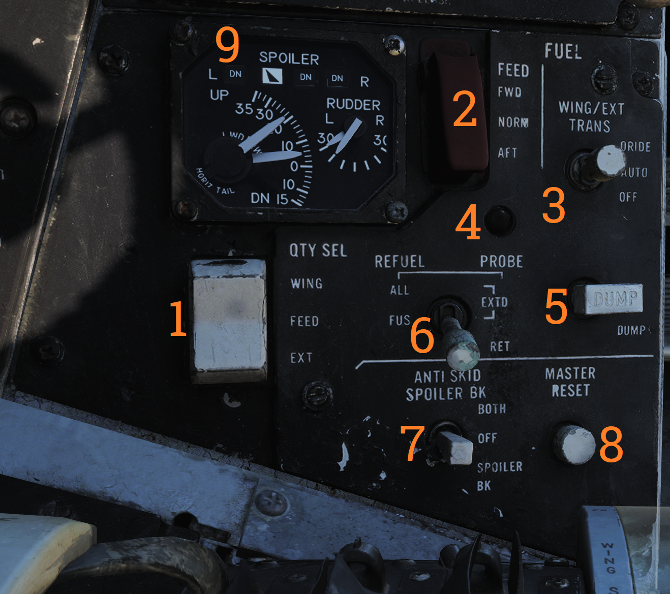
Control panel for various fuel-related systems, CADC master reset, and the anti-skid system.
| No. | Control/Indicator | Function |
|---|---|---|
| 1 | QTY SEL switch | Switch selecting what the fuel quantity tapes on the fuel quantity display shows. Spring-loaded to FEED. FEED - Shows respective feed and fuselage tank fuel quantity. WING - Shows respective wing tank fuel quantity. EXT - Shows respective external fuel tank quantity. |
| 2 | FEED switch | Switch selecting fuel feed to the engines. Guard locks the switch to NORM until lifted. |
| 3 | WING/EXT TRANS switch | Switch selecting operation of the wing and external tanks. ORIDE - Override. AUTO - Normal position. OFF - Turns off fuel feed from the wing and external tanks. |
| 4 | Refueling probe indicator light | Transition light illuminated when refueling probe is not in extended or retracted position. |
| 5 | DUMP switch | OFF/DUMP switch. Allows fuel dump when speed brakes are retracted, afterburner off and weight off wheels. |
| 6 | REFUEL PROBE switch | Selection switch toggling operation of refueling probe. ALL EXTD - All extended, extends refueling probe and allows refueling of all tanks. Also resets WING/EXT TRANS switch to AUTO. FUS EXTD - Fuselage extended, extends refueling probe and allows refueling of only fuselage tanks. RET - Retracted, retracts refueling probe. |
| 7 | ANTI SKID SPOILER BK switch | Selection switch determining operation anti-skid and spoiler brake systems. BOTH - Enables both anti-skid and spoiler brake function with weight on wheels. OFF - Turns off both systems. SPOILER BK - Spoiler brake, enables spoiler brake function with weight on wheels. |
| 8 | MASTER RESET button | Resets CADC failure detection system and associated fault displays. |
Control Surface Position Indicator
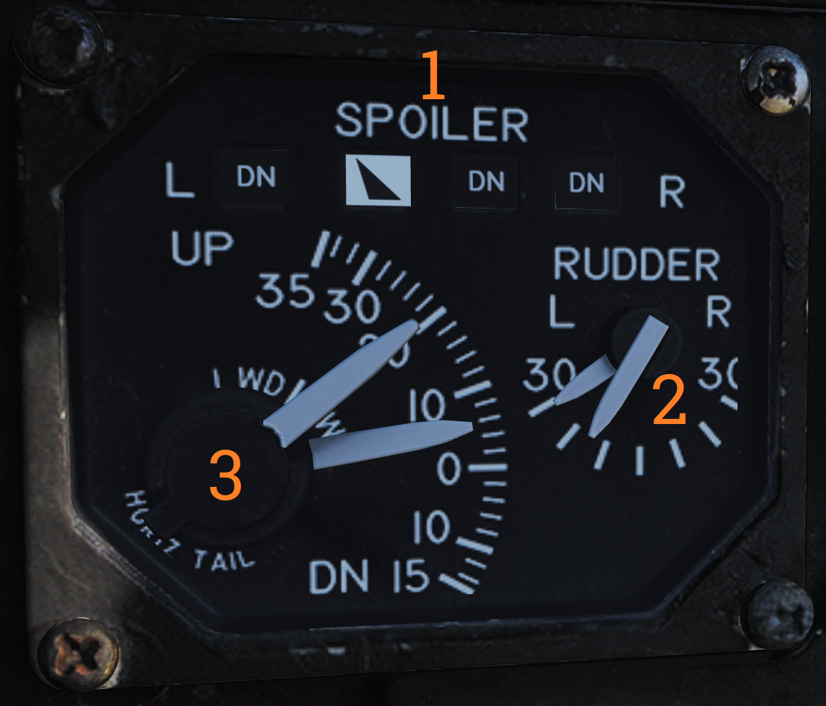
Indicator for indication of control surface positions.
| No. | Indicator | Function |
|---|---|---|
| 1 | SPOILER | Spoiler position indicators. DN - Down, flush with wings. Up-arrow - Extended above wing. Down-arrow - Drooped below wing surface. |
| 2 | RUDDER | Rudder position indicators, shows position of left and right rudders, each marked L or R. |
| 3 | HORIZ TAIL | Horizontal stabilizer position indicators, shows position of left and right stabilizer surfaces, marked L or R respectively. |
Launch Bar Abort Panel
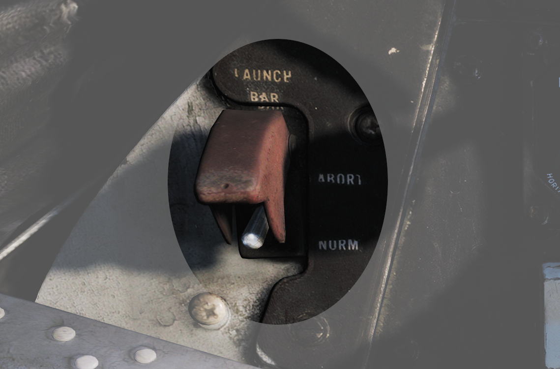
LAUNCH BAR – Selection switch – When held in ABORT lifts the launch bar for launch abortion. Spring-loaded to NORM (Normal) which is the standard position. Not currently used in DCS.
Landing Gear Control Panel
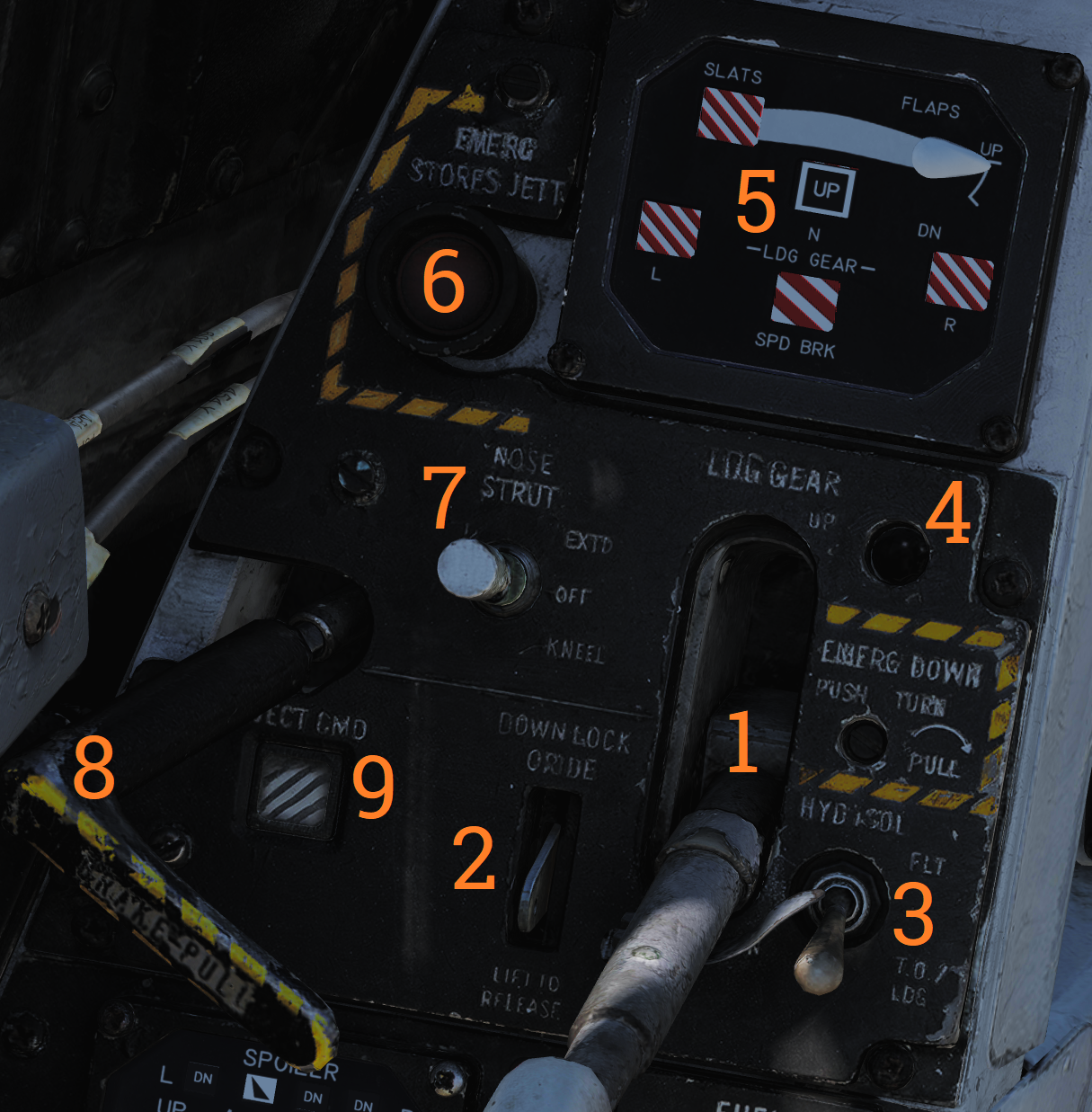
Control panel for the main landing gear and emergency stores jettison.
| No. | Control/Indicator | Function |
|---|---|---|
| 1 | LDG GEAR | Landing gear handle. Selects gear UP or DOWN. For emergency extension in DOWN position, push handle in, turn clockwise and pull out. This releases a compressed nitrogen charge for emergency extension. |
| 2 | DOWN LOCK ORIDE | Indicates weight on wheels when moved down by solenoid. Can be lifted up to override. Non-functional in DCS. |
| 3 | HYD ISOL | Switch isolating landing gear, nosewheel steering and wheel brakes from the combined hydraulic system. Automatically moved to T.O./LDG by LDG GEAR in DOWN position. FLT - In flight operation, isolates systems listed above. T.O./LDG - Take-off/landing, connects systems listed above, allowing them to operate. |
| 4 | Transition light | Illuminates to indicate landing gear position not corresponding to current LDG GEAR handle position. |
| 5 | EMERG STORES button | Emergency stores jettison. Illuminates to indicate activation when pressed. |
| 6 | NOSE STRUT switch | Switch selecting nosewheel strut retraction. EXTD - Extend, extends nosewheel strut and raises and locks launch bar. OFF - Turns off nosewheel strut movement, spring-loaded to this position. KNEEL - Releases pressure from nosewheel strut to retract it, kneeling aircraft. Also unlocks launch bar. |
| 7 | BRAKE-PULL handle | Parking brake, pull out to apply parking brake, push in to release. |
| 8 | EJECT CMD indicator | Indicates ejection system mode for the back seat. PILOT - Pilot ejects both crewmembers, RIO only himself. MCO - Each position ejects both crewmen. |
Wheels and Flaps Position Indicator
Indicates position of flaps and slats, speed brakes, and the landing gear. The slats are indicated as follows:
 | Power off or maneuver slats extended. |
|---|---|
 | Slats extended. |
 | Slats retracted. |
Flap Position is displayed by an indicator moving between UP and DOWN. The first marked section of the indicator indicates maneuver flap-range. The landing gear is indicated as follows:
| Power off or unsafe gear. |
|---|---|
 | Gear down. |
 | Gear retracted and doors closed. |
Speed brakes are indicated as follows:
| Speed brake system power off. |
|---|---|
 | Speed brake partial extension, not in motion. |
 | Speed brake fully extended. |
 | Speed brake retracted. |