Left Side Console
G-Valve Button
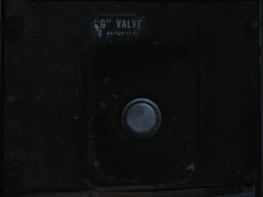 Pressed to test inflation of g-suit.
Oxygen-Vent Airflow Control Panel
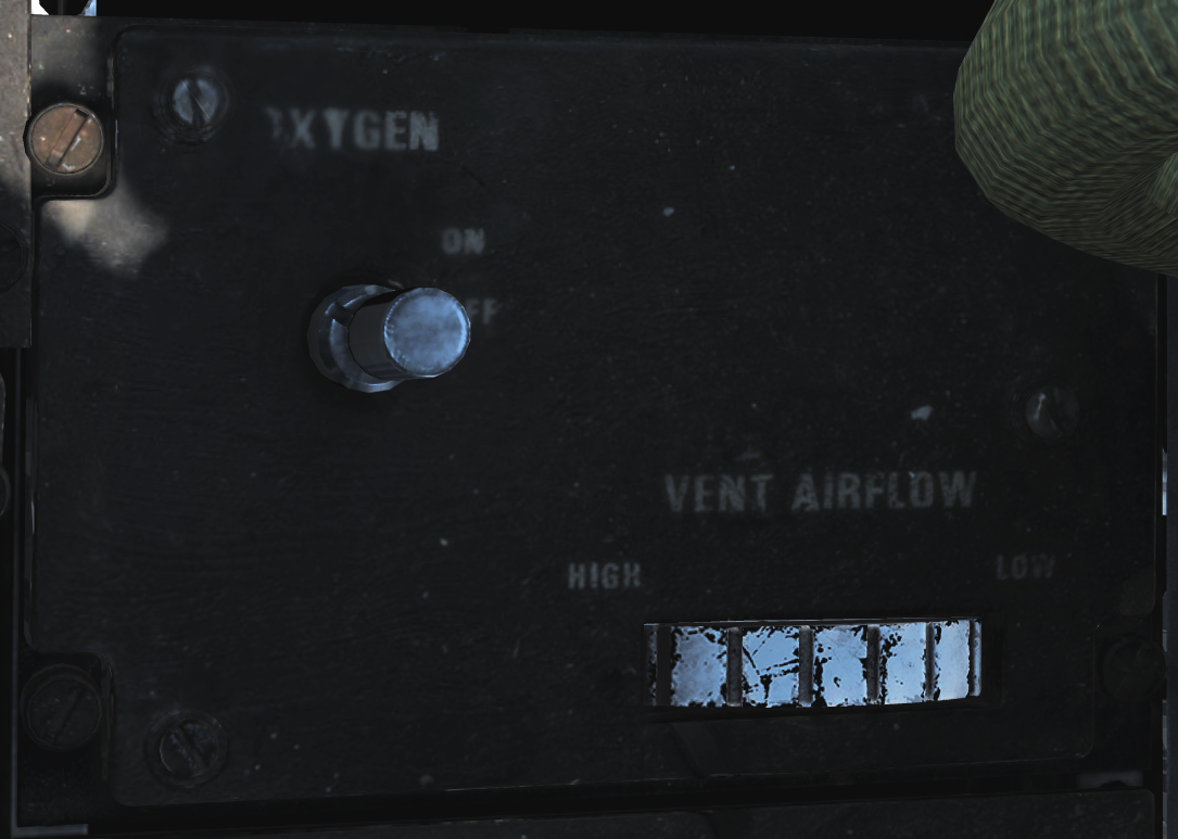 Controls ventilation airflow to pressure suit or seat cushions and oxygen to RIO mask.
| No. | Control | Function |
|---|---|---|
| 1 | VENT AIRFLOW dial | Used to control airflow through the pressure suit or seat cushions if no pressure suit is worn. |
| 2 | OXYGEN switch | Switch with ON/OFF positions. Controls oxygen flow to the mask. |
Data Stowage Compartment
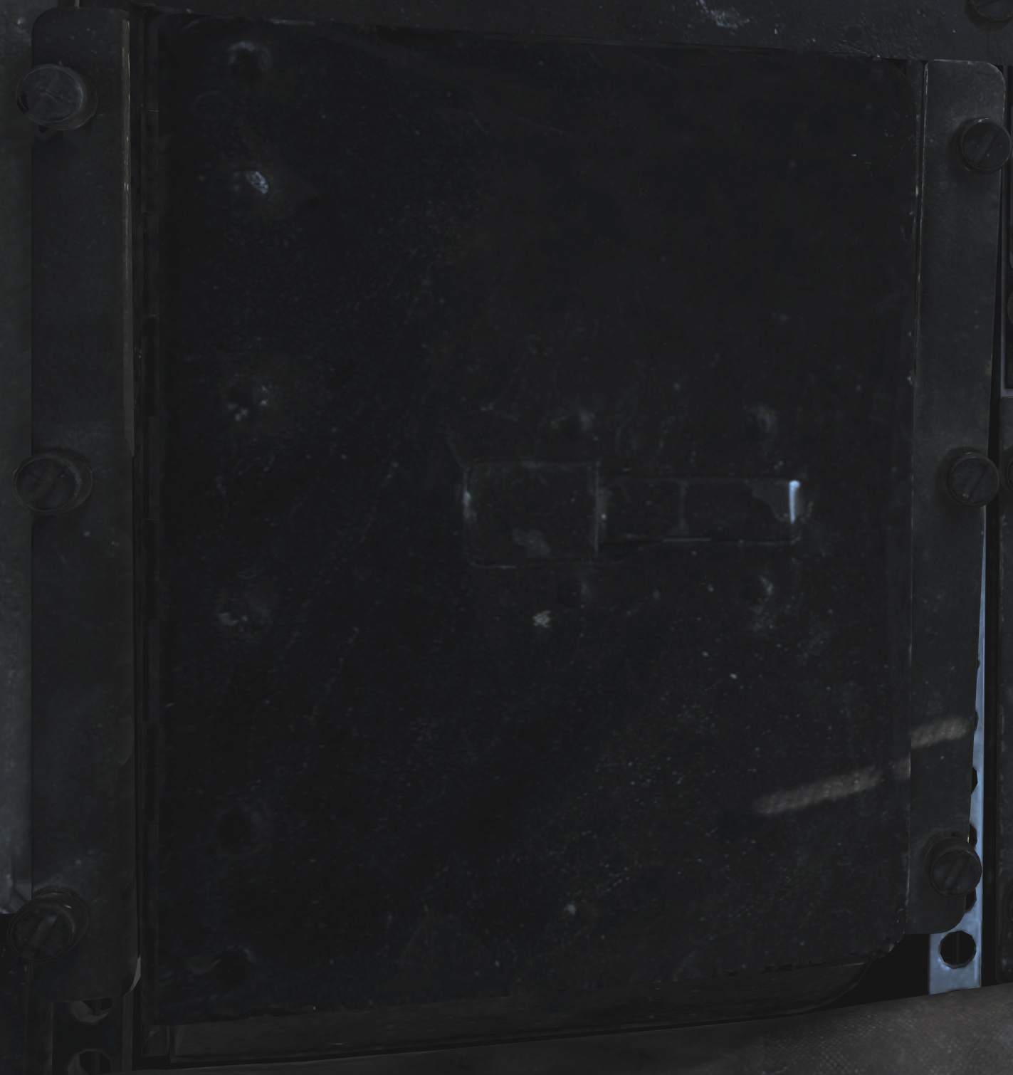 The data stowage panel is a small compartment for equipment storage and mission briefing materials etc.
TACAN Control Panel
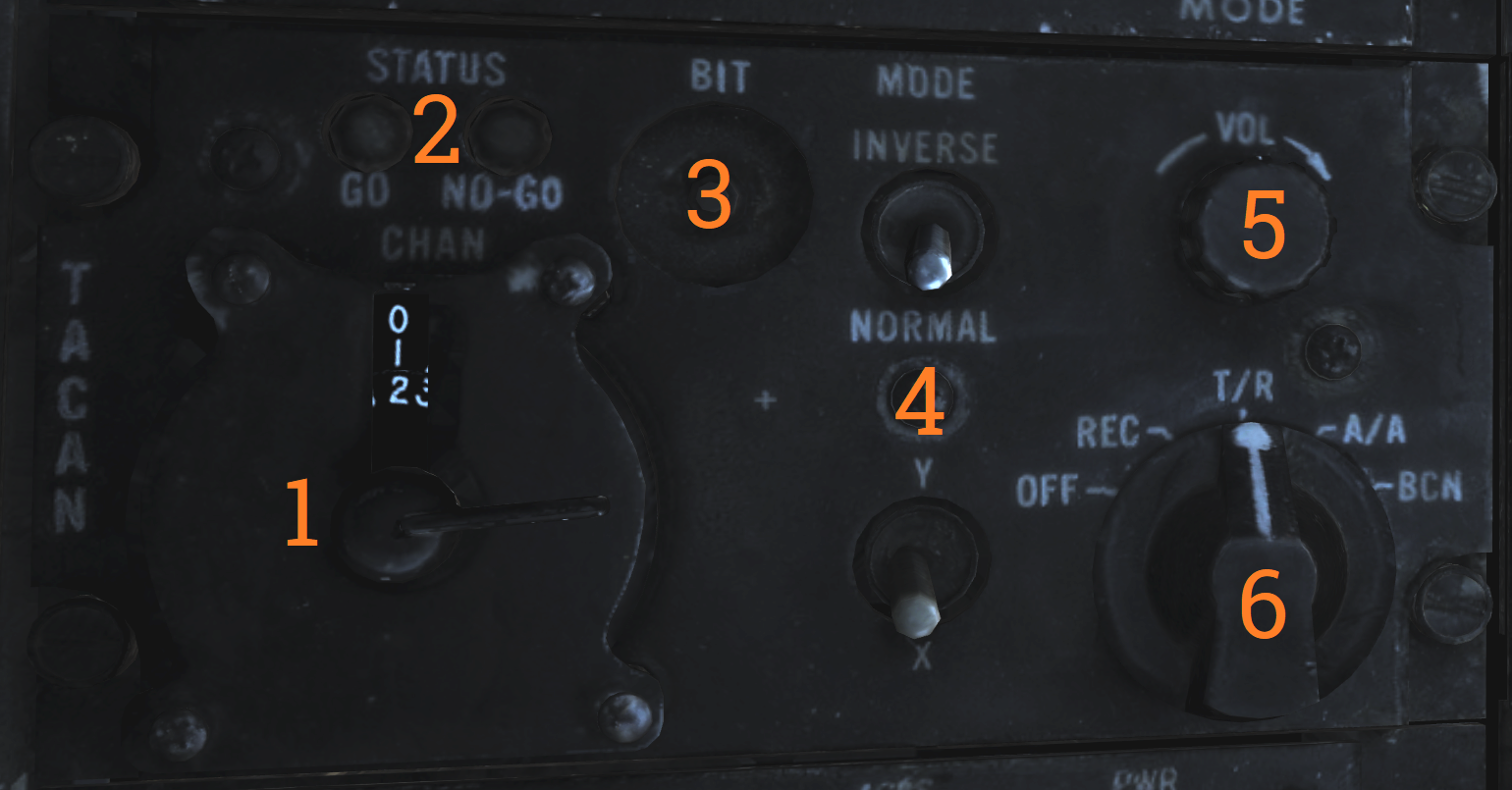 TACAN control panel letting the RIO control TACAN if in command of it.
| No. | Control/Indicator | Function |
|---|---|---|
| 1 | Dual rotary switch | Outer dial selects first two digits and inner dial selects last digit for TACAN channel selection. |
| 2 | GO & NO-GO lights | Lights indicating result of TACAN BIT. |
| 3 | BIT button | Button initiating TACAN BIT. |
| 4 | MODE switches | Switches mode for TACAN operation and selects X or Y channels. INVERSE mode not functional. |
| 5 | VOL knob | Volume control knob for TACAN audio to RIO. |
| 6 | Mode knob | Selects TACAN mode. OFF - TACAN is off. REC - Receive only. T/R - Transmit and receive, enables range readout. A/A - Air to air TACAN mode. BCN - Beacon TACAN mode. (Non-functional) |
Communication/TACAN Command Panel
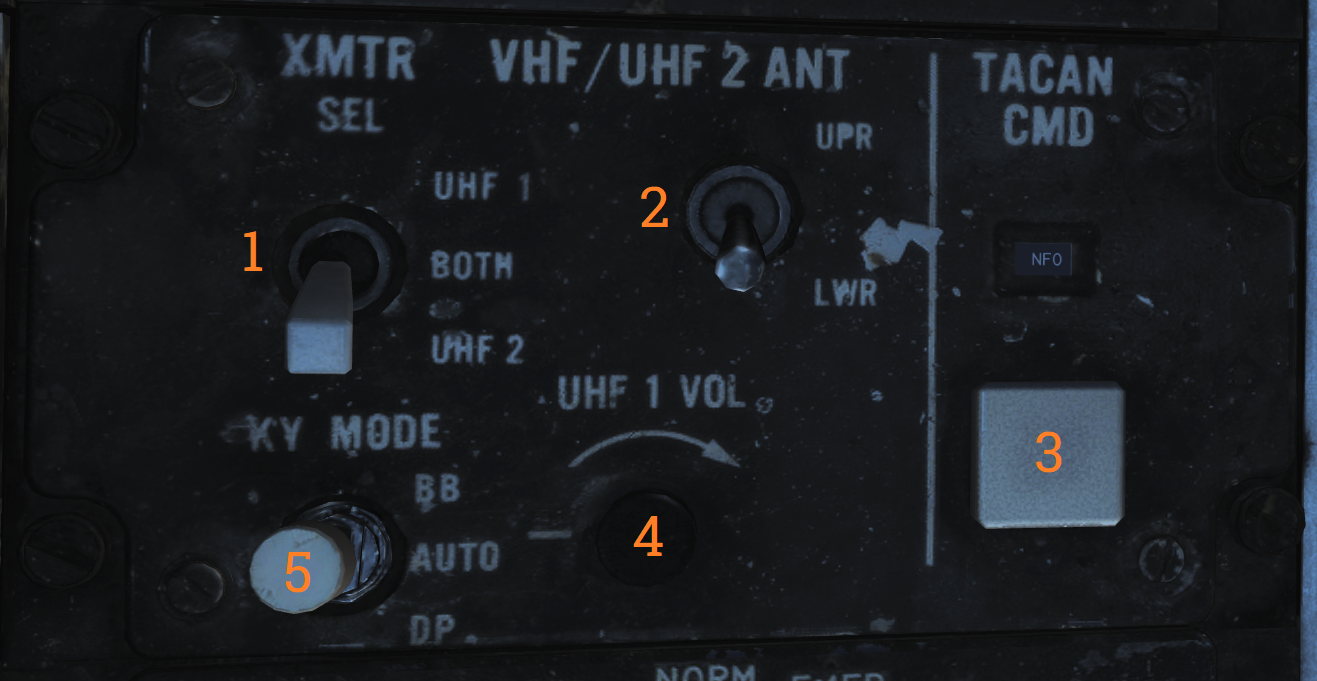 Panel controlling ICS radio settings and crewmember in control of TACAN.
| No. | Control/Indicator | Function |
|---|---|---|
| 1 | XMTR SEL switch | Selects which VHF/UHF radio the RIO PTT keys. UHF 1 - Selects the ARC-159 UHF radio. BOTH - Selects both radios. V/UHF 2 - Selects the ARC-182 VHF/UHF radio. |
| 2 | V/UHF 2 ANT switch | Selects which antenna the V/UHF 2 uses. UPR - Selects the upper antenna. LWR - Selects the lower antenna. |
| 3 | TACAN CMD switch | Sets crewmember in command of the TACAN. Also indicates current setting. |
| 4 | UHF 1 VOL knob | Volume knob controlling RIO headset volume of UHF 1 audio. |
| 5 | KY MODE switch | Functional only with KY-58 installed. Note: As the DCS F-14 is modelled with KY-28 the KY MODE switch is non-functional in DCS. |
V/UHF 2 (AN/ARC-182) Radio
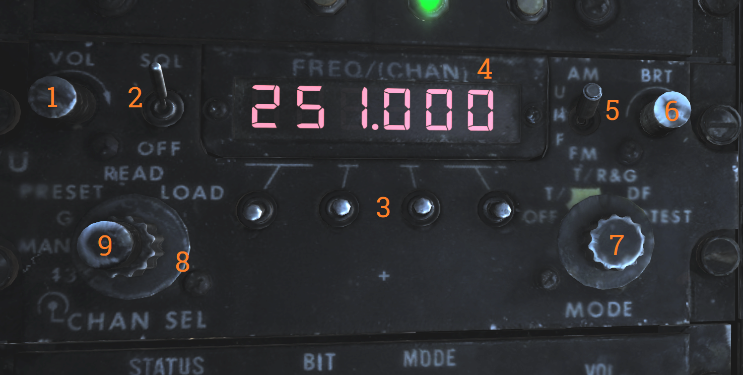 V/UHF radio 2. Radio and controls.
| No. | Control/Indicator | Function |
|---|---|---|
| 1 | VOL knob | Controls volume of V/UHF 2 audio to RIO headset. |
| 2 | SQL switch | ON/OFF switch enabling squelch. |
| 3 | Frequency select switches | Toggle switches selecting set frequency. |
| 4 | FREQ/(CHAN) display | Readout display showing selected frequency or channel. |
| 5 | UHF switch | Selector switch selecting modulation in use. Operational in the 225.000 to 399.00 MHz band. |
| 6 | BRT knob | Knob controlling display brightness. |
| 7 | MODE knob | MODE selector knob controlling V/UHF 2 radio mode. |
| 8 | Frequency mode knob | Outer dial on the knob, selects frequency mode. |
| 9 | CHAN SEL knob | Inner dial on the knob, selects preset channel to use. |
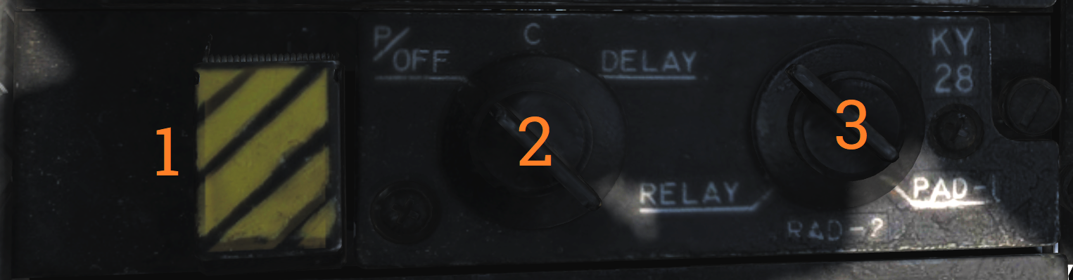
KY-28 Control Panel
| No. | Control | Function |
|---|---|---|
| 1 | ZEROIZE switch | Switch/guard used to zeroize KY-28. |
| 2 | Power-mode switch | Switch selecting KY-28 mode of operation. |
| 3 | Radio select switch | Switch selecting which radio to use with KY-28. |
Radar Beacon Control Panel
![]() Panel controlling AN/APN-154 radar beacon.
Panel controlling AN/APN-154 radar beacon.
| No. | Control/Indicator | Function |
|---|---|---|
| 1 | MODE selector | Selector switch controlling beacon mode of operation. SINGLE - Enables beacon response to single pulse codes. DOUBLE - Enables beacon response to set double pulse code. ACLS - Enables augmentor operation for ACLS. Required for CATCC radar lockon for ACLS. |
| 2 | ACLS TEST button | Button with green light used to indicate operation or test. When pressed with MODE in ACLS illumination indicates a successful test. The light also flashes when detecting an AN/SPN-42 radar sweeping past and illuminates when that radar has locked on for ACLS guidance. |
| 3 | PWR switch | Switch controlling beacon power. PWR - Enables beacon and all replies depending on MODE selector. STBY - Used to warm up the system, also enables ACLS replies if the MODE selector is set to ACLS. OFF - Beacon off. |
Liquid Cooling Control Panel
 LIQ COOLING switch controlling the liquid cooling system for the AWG-9 and AIM-54. The AWG-9 circuit can be enabled independently of the AIM-54. This switch needs to be enabled for the respective system before AWG-9 operation or AIM-54 missile preparation.
ICS Control Panel
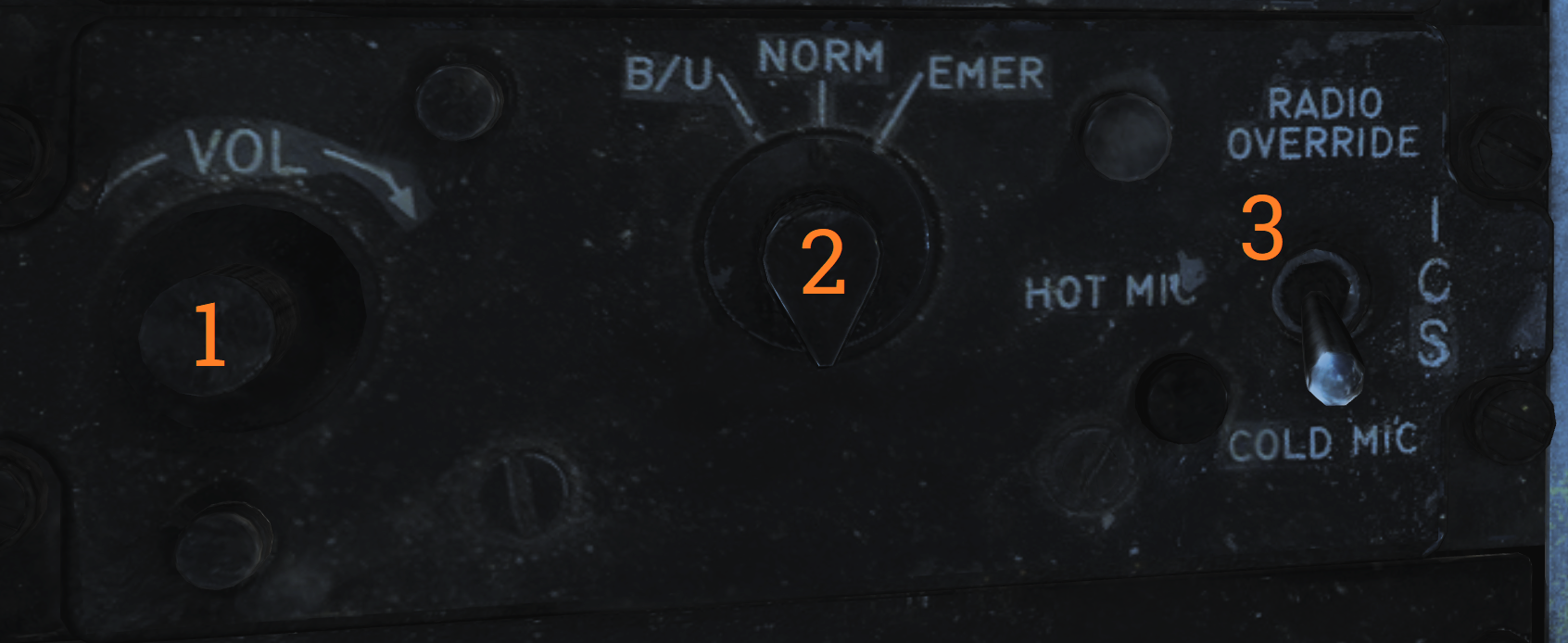 Control panel for ICS.
| No. | Control | Function |
|---|---|---|
| 1 | VOL knob | Volume control knob for intercommunication audio from the pilot to the RIO. |
| 2 | Amplifier selection knob | Knob selecting which amplifier to use for the RIO’s headset audio. |
| 3 | ICS switch | Selects ICS function. RADIO OVERRIDE - Makes ICS audio override radio audio. HOT MIC - Allows talking to the pilot without pressing the PTT. COLD MIC - Allows talking to the pilot only while the PTT is pressed. |
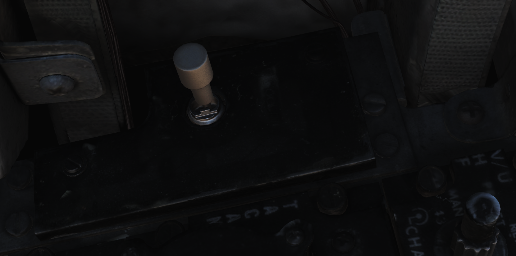
Eject Command Lever
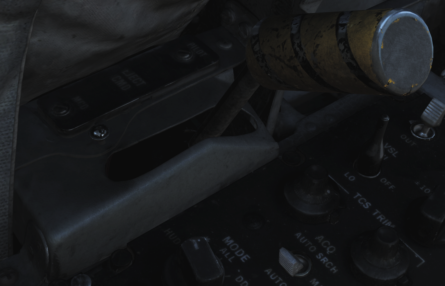 A pilot initiated ejection will always eject both crew members. The EJECT CMD lever controls what happens when the RIO ejects: In PILOT mode (lever forward), only the RIO will be ejected. In MCO mode, both pilot and RIO initiated ejection will eject both crew members.
Sensor Control Panel
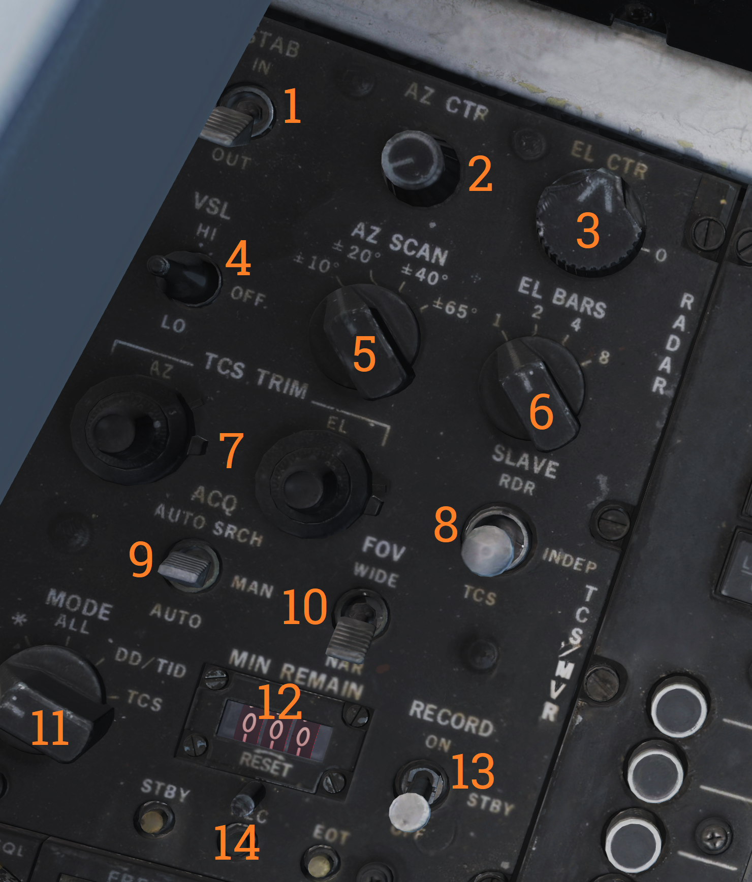 Control panel for AWG-9 scan settings, the TCS, and the airborne video tape recorder.
| No. | Control/Indicator | Function |
|---|---|---|
| 1 | STAB switch | Selector switch controlling ground stabilization of the radar. |
| 2 | AZ CTR knob | Azimuth control knob selecting the center of azimuth scan area. |
| 3 | EL CTR knob | Elevation control knob selecting the center of elevation scan area. |
| 4 | VSL switch | Selector switch spring-loaded to center which enables VSL. VSL HI or LO can be selected. |
| 5 | AZ SCAN knob | Azimuth scan knob selecting azimuth scan volume. |
| 6 | EL BARS knob | Elevation bar knob selecting the number of bars to scan in elevation. |
| 7 | TCS TRIM knobs | Trim knobs used to calibrate TCS video in azimuth and elevation. |
| 8 | SLAVE switch | Selector switch selecting which sensor is slaved to the other. |
| 9 | ACQ switch | Selector switch selecting acquisition mode for the TCS. AUTO, MAN or AUTO SRCH. |
| 10 | FOV switch | Selector switch selecting field of view for the TCS, WIDE or NAR (narrow). |
| 11 | MODE knob | Knob controlling what the AVTR records. |
| 12 | MIN REMAIN display | Counter showing minutes remaining for the AVTR. |
| 13 | RECORD switch | Selector switch controlling the AVTR. OFF/STBY/ON. |
| 14 | Indicator lights | Lights indicating AVTR operation. STBY, EOT (end of tape), and REC. |
Computer Address Panel
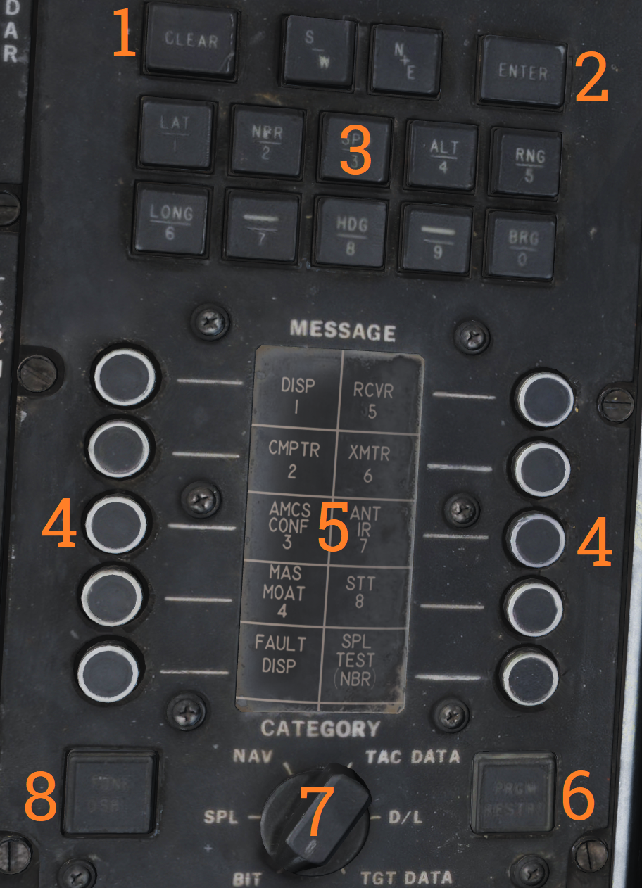 The CAP is used to enter data into the WCS. The MESSAGE indicator drum and buttons work similarly to the buttons on MFDs on newer aircraft.
| No. | Control/Indicator | Function |
|---|---|---|
| 1 | CLEAR button | Button clearing current TID buffer without inserting entered data. |
| 2 | ENTER button | Button inserting current data from TID buffer into the WCS. |
| 3 | Prefix & Numerical buttons | Numerical buttons with additional prefix selection functionality. |
| 4 | MESSAGE button switches | Buttons used to select functions from the MESSAGE drum. |
| 5 | MESSAGE indicator drum | Indicator drum used to indicate currently available MESSAGE functionality. |
| 6 | PRGM RESTRT button | Button used to restart the program running in the WCS. |
| 7 | CATEGORY knob | Selector knob selecting current category in use on the MESSAGE indicator drum. |
| 8 | TUNE DSBL | Non-functional. Note: All of the buttons have indicator lights indicating operation depending on function. |
Left Vertical Console
Armament Panel
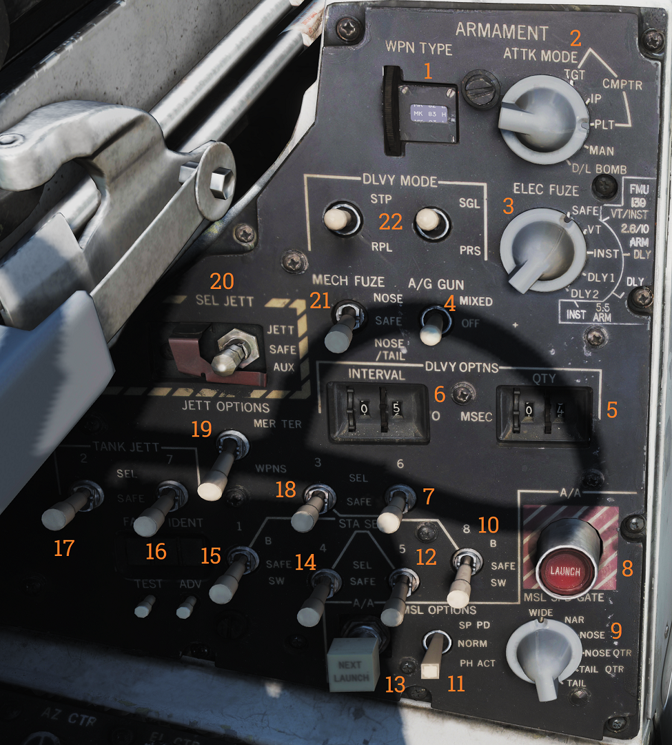 Main armament control panel in the RIO cockpit.
| No. | Control/Indicator | Function |
|---|---|---|
| 1 | WPN TYPE selector | Selector wheel selecting type of weapon used for WCS A/G calculation. |
| 2 | ATTK MODE knob | Knob selecting which A/G attack mode to use. |
| 3 | ELEC FUSE knob | Knob selecting electric fuse setting for A/G ordnance. |
| 4 | A/G GUN switch | Selector switch controlling gun mode in A/G master mode. MIXED enables the gun in addition to selected A/G ordnance. |
| 5 | QTY selectors | Selector wheels controlling quantity of A/G ordnance (including rockets) to be released. |
| 6 | INTERVAL selectors | Selector wheels controlling interval between weapons release in ripple delivery mode in milliseconds. |
| 7 | Station 6 select switch | Switch used to select station 6 for jettison or weapons A/G delivery. |
| 8 | A/A LAUNCH button | Button used for RIO launch of AIM-7 or AIM-54, hot trigger is indicated by button illumination. |
| 9 | MSL SPD GATE knob | Knob controlling the position of missile speed gate. |
| 10 | Station 8 select switch | Switch used to select station 8 for jettison or weapons A/G delivery. B selects the lower pylon for release or jettison, the SW option is non-functional. |
| 11 | MSL OPTIONS switch | Selector switch used to activate AIM-7 pulse doppler mode or AIM-54 active launch mode. |
| 12 | Station 5 select switch | Switch used to select station 5 for jettison or weapons A/G delivery. |
| 13 | NEXT LAUNCH button | Button used by RIO to select a hooked target as the next target to launch at in TWS. |
| 14 | Station 4 select switch | Switch used to select station 4 for jettison or weapons A/G delivery. |
| 15 | Station 1 select switch | Switch used to select station 1 for jettison or weapons A/G delivery. B selects the lower pylon for release or jettison, the SW option is non-functional. |
| 16 | TANK JETT station 7 switch | Switch selecting station 7 for tank jettison. |
| 17 | TANK JETT station 2 switch | Switch selecting station 2 for tank jettison. |
| 18 | Station 3 select switch | Switch used to select station 3 for jettison or weapons A/G delivery. |
| 19 | JETT OPTIONS switch | Switch selecting whether to jettison only WPNS (weapons) or MER/TER (weapon racks) in addition to weapons. Non-functional in modeled F-14. |
| 20 | SEL JETT switch | Selector switch used to jettison selected stations in normal (JETT) mode or AUX (backup) mode. The AUX position is guarded. |
| 21 | MECH FUSE switch | Selector switch used to enable and set which mechanical fuse to use for A/G ordnance. |
| 22 | DLVY MODE switches | Two selector switches used to select A/G delivery mode. One switch controls whether to release in singles or pairs and the other sets whether to release once or multiple times according to settings. |