Center Console
Tactical Information Display (TID)
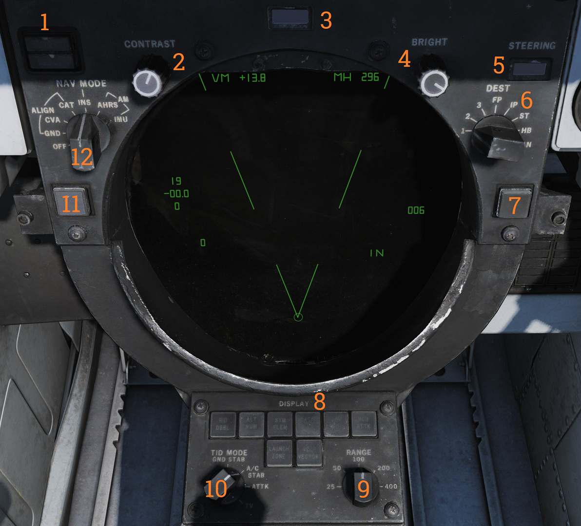 Tactical information display and corresponding and navigational controls.
| No. | Control/Indicator | Function |
|---|---|---|
| 1 | INS status indicator | Indicator light showing the status of the INS during alignment. STBY indicates power applied but not aligned. READY indicates minimum launch criteria for AIM-54. Both lights turn off when INS mode is selected. Can otherwise indicate faults. |
| 2 | CONTRAST knob | Control knob that controls the contrast of TCS video. |
| 3 | DATA READOUT drum | Readout drum indicating the source of the data displayed on the TID readouts. Might be blank for sources not having their own text on the drum. |
| 4 | BRIGHT knob | Control knob controlling TID brightness. |
| 5 | STEERING indicator drum | Readout drum indicating current steering information being displayed to the pilot. |
| 6 | DEST selector | Selector knob controlling what destination to use for the navigation destination mode. |
| 7 | CLSN button | Button with indication used to select collision steering towards a tracked target or TWS centroid. |
| 8 | DISPLAY buttons | Buttons controlling what elements are shown on the TID. Contains indicator lights showing selection. |
| 9 | RANGE selector | Selector switch selecting the current scale of the TID. Corresponds to the distance the diameter represents. |
| 10 | TID MODE selector | Selector switch controlling current TID presentation. |
| 11 | TRACK HOLD button | Button extending the amount of time before a track is dropped after the last radar observation to two minutes. Normal time is 14 seconds. |
| 12 | NAV MODE selector | Selector switch controlling navigation reference systems. Controls which system is in use and also alignment of the INS. |
Hand Control Unit (HCU)
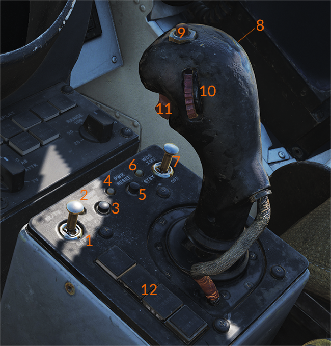 Main radar and TCS control stick.
| No. | Control/Indicator | Function |
|---|---|---|
| 1 | IR/TV switch | Switch controlling TCS power. Enables selection of OFF/STBY and ON. |
| 2 | IR/TV overtemp indicator | Light indicating the presence of an overtemperature condition in the TCS. |
| 3 | LIGHT TEST button | Button allowing a test of all AWG-9 lights. |
| 4 | PWR RESET indicator | Light indicating one or more inoperative secondary power supplies. |
| 5 | PWR RESET button | Button allowing a reset of inoperative secondary power supplies. If the condition triggering the inoperational state remains the affected supplies will remain inoperational. |
| 6 | WCS indicator | Light indicating selection of STBY or XMT with the radar not yet timed out or selection of XMT with radar transmission remaining off. |
| 7 | WCS switch | Switch controlling WCS power (computer and radar). STBY turns on power to the WCS and begins radar warmup without transmission. XMT enables radar transmission if the radar is ready. Display warmup time is 30 seconds, radar warmup is 3 minutes. |
| 8 | MRL button | Button selecting manual rapid lockon mode. Overrides all operational modes except PLM and VSL. |
| 9 | OFFSET button | Button used to offset TID to hooked location on the display. |
| 10 | ELEV thumbwheel | Thumbwheel used to fine-tune elevation of the radar antenna for STT lockon acquisition. |
| 11 | HCU trigger | Used to select and trigger different functions in the WCS depending on current mode and HCU function. First detent is HALF ACTION, second detent is FULL ACTION. Examples of use are target acquisition and symbol hook. |
| 12 | Hand control function buttons | Buttons with an indication used to control the function of the HCU stick. Mutually exclusive. IR/TV - Selects control of TCS azimuth, elevation, and tracking. Enables display of TCS elevation on the right elevation indicator on DDD. RDR - Selects control of radar antenna for STT lock-on and return to search if already in STT. Enables display of currently commanded radar antenna elevation on the right elevation indicator on DDD. DDD CURSOR - Selects control of DDD cursor used to mark a geographical position while in pulse radar mode. TID CURSOR - Selects control of TID cursor used to hook (select) symbols on the TID. |