F-14 Manual

Contents
- Introduction
- Cockpit Overview
- Systems Overview
- Weapons & Stores
- Jester
- Normal Procedures
- Emergency Procedures
- DCS
- Abbreviations
- Imprint
This document is available online, as PDF version, embedded in-game as offline website and can be contributed to as open-source project at GitHub.
Introduction
Dear Reader,
we are proud to present to you the Heatblur Simulations F-4E Phantom II for Digital Combat Simulator. We’ve spent years of development and countless hours of research to bring you the most in-depth recreation of this legendary aircraft ever made. You will be able to fly your Phantom both as a pilot and WSO, alone with the JESTER-AI - your own WSO AI - or in multiplayer together with a friend.

But not only did we recreate the Phantom’s flight model, systems, avionics, radar, RWR and weapons delivery faithfully, we also tried to innovate our approach to flight simulation in general with the module, laying important groundwork for our future modules and as always trying to push the boundaries of flight simulation just a little bit further. From small quality of life improvements like being able to write on your canopy, to an interactive crew chief, our Phantom also utilizes our next-gen components based simulation framework - the aircraft is simulated as a connection of thousands of individual components. From an instrument needle to control surfaces, each component influences the state of the aircraft and even comes with its own wear and tear. From simulating accurate power draw from the power source to the smallest light bulb and all the nodes along the way, from hydraulic fluid which moves the hydraulics which in turn move the flight surfaces all the way to a mass physics based model - things now happen naturally, influenced by each other, and not scripted anymore. Whether that means that unstable power draw may cause a lamp to flicker, or that you can deploy your landing gear in case of a failure using gravity, or that correct and incorrect use of the aircraft influences the wear and tear of each single component individually - we never before attempted a simulation as deep as with the F-4E Phantom II. The DCS: F-4 represents some of the most immersive cold war fighter jet simulation available!
Such innovation and in depth simulation will present an increased learning curve for users. This is why it was important for us to also innovate on the side of learning tools available to you, starting with this manual, so that our modules are accessible to the casual simmer and aficionado alike. You can open the manual in flight, and read along, but better still, you can click any switch (with an input combo) in flight and the manual will open in the correct chapter, explaining the switch or system in the cockpit, all while you are bolting through the air in your thunderous jet. We also changed the underlying structure of the manual to move to an open source model. This will allow the community to easily contribute via GitHub, as two heads (or thousands of them) think better than one. As an added benefit, readability for the mobile version will be greatly improved as well. We have hyperlinked many items for you, providing easy navigation between cockpit diagrams and system overviews. Also featured in the manual are numerous checklists and procedures, and a "Lessons" section, which is planned to be featured with the Early Access Release of the Phantom. The fully written out lessons will complement the flyable training missions. The training missions are now tailored to be learned together with the written lesson in the manual, you will be able to revert steps in the training mission, able to read along and pause (no more restarting for missed items). With all of these features at your disposal, you will be able to adequately prepare yourself for your training. And best of all, during your training you will be instructed by real life F-4 pilots and a real life F-4 WSO Instructor! Who else could teach you better?
We hope you will enjoy both learning and flying the F-4E Phantom II - dive as deep as your heart desires. For this exciting journey we wish you good luck and many fun adventures, and of course: always check six!
In the name of the entire Heatblur Team,
Nicholas Dackard, Heatblur Simulations, CEO and Founder
Definitions
Should an acronym, such as DSCG be unclear at any point, look it up in the exhaustive list provided at the Abbreviations chapter.
The following symbology is used throughout this manual.
General
| Symbol | Meaning | Description |
|---|---|---|
| 💡 | Note | Item that is given special emphasize |
| 🟡 | Caution | Should be followed to prevent damage to equipment |
| 🔴 | Warning | Ignoring might lead to personal injury or loss of life |
| 🚧 | Under Construction | A section is work in progress and will be improved still |
Checklists
| Symbol | Description |
|---|---|
| Bold | Step is necessary to be performed OR it's a bold face procedure (crewmembers should be able to accomplish bold face procedures without reference to the checklist) |
| 🔧 | Step involves or may involve crew chief interaction |
| ⚡ | Step cannot be performed when battery start is made, external power is necessary |
Historical Background
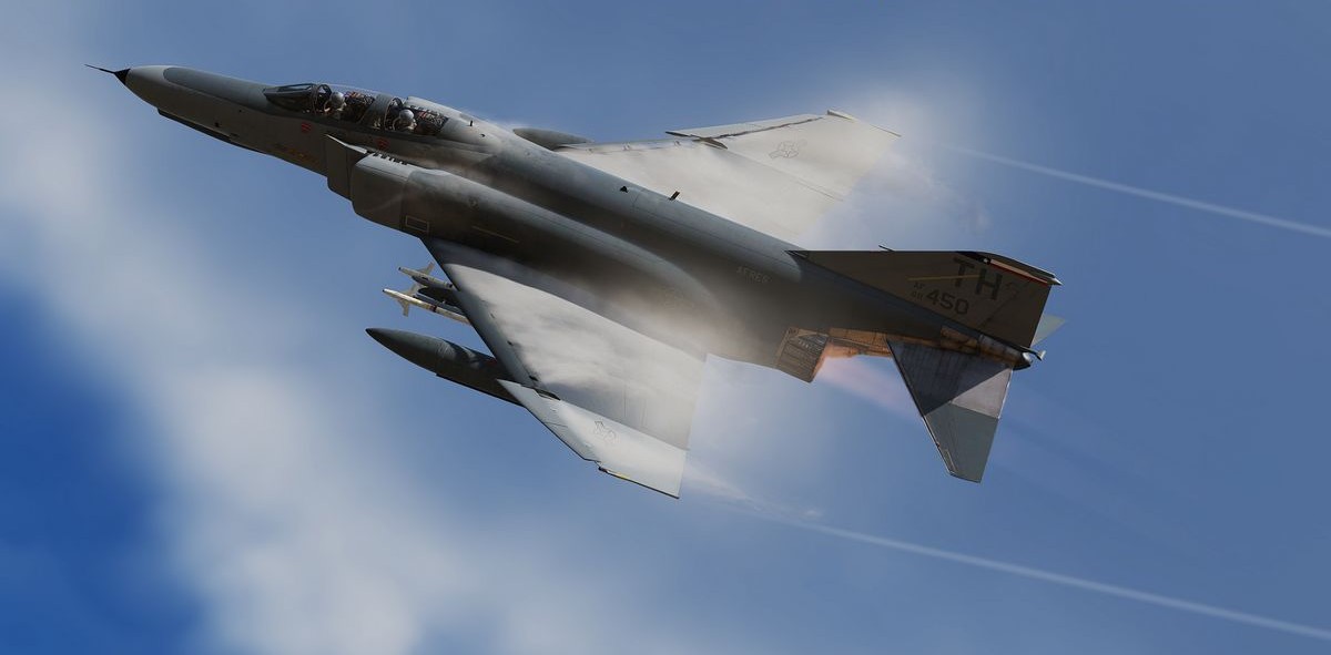
F-14 Tomcat
 U.S. Navy photo by LT J.G. Thomas Prochilo. (DN-SC-83-06680)
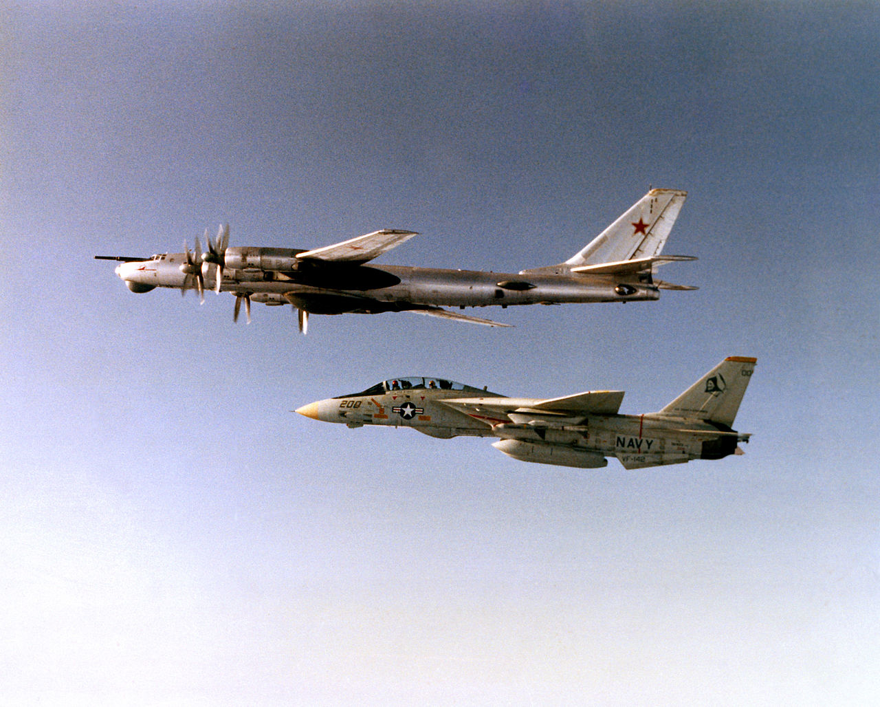
The F-14 Tomcat can trace its origin back to the 1950’s and the US Navy’s need for a carrier based long range interceptor to fill the Fleet Air Defence role. It was decided that it needed an aircraft with a more advanced and longer ranged radar as well as longer ranged air-to-air missile than the F-4 Phantom.
The Navy was directed, by then defense secretary Robert McNamara, to join the Tactical Fighter Experimental or TFX program to procure this aircraft in a joint venture with the US Air Force. The Navy was opposed to this from the beginning and the proposed General Dynamics F-111B did not meet the Navy’s expectations.
Grumman, which had been brought on board by General Dynamics for the Navy F-111B, was eventually awarded a contract to begin development of an aircraft more suited to the Navy’s requirements. This led to the design that would eventually become the F-14, carrying over the radar (AN/AWG-9) and missiles (AIM-54 Phoenix) from the failed F-111B project.
The F-14 Tomcat first flew on the 21st of December 1970 and entered service on the 22nd of September 1974. The name “Tomcat” follows Grumman’s tradition of naming their aircraft after cats and also partially from the nickname “Tom’s Cat” for Vice Admiral Thomas F. Connolly who was instrumental for the development of the F-14.
Service Life Upgrades
The first version of the F-14, the F-14A was equipped with the Pratt & Whitney TF30 and carried an IRST system in the chinpod under the nose.
The TF30 engines were generally regarded as temperamental and underpowered for the F-14A and were eventually replaced by the General Electric F110-400 engines in the F-14A+ (later F-14B).
The IRST system was rather quickly determined to be underperforming and replaced with the TCS (Television Camera Set) in the chinpod allowing for greater than visual range identification of radar tracked targets.
Both the F-14A and F-14B received continuous upgrades during their life, including new programmable cockpit displays (PTID and PMDIG) as well as a new INS system, a digital flight control system (DFCS) and an RWR system amongst others.
Eventually, the Tactical Reconnaissance mission was also added to the F-14’s portfolio, enabled by the TARPS system, allowing the Tomcat to gather photographic reconnaissance material.
Ground Attack
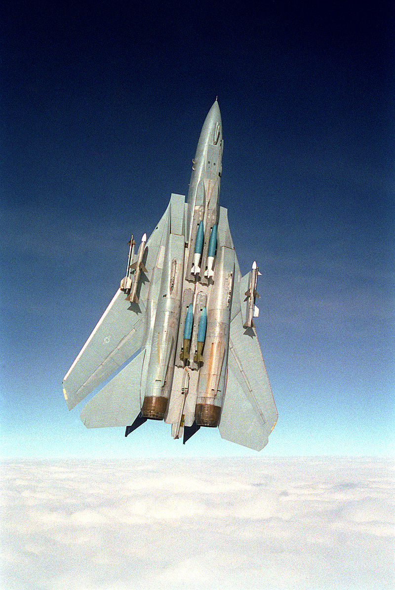 Photo by LCDR Dave Parsons. (DN-SC-93-01299)
During the 1990’s when the aerial threat to the fleets of the US Navy lessened and with the advent of operations like Desert Storm, the ground attack role was resurrected.
The ability to carry and deliver air-to-ground munitions had been implemented in the F-14 from the beginning but ruled out by the Navy as cost and risk ineffective given the F-14’s role as a Fleet Air Defence fighter.
With the renewed interest for this role, some of the F-14As and F-14Bs were equipped to carry the LANTIRN targeting pod allowing the RIO to find and designate laser guided bombs for his own aircraft and others. Later on the ability to carry and deliver gps-guided JDAMs was also added.
Most of the LANTIRN equipped aircraft were the ones upgraded with the programmable TID or (PTID) allowing for greater integration of the LANTIRN.
F-14D
In the 1990’s the ultimate F-14 version was beginning to see service, the F-14D.
The F-14D used the same engines as the F-14B, the GE F110-400s in addition to using the digital flight control system, which was eventually retrofitted into operational F-14As and F-14Bs as well.
In addition, the F-14D also had a newer, more advanced version of the AN/AWG-9, the AN/APG-71, as well as a whole suite of upgraded avionics along with a new chinpod combining the TCS with a new, improved IRST system.
End of Service
The F-14 Tomcat did eventually show its age, forcing the Navy to retire it due to increased maintenance costs and the general status of the now dated airframes. Additionally, the Tomcat’s primary role, the Fleet Air Defence role, seemingly disappeared with the end of the Cold War.
The Tomcat was finally retired in a ceremony on the 22nd of September 2006 at NAS Oceana.
Iran
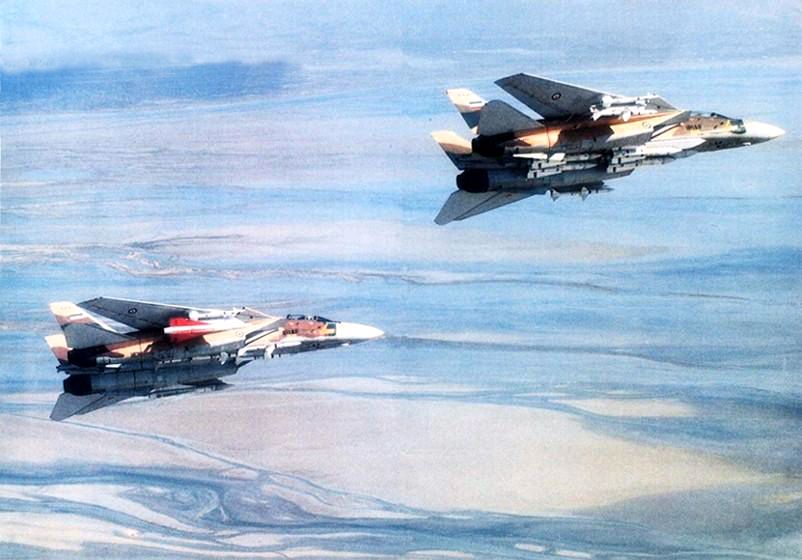 IRIAF photo circa 1986.
The only other operator of the F-14 Tomcat was the Imperial Iranian Air Force, later the Islamic Republic of Iran Air Force, for which the Shah of Iran, Mohammad Reza Pahlavi acquired 80 Tomcats.
The eventual fall of the Shah and the rise of the Islamic Republic of Iran meant that a country now opposed to the United States had access to one of its most advanced fighter aircraft. This meant that the Iranian F-14s now lost access to new spare parts and missiles, apart from black market sources, greatly increasing the difficulty of maintaining the aircraft.
The F-14 Tomcat was used during the Iran-Iraq war, claiming a great number of air-to-air victories over the Iraqi Air Force, with some sources going so far as to claim that Iraqi pilots at times left the contested air space to avoid facing the AN/AWG-9 - AIM-54 combo.
To this date the IRIAF continues to fly the F-14 Tomcat as the sole operator. It’s not entirely known how the Iranians source their spare parts but it’s assumed that they’ve had to cannibalize inoperable aircraft to keep a portion of their fleet flying. In addition, rumours exist mentioning black market sources as well as indigenous production of some parts.
The Iranian operated Tomcats are of the earlier F-14A revisions, using the TF30 engines and lacking a TCS or IRST system.
AIM-54 Phoenix
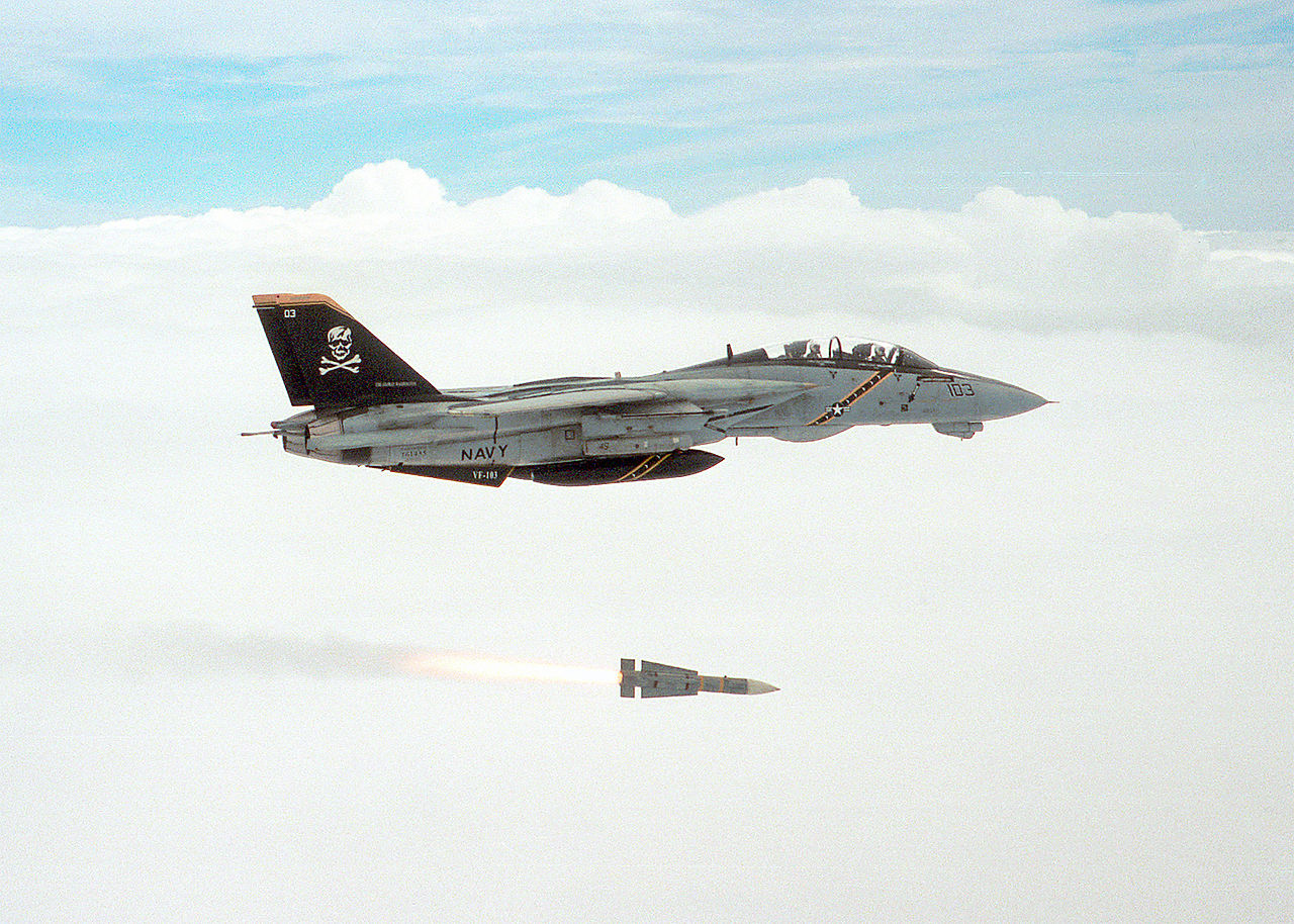 U.S. Navy photo by Capt. Dana Potts. (020924-N-1955P-001)
The AIM-54 long-range air-to-air missile was born from the same TFX program as that which eventually led to the F-14 Tomcat.
It was designed for the F-111B and then adopted for the F-14 as a long-range missile capable of long range engagement of enemy bombers in addition to hostile cruise missiles. That’s not to say that the AIM-54 Phoenix was a slouch at engaging other smaller targets as well.
Outstanding features of the AIM-54 missiles were their long range as well as their ability to be launched at up to six simultaneous targets, guided first by the AN/AWG-9 radar in the launching aircraft and then its own active radar seeker independently.
The original AIM-54 Phoenix was the AIM-54A with a mk47 rocket motor. The motor was later on upgraded, creating the mk60 motor, increasing the missile’s range. Eventually the AIM-54 itself was also upgraded, resulting in the AIM-54C with, amongst other things, an upgraded seeker head and a newer version of the mk47 producing less smoke, making the missile hard to spot visually.
The US Navy fired only three AIM-54 missiles in combat, all three over Iraq. The missiles never hit their intended targets though as two of the missiles’ rocket motors failed with the third also missing its target as it turned tail and ran.
While little is known for certain in the western hemisphere, the IRIAF claims at least 78 air-to-air victories using the AIM-54 against Iraqi MiG-21s, MiG-23s, MiG-25s, Mirage F-1s, Super Etendards and even some anti-ship cruise missiles.
F-4E Air to Air Kills
The F-4E Phantom II, an upgraded version of the F-4 Phantom series, played a significant role in air-to-air combat during the Vietnam War. Equipped with the AIM-7 Sparrow missile, a radar-guided weapon with beyond-visual-range capabilities, the F-4E had a notable advantage in engagements.
In Vietnam, F-4E pilots engaged in dogfights against various enemy aircraft. The Sparrow missile allowed them to target adversaries from a distance, contributing to the aircraft's success. Key USAF pilots, such as Steve Ritchie and Chuck DeBellevue, achieved ace status by securing five or more air-to-air victories.
The total number of air-to-air kills attributed to the F-4E Phantom II, combining both the USAF and USN, is estimated to be around 21 during the Vietnam War, including 4 MiG-19s and 17 MiG-21s. However, this figure may vary across sources. In total, F-4C/D/E Variants shot down 107 MiG jets, rewarding it the nickname "Biggest distributor of MiG parts".
Despite its effectiveness, the F-4E faced challenges in close-quarters combat due to the initial absence of an internal cannon. Modifications, including the addition of an M61 Vulcan cannon, addressed this limitation and improved the aircraft's performance in close-range engagements.
The success of the F-4E Phantom II in Vietnam solidified its reputation as a versatile and formidable fighter, and it continued to serve in air forces worldwide for many years.
 a Marine F-4
Phantom II from Marine Fighter/Attack Squadron 314 firing an AIM-7 Missile
a Marine F-4
Phantom II from Marine Fighter/Attack Squadron 314 firing an AIM-7 Missile
USAF
In detail, the USAF confirmed 21 kills.
| Kills | Aircraft |
|---|---|
| 17 | MiG-21 |
| 4 | MiG-19 |
Scored with the following weapons:
| Kills | Weapon |
|---|---|
| 10 | AIM-7 |
| 5 | AIM-9 |
| 5 | Gun |
| 1 | Maneuver |
IAF
In combat, the Israeli Air Force downed 116 jets.
| Kills | Aircraft |
|---|---|
| 81 | MiG-21 |
| 14 | MiG-17 |
| 14 | Mi-8 |
| 5 | Su-7 |
| 1 | AS-5 |
| 1 | IL-28 |
Scored with the following weapons:
| Kills | Weapon |
|---|---|
| 44 | AIM-9 |
| 33 | Gun |
| 32 | Maneuver or Unspecified |
| 7 | AIM-7 |
IRIAF
The IRIAF shot down 83 aircraft.
| Kills | Aircraft |
|---|---|
| 29 | MiG-21 |
| 21 | MiG-23 |
| 19 | Su-20/22 |
| 2 | An-24 |
| 2 | Mi-25 |
| 2 | Mirage F1 |
| 1 | Hunter |
| 1 | Tu-22 |
| 1 | Mirage 5 |
| 1 | Bell 412 |
| 1 | SA 321 |
| 1 | Unidentified |
Scored with the following weapons:
| Kills | Weapon |
|---|---|
| 46 | AIM-9 |
| 22 | Maneuver or Unspecified |
| 9 | Gun |
| 6 | AIM-7 |
F-4E First Flights by Nation
The F-4 was used widely by several NATO and allied countries. Because of that it reached many first flight milestones in the various countries.
| Nation | McDonnell Number | BuNo/USAF Serial | Date |
|---|---|---|---|
| United States | 2234 | 66-284 | June 30th, 1967 |
| Israel | 3492 | 68-396 | May 26th, 1969 |
| Australia | 3847 | 69-0304 | June 26th, 1970 |
| Japan | 4037 | 69-7463 | January 14th, 1971 |
| Iran | 4093 | 69-7711 | March 2nd, 1971 |
| Greece | 4439 | 72-01500 | January 29th, 1974 |
| Turkey | 4525 | 73-01016 | June 17th, 1974 |
| Germany | 4946 | 75-00628 | May 5th, 1977 |
| South Korea | 4966 | 76-0493 | July 28th, 1977 |
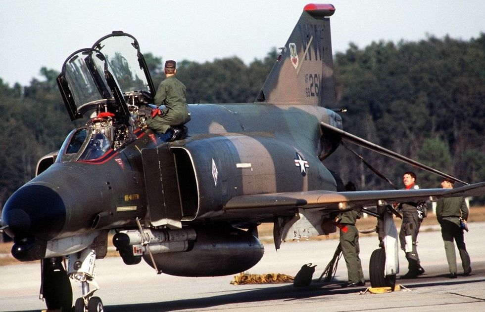 The crew of an F-4 Phantom II aircraft completes a post-flight inspection
Technical Specifications: F-14 Tomcat
F-14A Technical Specifications
| Item | Description |
|---|---|
| Wingspan (Fully Extended) | 64’ 1.5" (~19.5 meters) |
| Wingspan (Fully Swept Airborne) | 38’ 2.5" (~11.6 meters) |
| Wingspan (Oversweep) | 33’ 3.5" (~10.1 meters) |
| Length | 62’ 8.5" (~19.1 meters) |
| Height | 16' (~4.9 meters) |
| Wing Area | 565 sqft (~52.5 m²) |
| Empty Weight | 40,104 lb (~18,200 kg) |
| Maximum Weight | 72,000 lb (~32,700 kg) |
| Maximum Thrust, Dry | 34,154 lbf (152 kN) |
| Wing Loading | 92 lb/ft² (449.2 kg/m²) |
| Maximum Speed | 1,544 mph (~2,500 km/h) Mach 2.38 |
| Ceiling | 50,000'+ (~15,200 meters) |
| Range | 1,730 NM (~3200 km) |
F-14B Technical Specifications
| Item | Description |
|---|---|
| Wingspan (Fully Extended) | 64’ 1.5" (~19.5 meters) |
| Wingspan (Fully Swept Airborne) | 38’ 2.5" (~11.6 meters) |
| Wingspan (Oversweep) | 33’ 3.5" (~10.1 meters) |
| Length | 62’ 8.5" (~19.1 meters) |
| Height | 16' (~4.9 meters) |
| Wing Area | 565 sqft (~52.5 m²) |
| Empty Weight | 41,780 lb (~19,000 kg) |
| Maximum Weight | 74,349 lb (~33,700 kg) |
| Maximum Thrust, Dry | 56,400 lbf (251 kN) |
| Wing Loading | 94 lb/ft² (458.9 kg/m²) |
| Maximum Speed | 1,544 mph (~2,500 km/h) Mach 2.38 |
| Ceiling | 53,000'+ (~16,200 meters) |
| Range | 2,050 NM (~3800 km) |
-- --US F-14 airframes undergoing modification and upgrade
Cockpit Overview
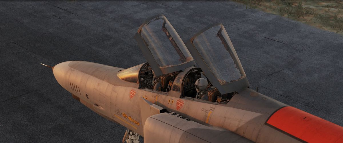
Greetings, phabulous Crewmen! Get ready for an in-depth look into the cockpit of the F-4E Phantom II by Heatblur.
The following chapter gives a detailed overview of the Pilots cockpit, as well as the Weapons Systems Officer (WSO) Pit. Each single switch will be outlined and explained briefly, while giving context to the functions.
More in-depth details on the various systems and consequences of using a switch beyond their brief explanation are available in the 3. Systems Overview Chapter.
"Step right up there and take a look. We got all kinds of amenities on these babies."
Pilot Cockpit Overview
Layout
Left Side Console
G-valve Button
 Pressed to test inflation of g-suit.
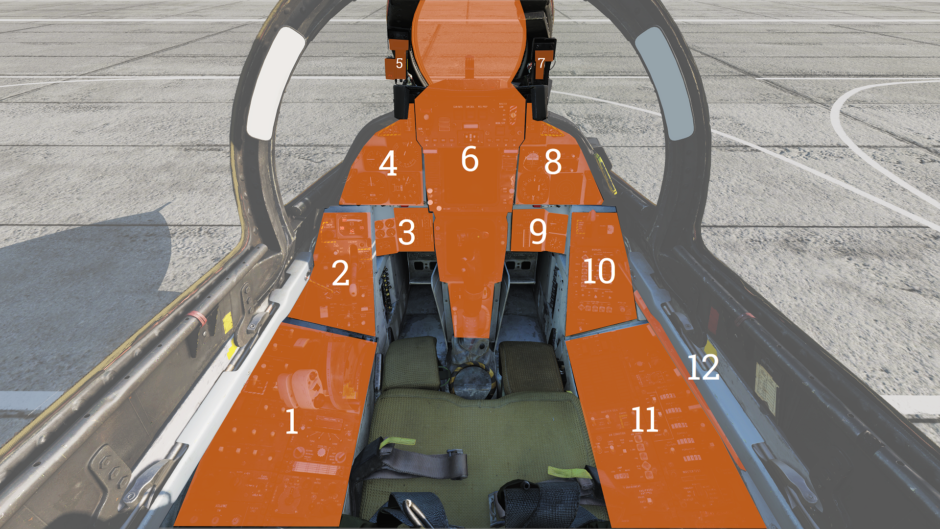
Oxygen-Vent Airflow Control Panel
 Controls ventilation airflow to pressure suit or seat
cushions and oxygen to pilot mask.
Controls ventilation airflow to pressure suit or seat
cushions and oxygen to pilot mask.
| No. | Control | Function |
|---|---|---|
| 1 | VENT AIRFLOW dial | Used to control airflow through the pressure suit or seat cushions if no pressure suit is worn. |
| 2 | OXYGEN switch | Switch with ON/OFF positions. Controls oxygen flow to the mask. |
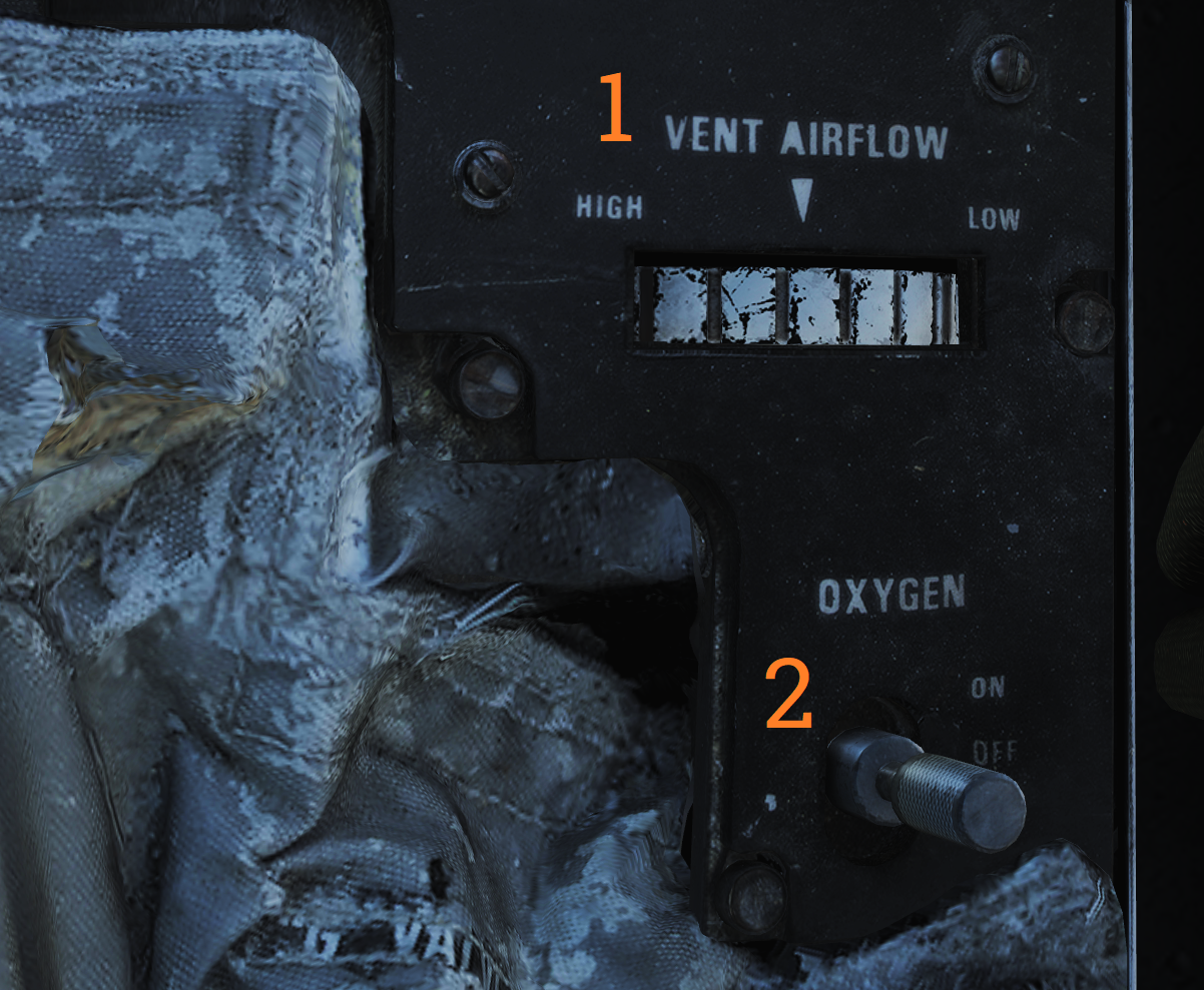
Volume/TACAN Command Panel
 Panel controlling volume to Pilot headset and crewmember in control
of TACAN.
Panel controlling volume to Pilot headset and crewmember in control
of TACAN.
| No. | Control/Indicator | Function |
|---|---|---|
| 1 | ALR-67 knob | Controls audio volume from the ALR-67 to the pilot. |
| 2 | SW knob | Controls volume of Sidewinder audio tone to the pilot. |
| 3 | V/UHF 2 knob | Controls volume of audio from AN/ARC-182 to the pilot. |
| 4 | TACAN CMD switch | Sets crewmember in command of the TACAN. Also indicates current setting. |
TACAN Control Panel
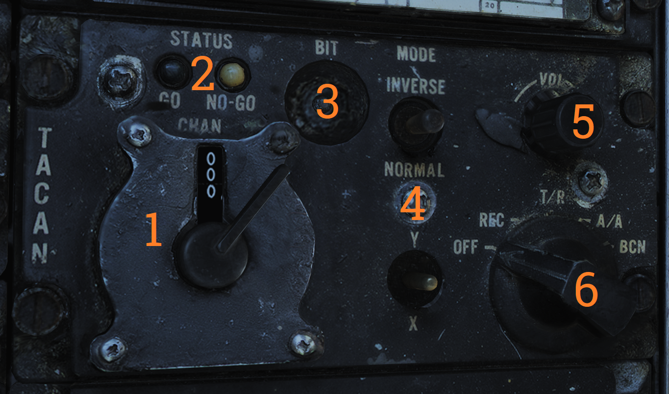 TACAN control panel letting the pilot control TACAN if in command of
it.
TACAN control panel letting the pilot control TACAN if in command of
it.
| No. | Control/Indicator | Function |
|---|---|---|
| 1 | Dual rotary switch | Outer dial selects first two digits and inner dial selects last digit for TACAN channel selection. |
| 2 | GO & NO-GO lights | Lights indicating result of TACAN BIT. |
| 3 | BIT button | Button initiating TACAN BIT. |
| 4 | MODE switches | Switches mode for TACAN operation and selects X or Y channels. INVERSE mode not functional. |
| 5 | VOL knob | Volume control knob for TACAN audio to the pilot. |
| 6 | Mode knob | Selects TACAN mode (OFF, REC, T/R, A/A, BCN). |
ICS Control Panel
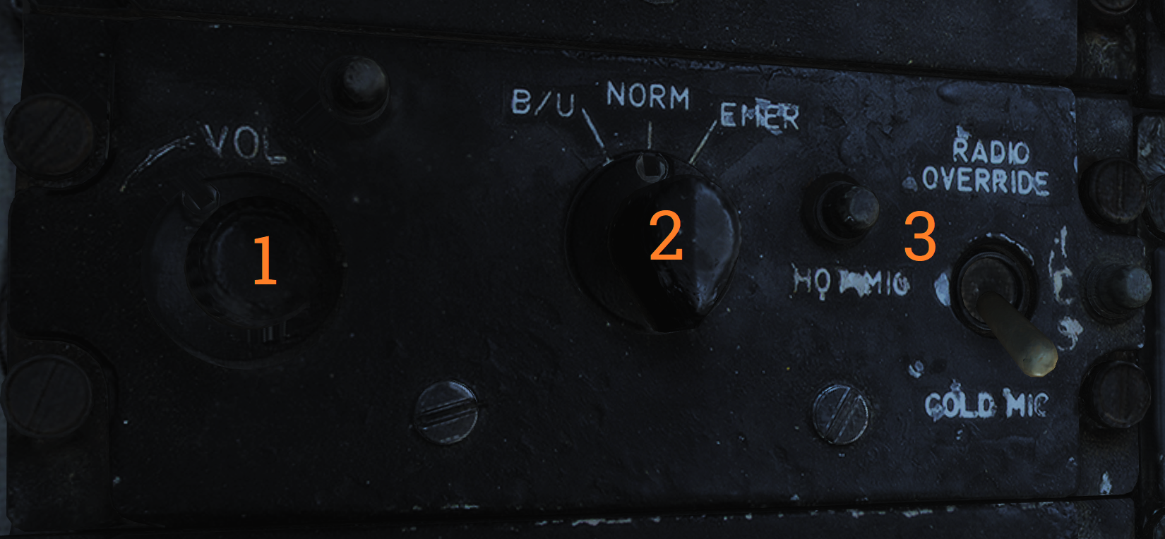 Control panel for ICS.
| No. | Control | Function |
|---|---|---|
| 1 | VOL knob | Volume control knob for intercommunication audio from the RIO to the pilot. |
| 2 | Amplifier selection knob | Knob selecting which amplifier to use for pilot’s headset audio. |
| 3 | ICS switch | Selects ICS function. RADIO OVERRIDE - Makes ICS audio override radio audio. HOT MIC - Allows talking to the RIO without pressing the PTT. COLD MIC - Allows talking to the RIO only while the PTT is pressed. |
AFCS Control Panel
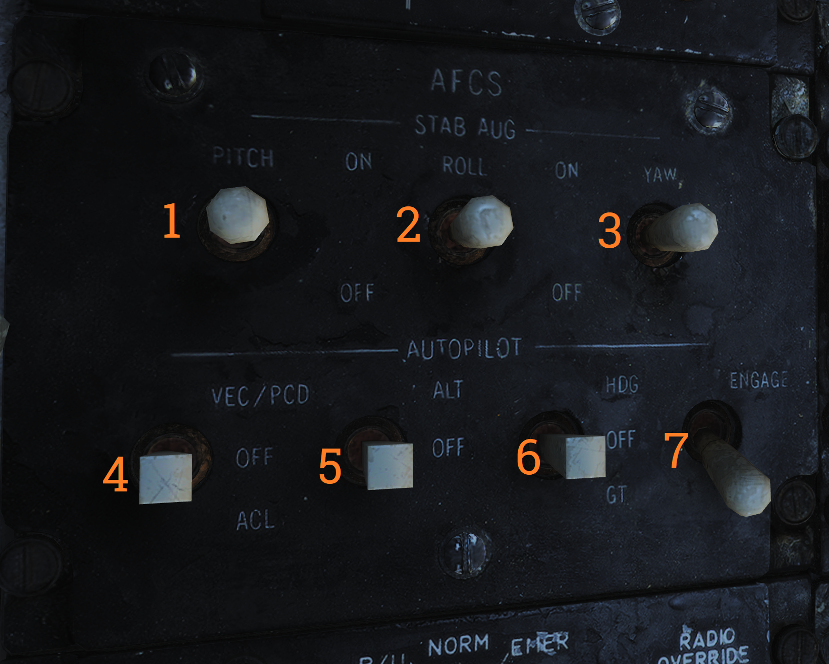 Control panel for AFCS and autopilot.
| No. | Control | Function |
|---|---|---|
| 1 | PITCH switch | Enables pitch stability augmentation. |
| 2 | ROLL switch | Enables roll stability augmentation. |
| 3 | YAW switch | Enables yaw stability augmentation. |
| 4 | VEC/PCD/ACL switch | Switch controlling the remote control modes of autopilot. |
| 5 | ALT switch | ON/OFF switch, enables altitude hold. Engaged by NWS button on pilot stick. |
| 6 | HDG switch | Selects HDG hold mode. |
| 7 | ENGAGE switch | ENGAGE/OFF. Engages autopilot. Note: All switches are spring-loaded to OFF position but held in position with solenoid to enable automatic disengagement when applicable. |
UHF 1 (AN/ARC-159) Radio
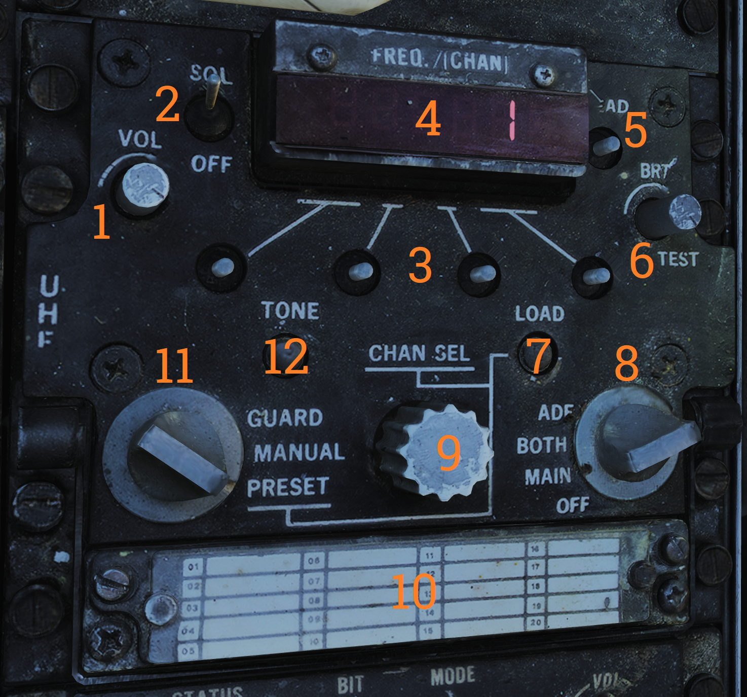 UHF radio 1. Radio and controls.
| No. | Control/Indicator | Function |
|---|---|---|
| 1 | VOL knob | Controls volume of UHF 1 audio to pilot headset. |
| 2 | SQL switch | ON/OFF switch enabling squelch. |
| 3 | Frequency select switches | Toggle switches selecting set frequency. |
| 4 | FREQ/(CHAN) display | Readout display showing selected frequency or channel. |
| 5 | READ button | Button toggling display of selected channel while held. |
| 6 | BRT knob | Knob controlling display brightness. |
| 7 | LOAD button | Button toggling load of set frequency to set channel. |
| 8 | Function selector knob | Selector knob selecting radio function (ADF, BOTH, MAIN, OFF). |
| 9 | CHAN SEL knob | Selects preset channel to use. Preset channels chart used to record frequencies or use for preset channels. |
| 10 | Mode selector knob | Knob selecting radio frequency select mode. |
| 11 | TONE button | Transmits a TONE on current frequency. |
ASYM Limiter/Engine Mode Select (F-14B only)
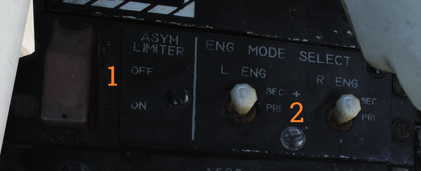 Control panel for the asymmetric thrust limiter system and the control
mode of each engine.
Control panel for the asymmetric thrust limiter system and the control
mode of each engine.
| No. | Control | Function |
|---|---|---|
| 1 | ASYM LIMITER switch | ON/OFF switch enabling afterburner thrust asymmetry limiter. |
| 2 | ENG MODE SELECT switches | Switches selecting engine mode for their respective engine (PRI, SEC). |
Target Designate Switch
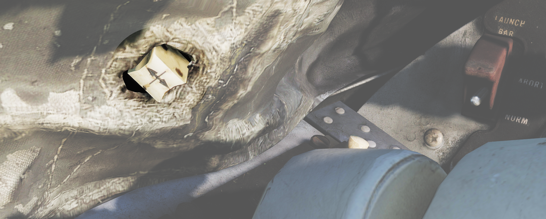 Used to designate ground targets on the HUD and to control pilot ACM
radar modes except PLM. Can be moved up/down and forward which is the designate position.
Used to designate ground targets on the HUD and to control pilot ACM
radar modes except PLM. Can be moved up/down and forward which is the designate position.
Inlet Ramps/Throttle Control Panel
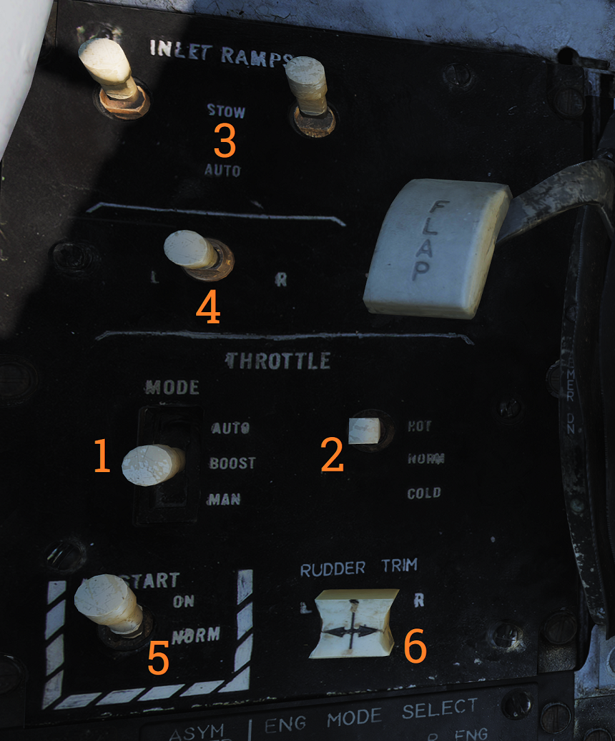 Control panel for various engine systems, throttle settings and rudder
trim.
Control panel for various engine systems, throttle settings and rudder
trim.
| No. | Control | Function |
|---|---|---|
| 1 | THROTTLE MODE | Switch selecting throttle operation mode (AUTO, BOOST, MAN). |
| 2 | THROTTLE TEMP | Switch selecting throttle computer gain (HOT, NORM, COLD). |
| 3 | INLET RAMPS | Switches selecting operational modes for respective engine inlet ramps (STOW, AUTO). |
| 4 | ENG CRANK | Selector switch selecting engine crank for either left or right engine. |
| 5 | BACK UP IGNITION | Switch toggling engine backup ignition ON or OFF. |
| 6 | RUDDER TRIM | Switch adjusting rudder trim. |
Throttle
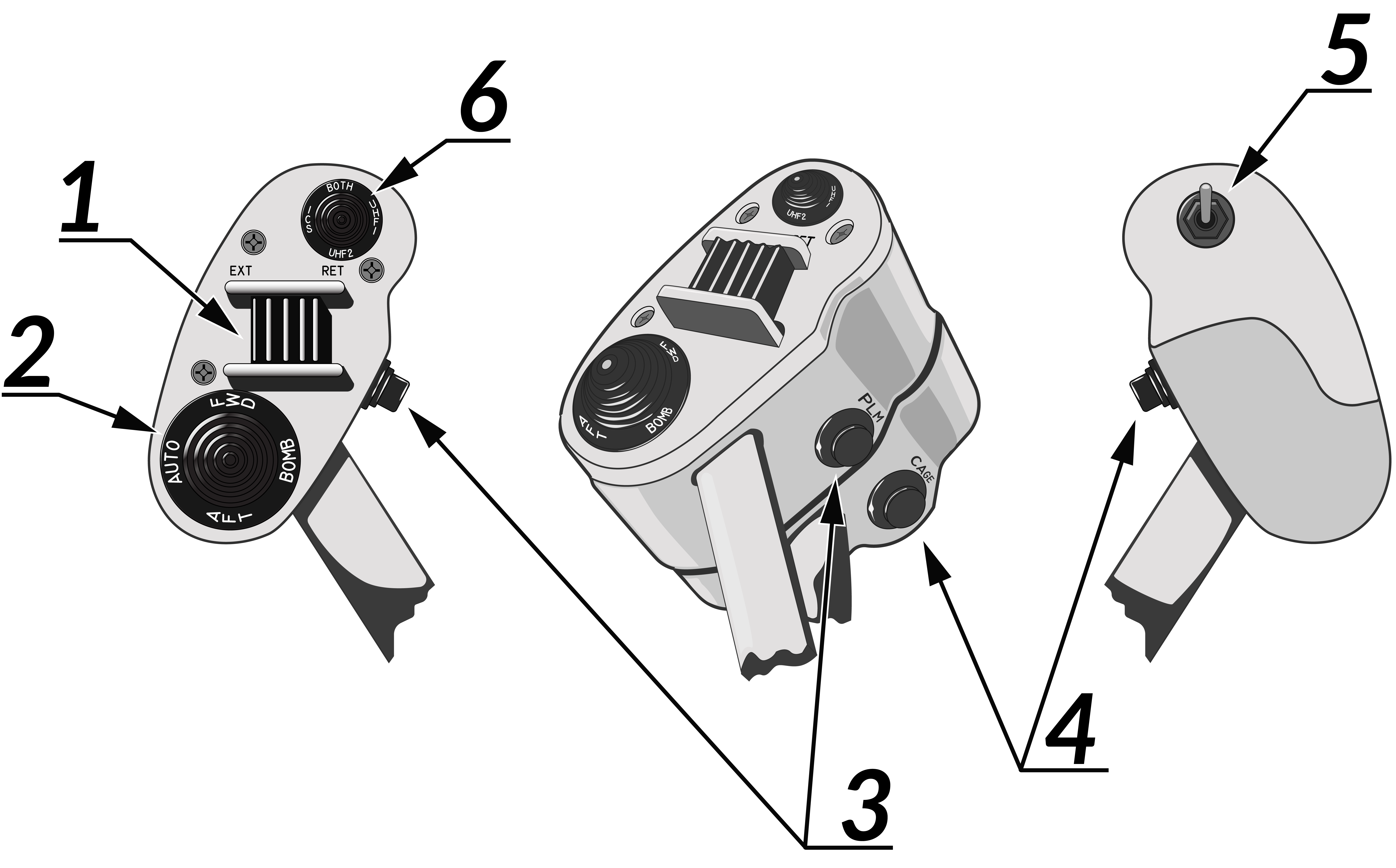 The throttle grips contains various flight controls and HOTAS
functions.
The throttle grips contains various flight controls and HOTAS
functions.
| No. | Control | Function |
|---|---|---|
| 1 | Speed brake switch | Switch controlling extension of the speed brake. |
| 2 | Wing-sweep switch | Switch controlling wing-sweep function. Manual mode only allows positions aft of CADC set position. |
| 3 | PLM button | Button used to command pilot lockon mode of AWG-9. Also used to disengage autopilot while in ACL. |
| 4 | CAGE/SEAM button | Button used to command CAGE/SEAM to AIM-9 initiating lockon. Also used to disengage APC when in use. |
| 5 | Exterior light switch | Switch used to control exterior lights. |
| 6 | ICS PTT switch | Switch allowing pilot to key one or both radios and intercommunication to RIO. |
Throttle Quadrant
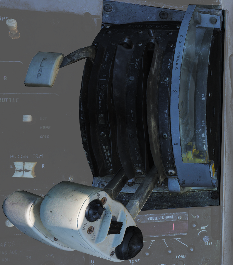
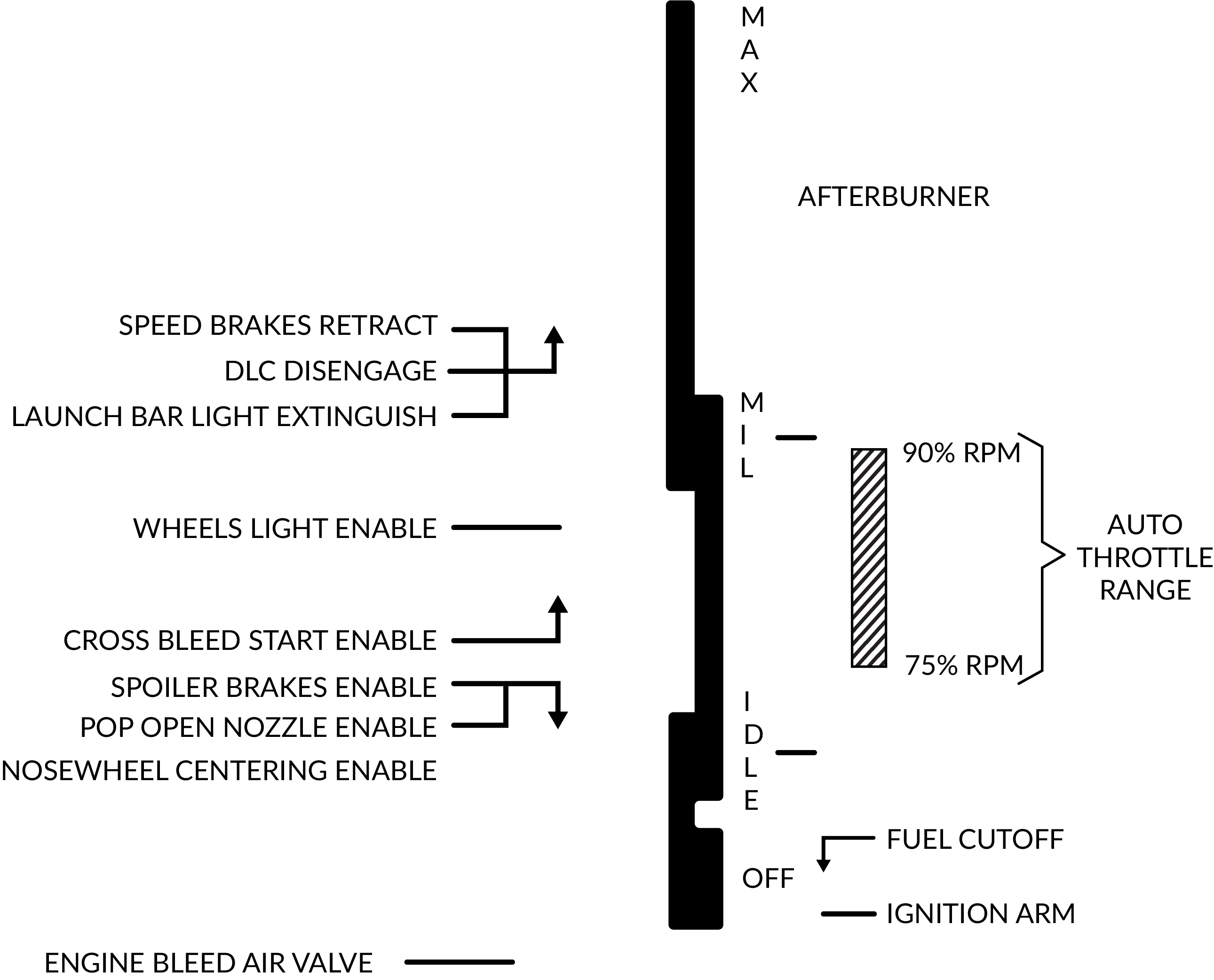 The main
throttle quadrant contains the two main-engine throttle controls, the flap lever and manual
wing-sweep handle in addition to the HOTAS controls on the throttles themselves.
The main
throttle quadrant contains the two main-engine throttle controls, the flap lever and manual
wing-sweep handle in addition to the HOTAS controls on the throttles themselves.
Hydraulic Hand Pump
The hydraulic hand pump is located inboards of the throttle quadrant, near the pilot’s left leg. It is used to manually add hydraulic pressure for brake operation (with gear handle in the down position) or for refueling probe operation in case of a failure in the hydraulic system.
Left Vertical Console
Fuel Management Panel
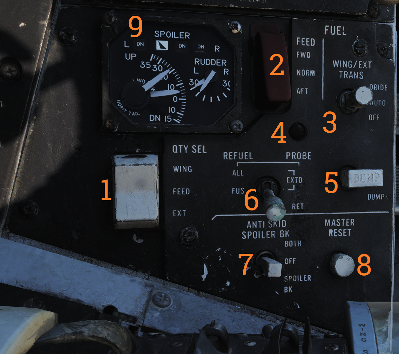
Control panel for various fuel-related systems, CADC master reset, and the anti-skid system.
| No. | Control/Indicator | Function |
|---|---|---|
| 1 | QTY SEL switch | Switch selecting what the fuel quantity tapes on the fuel quantity display shows. Spring-loaded to FEED. FEED - Shows respective feed and fuselage tank fuel quantity. WING - Shows respective wing tank fuel quantity. EXT - Shows respective external fuel tank quantity. |
| 2 | FEED switch | Switch selecting fuel feed to the engines. Guard locks the switch to NORM until lifted. |
| 3 | WING/EXT TRANS switch | Switch selecting operation of the wing and external tanks. ORIDE - Override. AUTO - Normal position. OFF - Turns off fuel feed from the wing and external tanks. |
| 4 | Refueling probe indicator light | Transition light illuminated when refueling probe is not in extended or retracted position. |
| 5 | DUMP switch | OFF/DUMP switch. Allows fuel dump when speed brakes are retracted, afterburner off and weight off wheels. |
| 6 | REFUEL PROBE switch | Selection switch toggling operation of refueling probe. ALL EXTD - All extended, extends refueling probe and allows refueling of all tanks. Also resets WING/EXT TRANS switch to AUTO. FUS EXTD - Fuselage extended, extends refueling probe and allows refueling of only fuselage tanks. RET - Retracted, retracts refueling probe. |
| 7 | ANTI SKID SPOILER BK switch | Selection switch determining operation anti-skid and spoiler brake systems. BOTH - Enables both anti-skid and spoiler brake function with weight on wheels. OFF - Turns off both systems. SPOILER BK - Spoiler brake, enables spoiler brake function with weight on wheels. |
| 8 | MASTER RESET button | Resets CADC failure detection system and associated fault displays. |
Control Surface Position Indicator
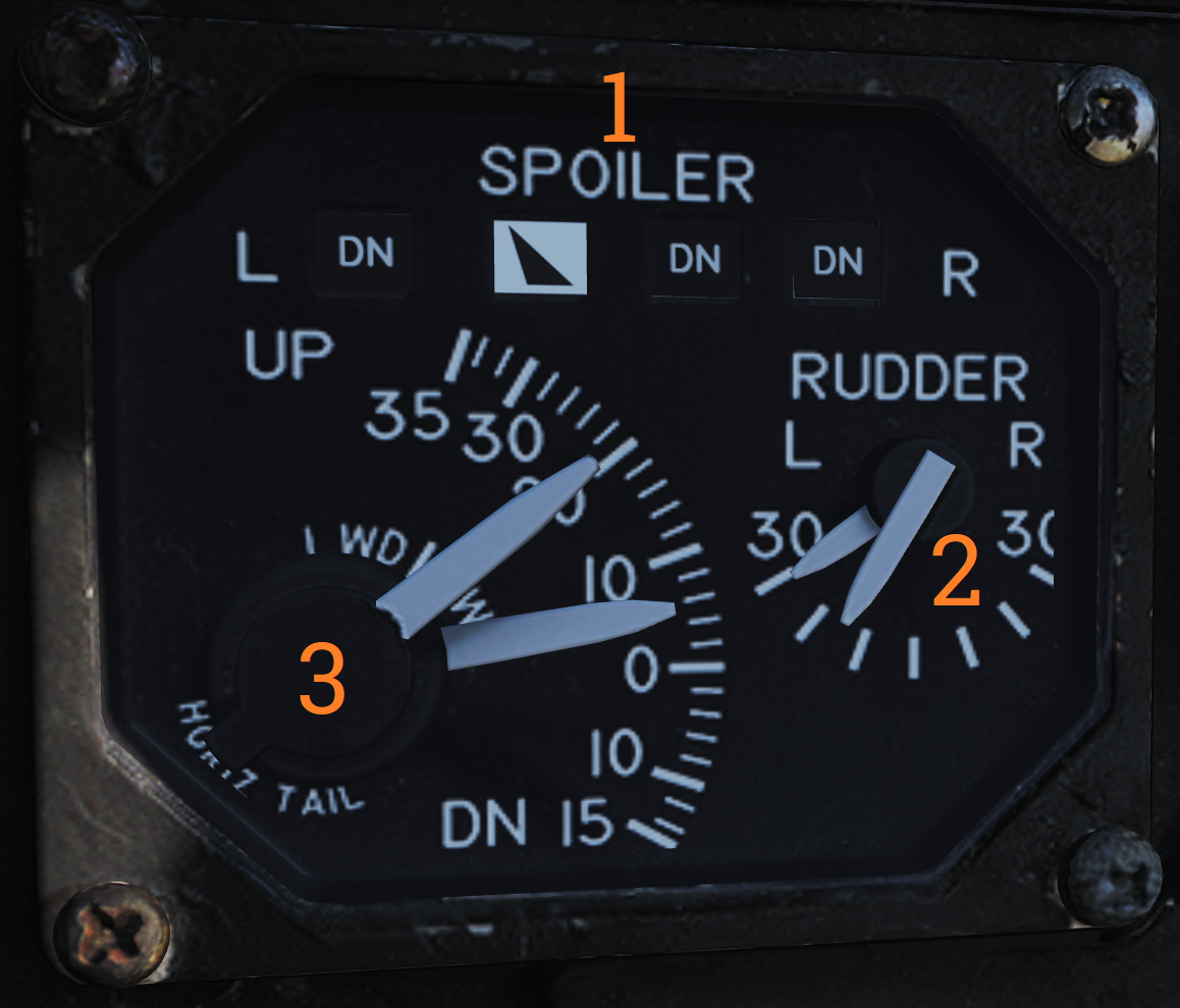
Indicator for indication of control surface positions.
| No. | Indicator | Function |
|---|---|---|
| 1 | SPOILER | Spoiler position indicators. DN - Down, flush with wings. Up-arrow - Extended above wing. Down-arrow - Drooped below wing surface. |
| 2 | RUDDER | Rudder position indicators, shows position of left and right rudders, each marked L or R. |
| 3 | HORIZ TAIL | Horizontal stabilizer position indicators, shows position of left and right stabilizer surfaces, marked L or R respectively. |
Launch Bar Abort Panel
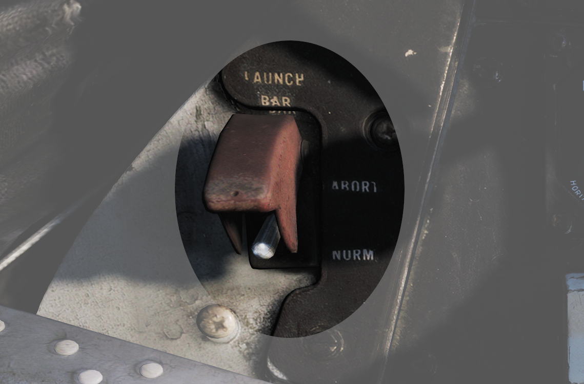
LAUNCH BAR – Selection switch – When held in ABORT lifts the launch bar for launch abortion. Spring-loaded to NORM (Normal) which is the standard position. Not currently used in DCS.
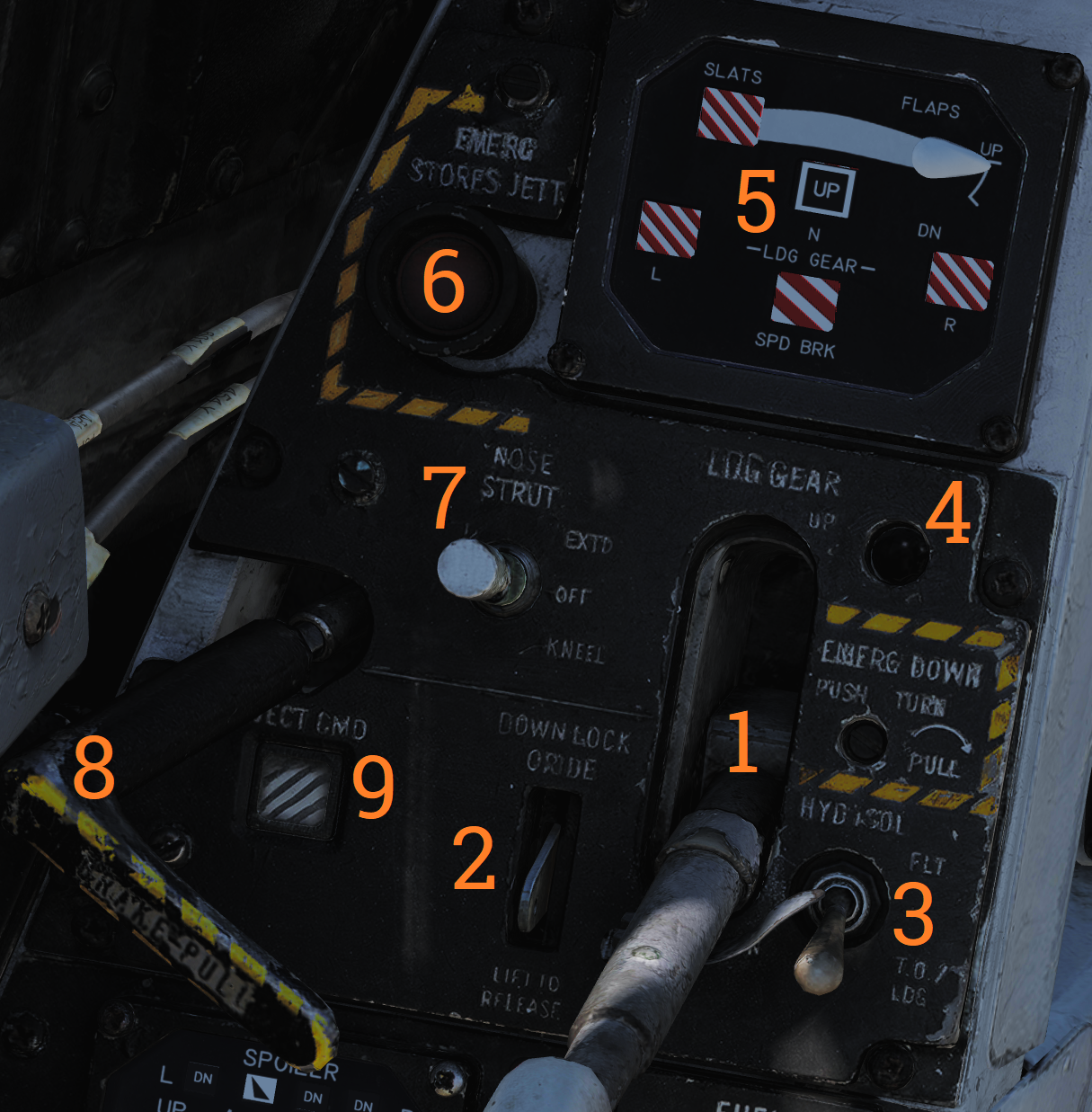
Landing Gear Control Panel
Control panel for the main landing gear and emergency stores jettison.
| No. | Control/Indicator | Function |
|---|---|---|
| 1 | LDG GEAR | Landing gear handle. Selects gear UP or DOWN. For emergency extension in DOWN position, push handle in, turn clockwise and pull out. This releases a compressed nitrogen charge for emergency extension. |
| 2 | DOWN LOCK ORIDE | Indicates weight on wheels when moved down by solenoid. Can be lifted up to override. Non-functional in DCS. |
| 3 | HYD ISOL | Switch isolating landing gear, nosewheel steering and wheel brakes from the combined hydraulic system. Automatically moved to T.O./LDG by LDG GEAR in DOWN position. FLT - In flight operation, isolates systems listed above. T.O./LDG - Take-off/landing, connects systems listed above, allowing them to operate. |
| 4 | Transition light | Illuminates to indicate landing gear position not corresponding to current LDG GEAR handle position. |
| 5 | EMERG STORES button | Emergency stores jettison. Illuminates to indicate activation when pressed. |
| 6 | NOSE STRUT switch | Switch selecting nosewheel strut retraction. EXTD - Extend, extends nosewheel strut and raises and locks launch bar. OFF - Turns off nosewheel strut movement, spring-loaded to this position. KNEEL - Releases pressure from nosewheel strut to retract it, kneeling aircraft. Also unlocks launch bar. |
| 7 | BRAKE-PULL handle | Parking brake, pull out to apply parking brake, push in to release. |
| 8 | EJECT CMD indicator | Indicates ejection system mode for the back seat. PILOT - Pilot ejects both crewmembers, RIO only himself. MCO - Each position ejects both crewmen. |
Wheels and Flaps Position Indicator
Indicates position of flaps and slats, speed brakes, and the landing gear. The slats are indicated as follows:
 | Power off or maneuver slats extended. |
|---|---|
 | Slats extended. |
 | Slats retracted. |
Flap Position is displayed by an indicator moving between UP and DOWN. The first marked section of the indicator indicates maneuver flap-range. The landing gear is indicated as follows:
| Power off or unsafe gear. |
|---|---|
 | Gear down. |
 | Gear retracted and doors closed. |
Speed brakes are indicated as follows:
| Speed brake system power off. |
|---|---|
 | Speed brake partial extension, not in motion. |
 | Speed brake fully extended. |
 | Speed brake retracted. |
Left Knee Panel
Hydraulic Pressure Indicator
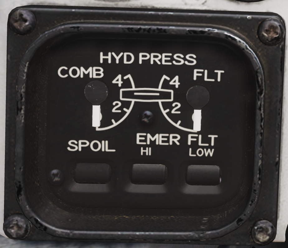
Shows hydraulic pressure of the combined and flight hydraulic systems. The SPOIL (Spoiler) ON/OFF-flag indicates pressurization of the outboard spoiler module. EMER FLT HI ON/OFF-flags indicate backup flight hydraulic system pressures when HI or LOW is selected respectively.
Oil Pressure Indicator
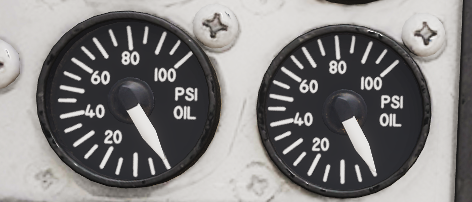
Displays oil pressure for each engine. Range is 0 - 100 psi, normal range is 25 - 65 psi, varying with engine rpm.
Exhaust Nozzle Position Indicator

Displays position of engine nozzles. Range 0 – 5 with 5 being fully open.
Electronic Instrument Group
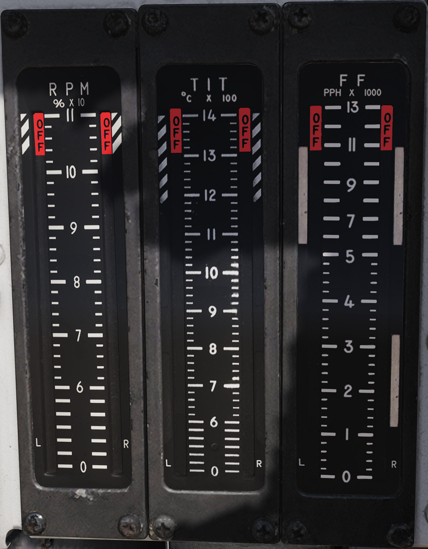
Displays engine RPM (High-pressure compressor rotor speed (N2)), EGT (Exhaust Gas Temperature) and FF (Fuel Flow) for respective engine.
💡 Note: Image shows TF-30 engine instruments, F110 EIG image coming soon.
💡 Note 2: FF is not indicated for the additional fuel used in afterburner.
Left Instrument Panel
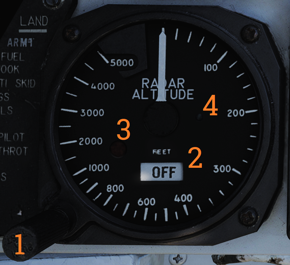
Radar Altimeter
 Control and indicator for the radar altimeter.
| No. | Control/Indicator | Function |
|---|---|---|
| 1 | Radar altimeter control knob | Fully counterclockwise position turns the altimeter off. Rotation clockwise sets the altitude warning level, increasing clockwise. Depressing the knob starts the altimeter BIT. |
| 2 | OFF flag | Shown if the system is off, power is off, or the system loses ground lock. |
| 3 | Low altitude warning light | Red light illuminated when below set altitude warning level. |
| 4 | Self-test light | Green light that should illuminate when the altimeter BIT is run. The readout should also display 100 feet +/- 10. |
| 5 | Low-altitude limit index | Small triangular bug moving along the outer edge, displays set altitude warning level. |
Note: Radio override does not disable the low-altitude warning tone.
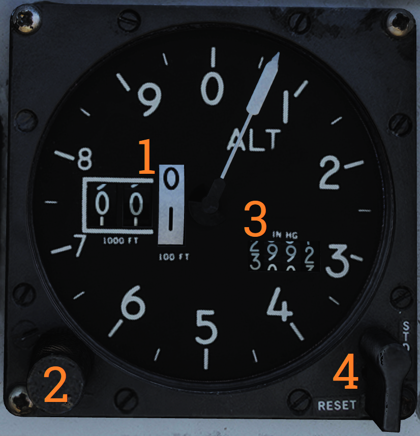
Servopneumatic Altimeter
 Control and indicator for the servopneumatic altimeter.
| No. | Control/Indicator | Function |
|---|---|---|
| 1 | Altimeter readout | Displays altitude digitally on three drums showing 10,000, 1,000, and 100 feet respectively. It also displays altitude on a pointer on a circular scale indicating 100’s of feet. |
| 2 | Baroset knob | Sets local pressure in inches of mercury (in.Hg). Only used locally on the altimeter readout, all other digital indicators (via CADC) use a set 29.92 in.Hg value. |
| 3 | Local barometric pressure | Indicates barometric pressure setting, also called the Kollsman Window. |
| 4 | Mode switch | Three-position switch, spring-loaded to return from RESET. If power and altitude data from CADC is present, switch can be held in RESET for 3 seconds to allow normal (servoed) mode of operation. If set to STBY or power or CADC data is absent for more than 3 seconds, the system switches to backup (pressure) mode. |
| 5 | STBY flag | Red flag reading STBY that appears if the system is in backup (stand-by) mode. |
Note: At high speeds and below 10,000 feet, due to pressure changes, errors in readout up to as much as 1,200 feet when transonic and up to as much as 4,000 feet when supersonic can occur.
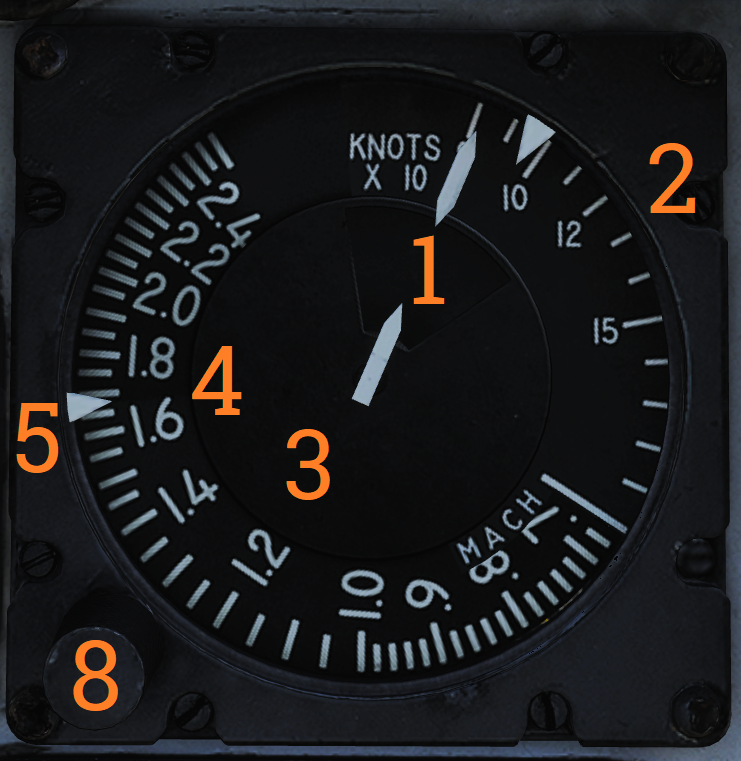
Airspeed Mach Indicator
 Indicated airspeed and Mach number display.
| No. | Control/Indicator | Function |
|---|---|---|
| 1 | Airspeed dial | Shows indicated airspeed on three scales, two for indicated airspeed and one moving for Mach number. |
| 2 | Indicated airspeed scale (outer) | Readout for indicated airspeed up to 200 knots. |
| 3 | Indicated airspeed scale (inner) | Readout for indicated airspeed from 200 knots to 850 knots. Covered by airspeed dial until relevant. |
| 4 | Mach number scale | Readout for Mach number. Moved to show correct Mach number relative to indicated airspeed. |
| 5 | Indicated airspeed index pointer | Can be set to desired indicated airspeed. |
| 6 | Mach number index pointer | Can be set to desired Mach number. Not visible in image. |
| 7 | Safe Mach number index pointer | Shows safe Mach number calculated by the CADC. Not visible in image. |
| 8 | Index knob | Knob with a pull-out and push-in position. One sets the indexer for indicated airspeed and the other for Mach number. |
Vertical Velocity Indicator
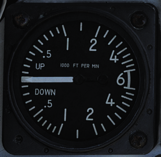 Shows vertical velocity in thousands of feet. Can show erroneous readings if sudden or abrupt changes of attitude occur because of the changing airflow over the static probe.
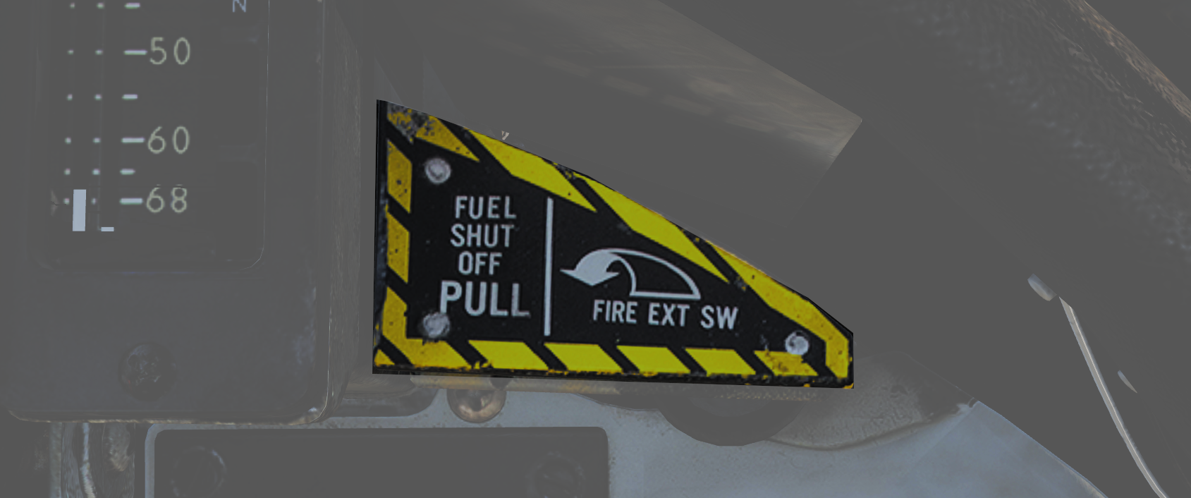
Left Engine Fuel Shutoff Handle
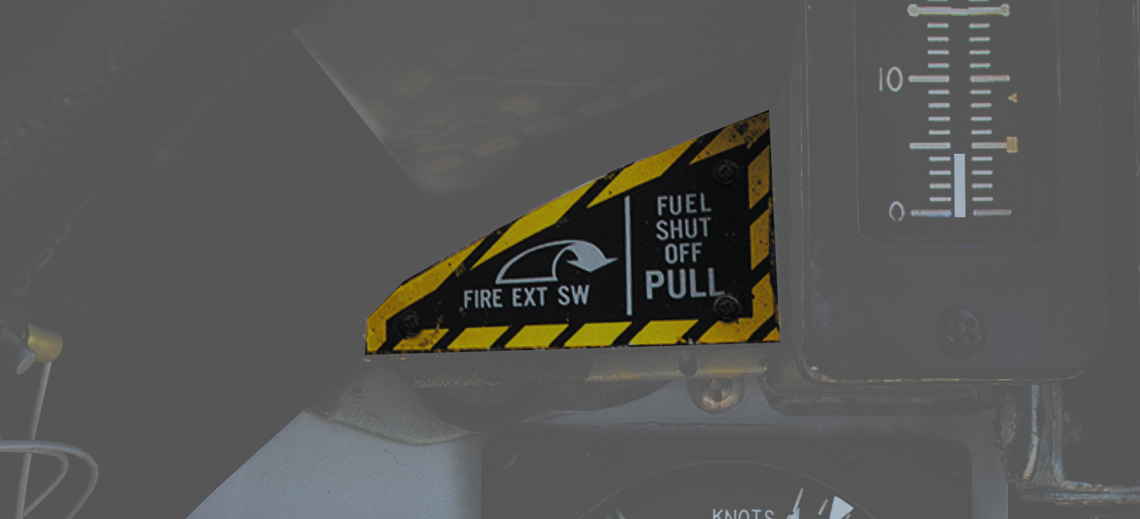 Pull to shut off fuel to the left engine in case of emergency. Push in to re-enable fuel flow to the engine. Should not be used to secure the engine.
Left engine fire extinguishing button is located behind the handle, accessible when the handle is pulled out.
Angle-of-Attack Indicator
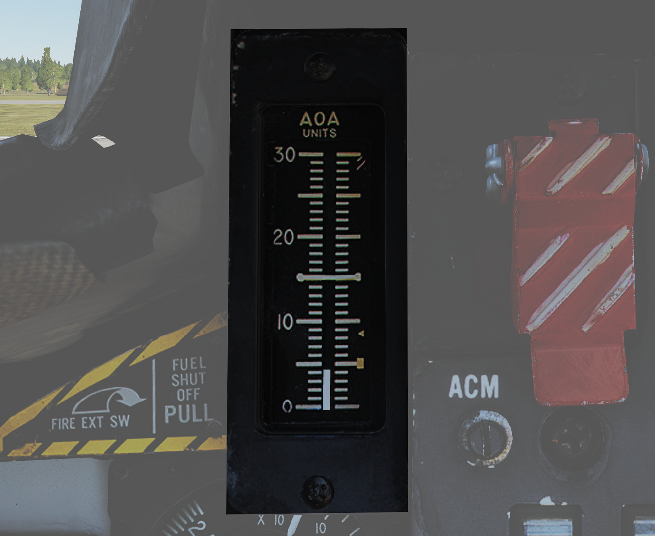 Tape indicating angle of attack (AOA) on a scale of 0 to 30 units. (Equivalent to -10° to +40° rotation of the AoA probe.)
The indicator has markers on the right for climb (5), cruise (8.5), and stall (29), and a reference bar for on-speed approach (15).
Left Windshield Frame
Approach Indexer
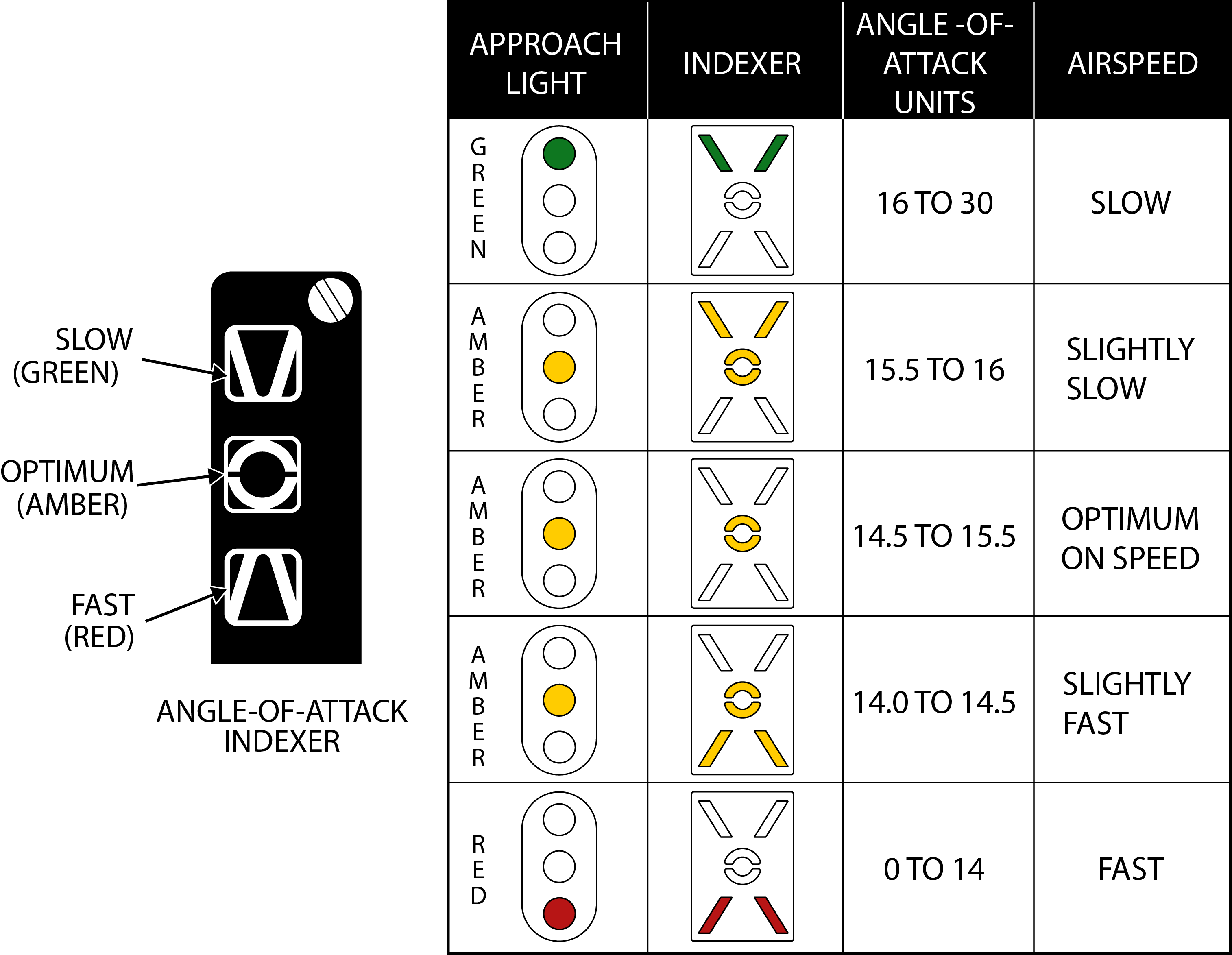 Contains three lights showing angle-of-attack (AOA) relative to on-speed AOA.
Green being too slow, amber being on-speed AOA, and red being too fast.
If the HOOK BY-PASS switch is set to CARRIER, the lights will flash if the arresting hook is up while the landing gear is down.
These lights are repeated on the approach lights on the nosewheel strut, allowing the LSO to see aircraft AOA during carrier landings.
Wheels Warning/Brakes Warnings/ACLS/AP Caution/NWS Engage Caution/Auto Throttle Caution Lights
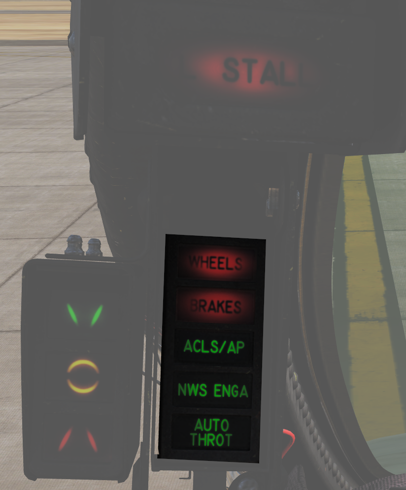 HUD left side indicators.
| No. | Indicator | Function |
|---|---|---|
| 1 | WHEELS | Warning light flashes with landing gear not down and locked, flaps below 10°, and either throttle below 85%. |
| 2 | BRAKES | Warning light indicating antiskid or brake failure. Also lights when parking brake is set. |
| 3 | ACLS/AP | Caution light indicating that ACLS or autopilot is disengaged. |
| 4 | NWS ENGA | Caution light indicating nosewheel steering (NWS) is engaged. |
| 5 | AUTO THROT | Caution light indicating disengagement of the automatic throttle control mode not resulting from the throttle mode switch. |
Center Panel
Heads-Up Display
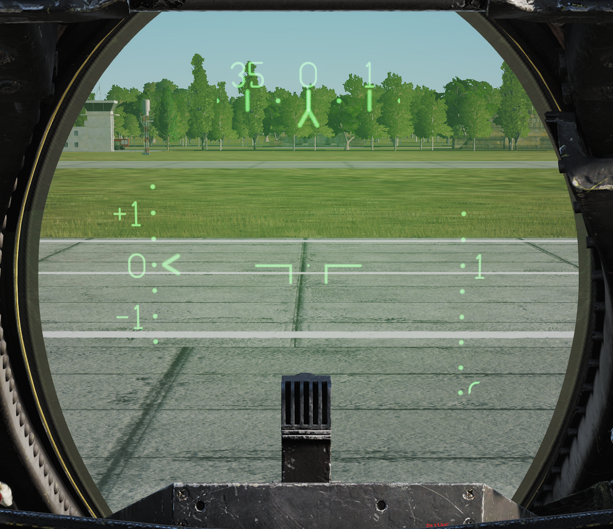 Projects flight and weapons data onto the forward section of the canopy/windscreen. Night mode can be selected using the control on the right side of the VDI.
Has two engine stall warning lights (L STALL & R STALL) mounted on the left and right sides, respectively. They indicate the presence of an engine stall condition in their respective engine.
Note: For more information see relevant chapters under Navigation and Weapons and Weapons Employment Overview.
Cockpit Television Sensor (CTVS)
 The cockpit television sensor (CTVS) records the HUD for registration of weapons delivery.
Note: Not implemented in DCS.
Air Combat Maneuver Panel
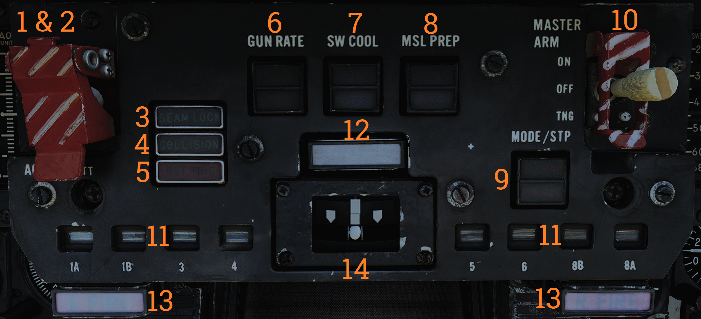 Main pilot armament control panel.
| No. | Control/Indicator | Function |
|---|---|---|
| 1 | ACM switch/cover | Lifting the ACM (Air combat maneuver) cover activates the ACM mode and allows access to the ACM jettison button. |
| 2 | ACM JETT button | Button under the ACM cover that enables jettison of stores selected on the RIO’s ARMAMENT panel. Will not jettison Sidewinders regardless if selected. |
| 3 | SEAM LOCK light | Light that illuminates to show that Sidewinder acquisition is in progress while in slaved and boresight SEAM modes. Lights up during the 4.5 second SEAM acquisition attempt and remains lit thereafter if the seeker has locked onto a target. |
| 4 | COLLISION light | Light that illuminates to show that collision steering has been selected during AWG-9 STT operation. |
| 5 | HOT TRIG light | Red light that indicates that the HOT TRIGGER conditions are met. When this is lit, the trigger will release a weapon. |
| 6 | GUN RATE switch | Toggle switch with light indication of selected option. HIGH - Selects gun rate of 6,000 rounds per minute. Normally for A/A operation. LOW - Selects gun rate of 4,000 rounds per minute. Normally for A/G operation. Automatically set to HIGH when ACM mode is selected. |
| 7 | SW COOL switch | Toggle switch with light indication of selected option. Manual control of Sidewinder seeker cooling. Automatically set to ON when ACM mode is selected. |
| 8 | MSL PREP switch | Toggle switch with light indication of selected option. Commands WCS to prepare AIM-54 and AIM-7 missiles. Automatically set to ON when ACM mode is commanded. |
| 9 | MSL MODE switch | Toggle switch with light indication of selected option. Selects NORM (normal) or BRSIT (boresight) operation for missile launch. Controlled by WCS when in ACM mode. |
| 10 | MASTER ARM switch | Enables weapons release and selective and auxiliary jettison. OFF - Disables electrical power to release circuitry. ON - Enables electrical power to release circuitry. Position locked until the master arm cover is lifted. TNG (training) - Enables the in-flight training mode. |
| 11 | Station status flags | Shows indication of weapon status for the different stations. BLACK - Station not loaded or weapon not ready. WHITE - Station and weapon ready. CHECKERBOARD - Weapon is selected and ready for launch. On the ground indicates that fuselage rails are up and locked and that loaded weapons are armed. |
| 12 | MASTER CAUTION light and button | Flashes to indicate status change on the pilot caution/advisory panel. Press to reset and turn off light until the next event. |
| 13 | L FIRE and R FIRE lights | Engine fire warning lights. Illuminates when a fire has been detected in the respective engine. |
| 14 | Turn-and-Slip indicator | Indicator showing rate of turn around the aircraft vertical axis. The upper part contains an electrically driven pointer, one needle deflection equaling a 360° turn in 4 minutes. The lower part contains an inclinometer with a ball suspended in a dampening fluid. |
Vertical Display Indicator (VDI)
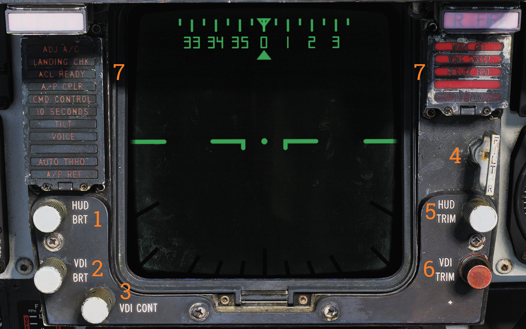 Display that complements the HUD in displaying flight and weapons data.
| No. | Control/Indicator | Function |
|---|---|---|
| 1 | HUD BRT control | Controls HUD brightness. |
| 2 | VDI BRT control | Controls VDI brightness. |
| 3 | VDI CONT control | Controls VDI contrast. |
| 4 | FILTER handle | When pulled inserts filter for HUD night operation. |
| 5 | HUD TRIM control | Allows adjustment/trim of pitch lines on HUD. |
| 6 | VDI TRIM control | Allows adjustment/trim of pitch lines on VDI. |
| 7 | VDI caution lights | VDI-mounted caution lights. See images and tables below. |
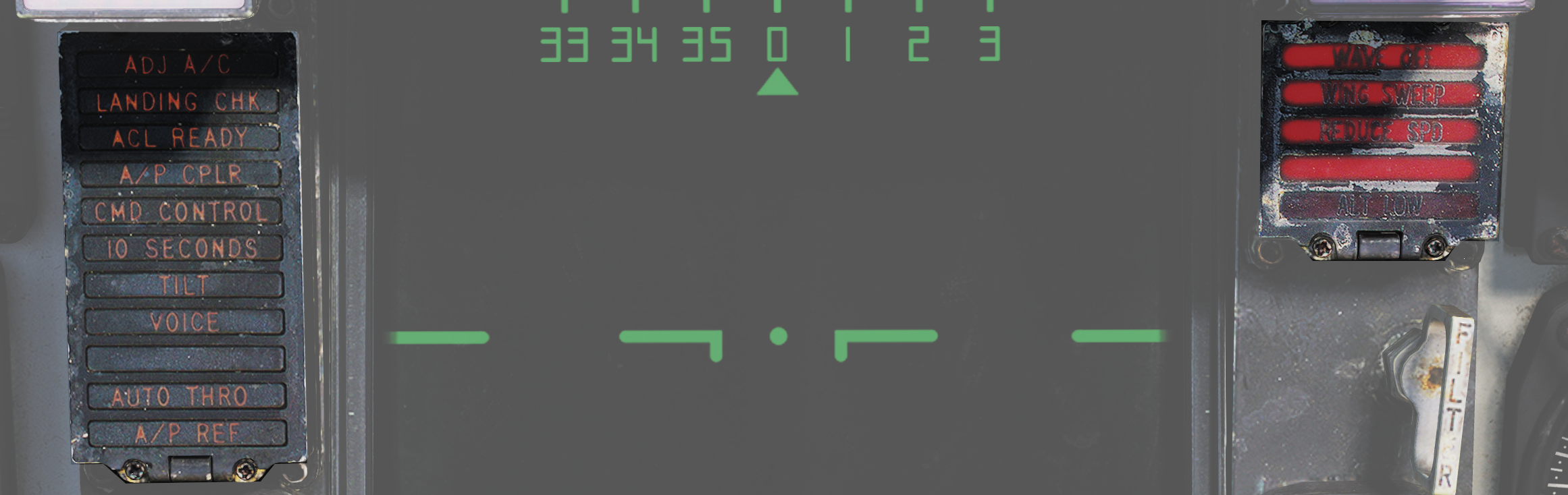 Data link warning and caution lights situated at the VDI panel.
| No. | Indicator | Function |
|---|---|---|
| 1 | ADJ A/C | Advisory light indicating other aircraft close to own traffic pattern. |
| 2 | LANDING CHK | Advisory light indicating carrier has a channel ready for ACL and that the crew should prepare for carrier landing. |
| 3 | ACL READY | Warning light indicating CATCC has acquired the aircraft and is transmitting glidepath information to the aircraft. |
| 4 | A/P CPLR | Warning light indicating CATCC is ready to control the aircraft. |
| 5 | CMD CONTROL | Warning light indicating the aircraft is under data link control for landing. |
| 6 | 10 SECONDS | Warning light indicating that carrier motion is added to data link info and commands during landing. Indicates 10 seconds to arrival at the next point in approach pattern in other modes. |
| 7 | TILT | Warning light indicating no data link command received for the last 2 seconds during ACL. When not in ACL, it indicates no data link messages during the last 10 seconds. |
| 8 | VOICE | Warning light indicating CATCC not ready for ACL, switch to standard voice procedures. |
| 9 | A/P REF | Warning light indicating autopilot selected but not engaged. Exception: altitude and heading hold. |
| 10 | WAVEOFF | Warning light indicating waveoff commanded. |
| 11 | WING SWEEP | Warning light indicating failure in both wing-sweep channels or disengagement of spider detent. |
| 12 | REDUCE SPEED | Warning light indicating flap retraction failure with greater than 225 knots indicated airspeed. Also indicates safe Mach number exceeded. |
| 13 | ALT LOW | Non-functional, light on radar altimeter is used instead. |
Horizontal Situation Display Indicator (HSD)
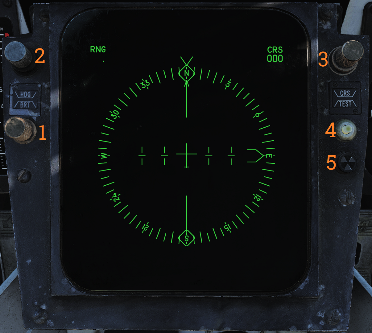 The horizontal situation display is used to display navigational information to the pilot. It can also be used to repeat the RIO’s TID to the pilot.
| No. | Control/Indicator | Function |
|---|---|---|
| 1 | BRT control | Controls HSD brightness. |
| 2 | HDG control | Controls heading reference bug in TACAN mode. |
| 3 | CRS control | Controls desired course in MAN (manual) and TACAN mode. |
| 4 | TEST button | Allows reset of the HSD to re-enable display if the overload protection is tripped. Also displays the HSD IR field test display on the HSD. |
| 5 | BIT indicator | Indicates failure in HSD by showing white flags. Reset by rotating it clockwise. |
Note: For more information see relevant chapters under Navigation and for the TID repeat Tactical Information Display (TID) and Associated Controls.
Cabin Pressure Altimeter
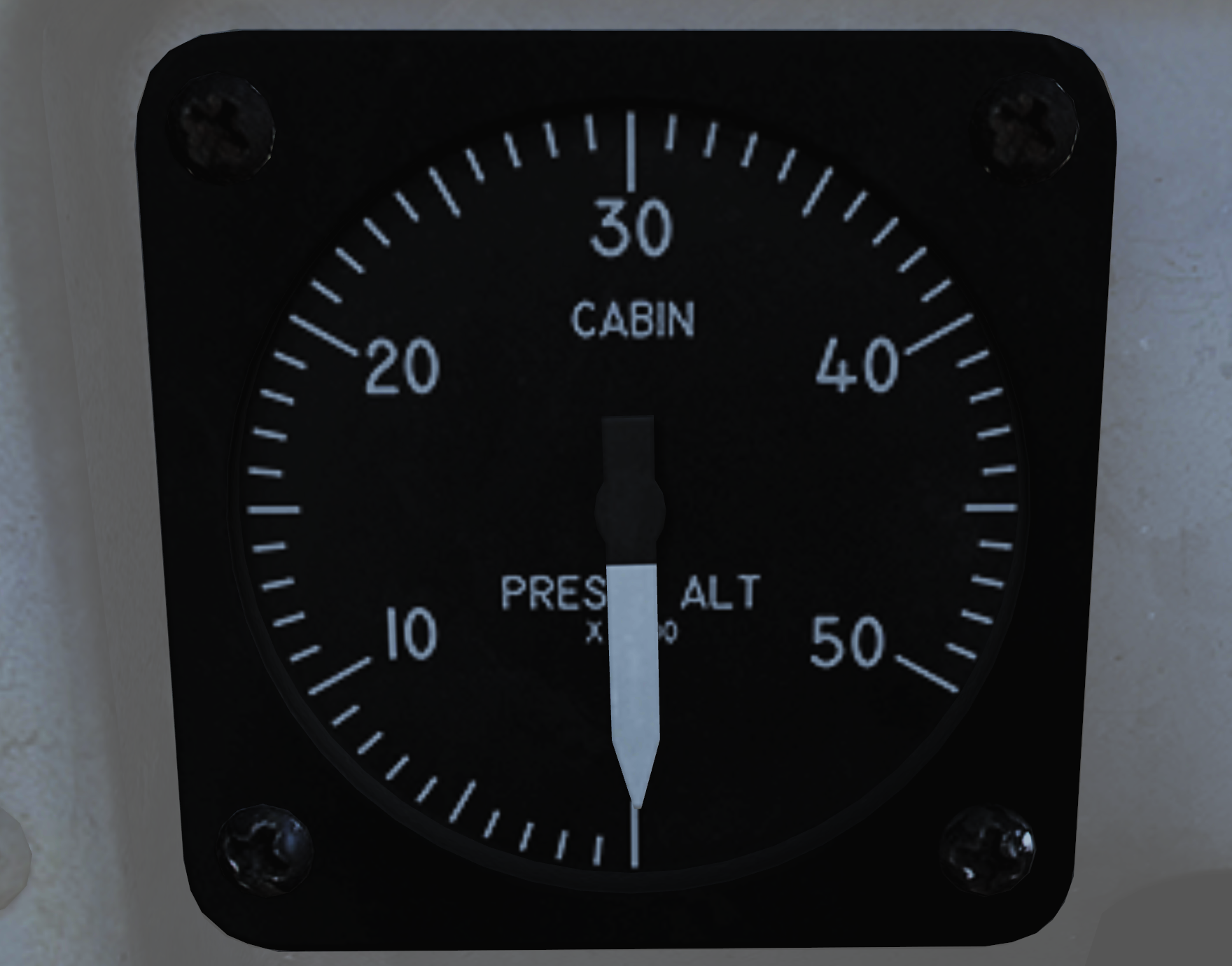 Displays cabin pressure in 1,000-foot increments from 0 to 50,000 feet.
Emergency Brake Pressure Indicator
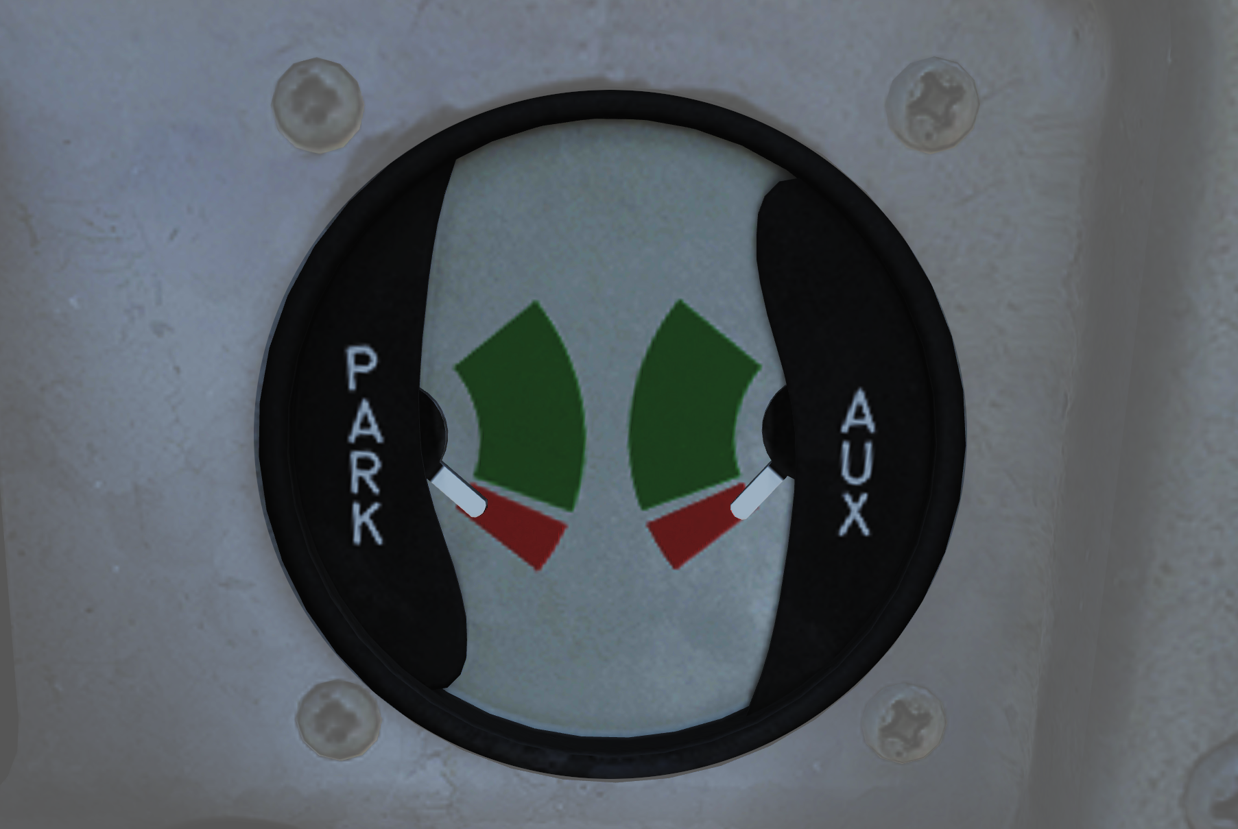 Displays hydraulic pressure available from the emergency brake accumulators to the auxiliary and parking wheel brake systems.
| No. | Indicator | Function |
|---|---|---|
| 1 | PARK | Shows brake pressure available for parking brakes. Green segment indicates 2,150 to 3,000 psi, red indicates 1,900 to 2,150 psi. When green there is pressure enough for approximately 3 applications. |
| 2 | AUX | Shows brake pressure in the auxiliary brake pressure which can be used via the toe brakes on the pedals. Green segment indicates 2,150 to 3,000 psi (approximately 13 to 14 applications) while red indicates 1,900 to 2,150 psi (approximately 5 applications). |
Control Stick
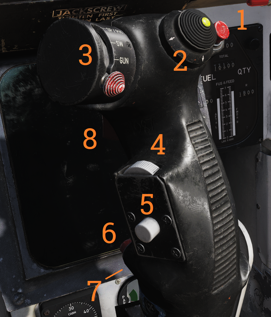 Used to control aircraft roll and pitch. Also various other functions according to table below.
| No. | Control | Function |
|---|---|---|
| 1 | Bomb release button | Stores release button, used for air-to-ground ordnance (except rockets) and loaded external countermeasures. |
| 2 | Pitch and roll trim hat | Hat used to control trim, up/down trims pitch and left/right trims roll. |
| 3 | Weapon select hat | Selector hat moveable up and down and depressable. SP or PH - Selects AIM-7 or AIM-54, depression toggles between types. SW - Selects AIM-9, depression toggles between stations. GUN - Selects M-61A1 Vulcan gun. OFF - Inhibits weapon release. |
| 4 | DLC & maneuver flap command wheel | Thumbwheel used to control DLC or maneuver flaps. With DLC engaged forward rotation extends spoilers and aft rotation retracts spoilers. With flaps up and DLC disengaged forward rotation retracts maneuvering flaps/slats and aft rotation extends them. The logic behind the function being that pulling the wheel towards you increases lift and pushing it away decreases lift. |
| 5 | DLC engage/disengage & countermeasure dispense button | Momentary depression with flaps down, throttles less than MIL and no spoiler system failure engages DLC. With flaps up button sends command to ALE-39 to dispense chaff or flares according to RIO setting. DLC is disengaged by further momentary depression of the button, raising flaps, or advancing either throttle to MIL. |
| 6 | Autopilot reference & nosewheel steering button | Button toggling nosewheel steering with weight on wheels. Without weight on wheels is used to engage enabled autopilot modes. |
| 7 | Autopilot emergency disengage paddle | Disengages all autopilot modes and DLC and releases all autopilot switches and roll and pitch SAS switches to OFF position. With weight on wheels additionally reverts throttle mode to MAN (manual) while depressed. |
| 8 | Weapon firing trigger | Two-stage trigger. First detent enables CTVS and gun camera. Second detent releases selected forwards firing weapon. |
Note: CTVS not implemented in DCS.
Right Windshield Frame
ECM Warning Lights
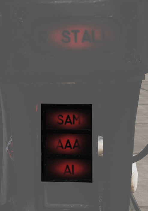
Warning lights connected to the ALR-67 indicating different types of threats.
| Indicator | Function |
|---|---|
| SAM | Steady illumination when detecting lock-on from a SAM tracking radar. Flashes when missile launch is detected. |
| AAA | Steady illumination when detecting lock-on from a AAA tracking radar. Flashes when AAA firing is detected. |
| AI | Steady illumination when detecting lock-on from an airborne interceptor radar. |
Standby Compass
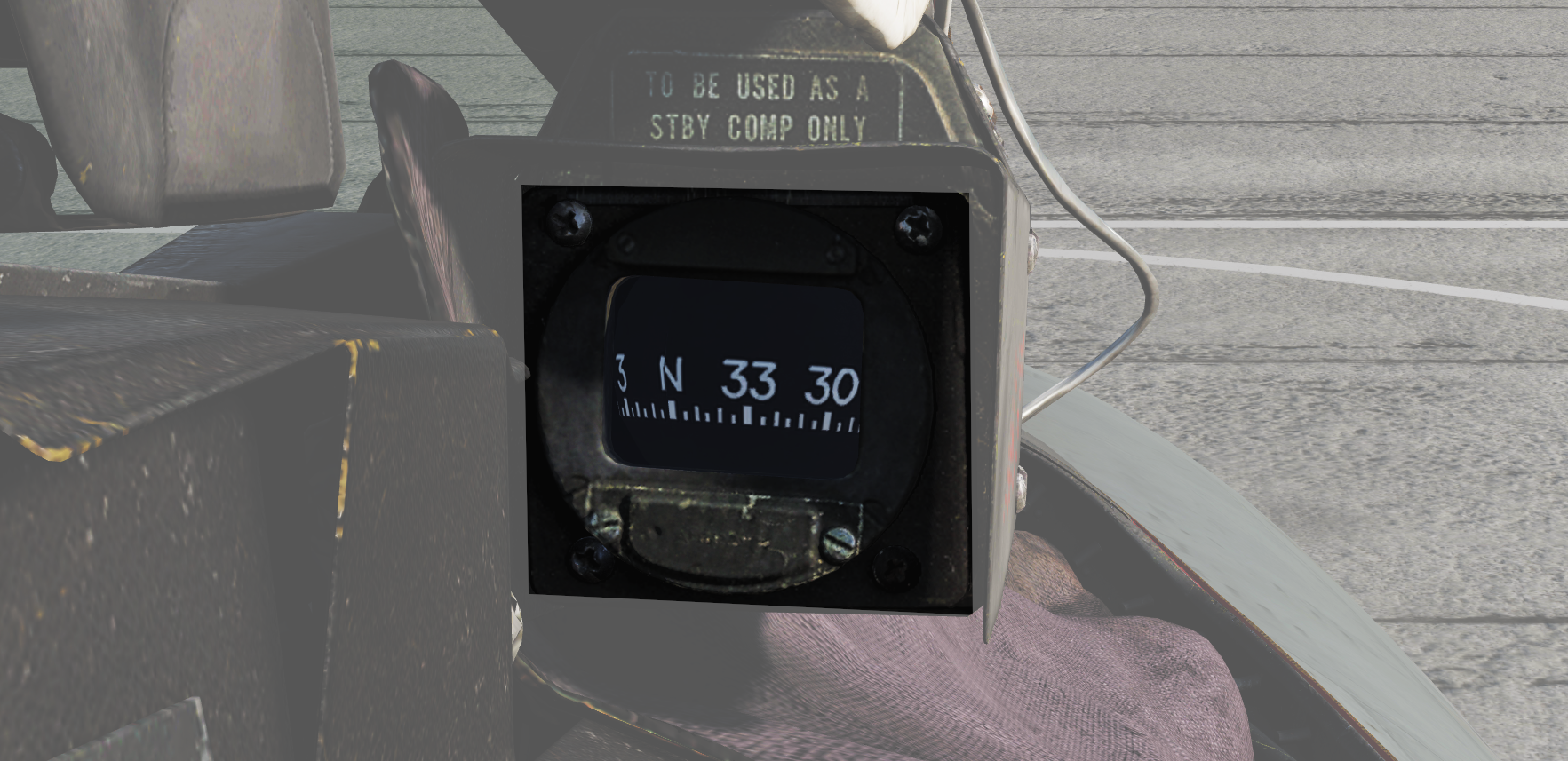
Conventional standby compass.
Right Instrument Panel
Wing-Sweep Indicator
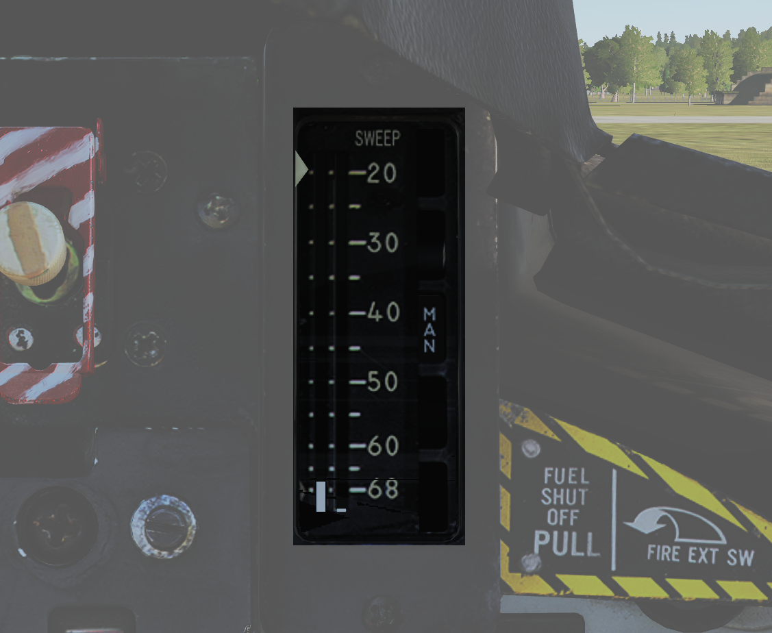 Indicator detailing the status of the wing-sweep system.
| No. | Indicator | Function |
|---|---|---|
| 1 | Leftmost indicator pointer | Shows wing-sweep program position which is also the max forward angle at present airspeed and altitude. |
| 2 | Middle tape | Shows commanded wing-sweep position. |
| 3 | Rightmost tape | Shows actual wing-sweep position. |
| 4 | Indicator windows | The five indicator windows show the current operating mode. |
Right Engine Fuel Shutoff Handle
 Pull to shut off fuel to the right engine in case of emergency. Push in to re-enable fuel flow to the engine. Should not be used to secure the engine.
Right engine fire extinguishing button is located behind the handle, accessible when the handle is pulled out.
Standby Attitude Indicator
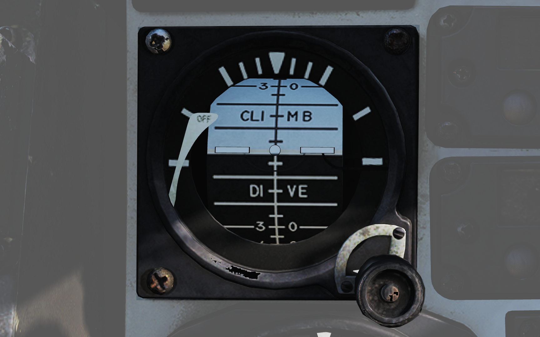 Standalone standby attitude indicator.
| No. | Indicator/Control | Function |
|---|---|---|
| 1 | OFF flag | Visible on the left side when caged or when unpowered. |
| 2 | Knob | Cages/uncages the indicator and allows trim to correct pitch. In pulled-out position the indicator is caged. When pushed in, uncages the indicator and allows pitch trim by turning the knob. |
UHF/VHF Remote Indicators
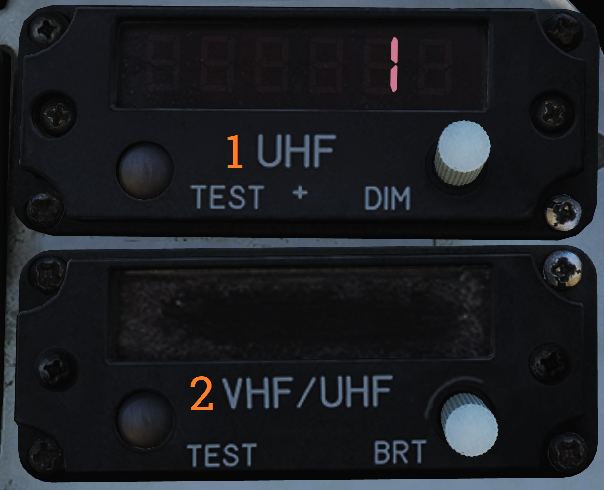 Remote indicators displaying set frequency or channel of UHF 1 (AN/ARC-159) and V/UHF 2 (AN/ARC-182).
| No. | Control/Indicator | Function |
|---|---|---|
| 1 | UHF 1 remote channel/frequency indicator (pilot) | Displays a readout of the frequency or channel set for the UHF 1 radio. TEST - Initiates test for the indicator, no fault resulting in 888.888 readout. DIM - Controls display brightness. |
| 2 | V/UHF 2 remote channel/frequency indicator (pilot) | Displays a readout of the frequency or channel set for the V/UHF 2 radio. TEST - Initiates test for the indicator, no fault resulting in 888.888 readout. BRT - Controls display brightness. |
Bearing Distance Heading Indicator (BDHI)
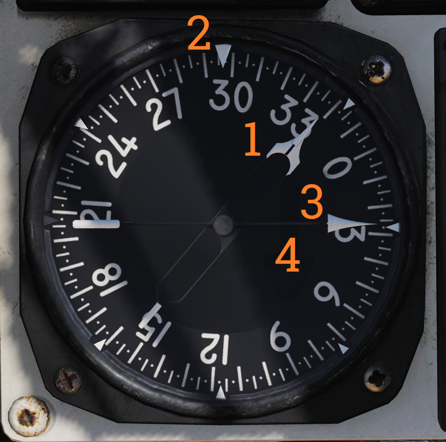 Display indicating azimuth and bearing information.
| No. | Indicator | Function |
|---|---|---|
| 1 | No. 2 bearing pointer | Indicates magnetic course to tuned TACAN station. |
| 2 | Compass rose | Shows current aircraft magnetic heading. |
| 3 | No. 1 bearing pointer | Indicates bearing to tuned UHF/ADF station. |
| 4 | Distance counter | Indicates slant range to tuned TACAN station in nautical miles. (Not visible in this image.) |
ALR-67 Indicator
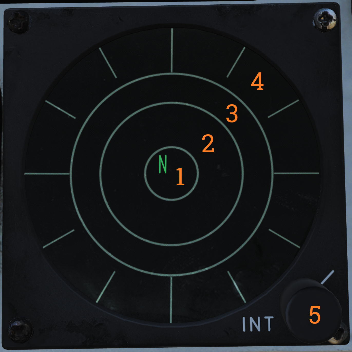 Indicator showing emitters detected by the ALR-67 RWR (radar warning receiver) set.
| No. | Control/Indicator | Function |
|---|---|---|
| 1 | System status circle, area I | Upper left quadrant of 1. Shows symbol indicating type of threats selected to be shown. |
| 2 | System status circle, area II | Upper right quadrant of 1. Indicates if limited mode is selected. |
| 3 | System status circle, area III | Lower half of 1. Displays failure codes and if offset display is selected. |
| 4 | Non-lethal band | Displays emitters not a direct threat to own aircraft, either because deemed out of range or lacking weaponry. |
| 5 | Lethal band | Displays threats that are deemed within range and capable of engaging own aircraft but not currently doing so. |
| 6 | Critical band | Displays direct threats to own aircraft. Systems capable of engaging own aircraft and showing current intent of doing so. |
| 7 | INT knob | Intensity/brightness knob. Controls the brightness of the display. |
Canopy Jettison Handle
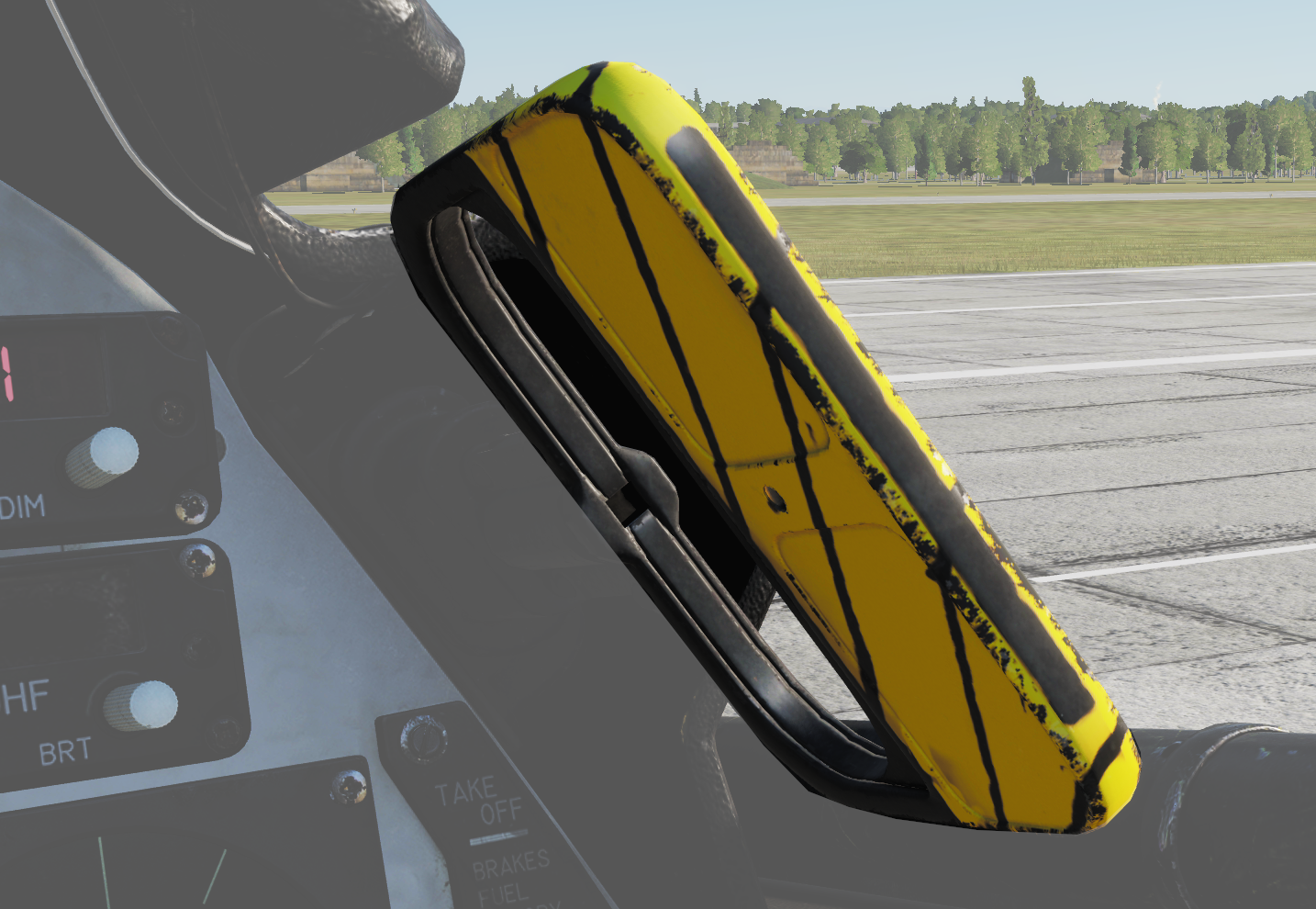 Used to jettison canopy manually.
Right Knee Panel
Fuel Quantity Indicator
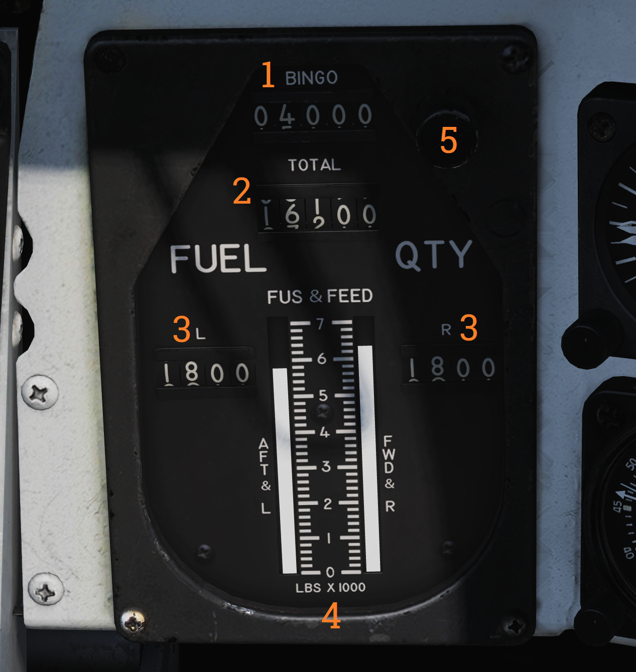 Shows fuel quantity in the different aircraft tanks.
| No. | Control/Indicator | Function |
|---|---|---|
| 1 | BINGO readout | Shows currently set BINGO fuel quantity. |
| 2 | TOTAL counter | Total fuel quantity readout, shows totalled fuel quantity in all aircraft tanks. |
| 3 | L & R counters | Shows fuel quantity in currently selected respective (L or R) tanks (feed, wing, or ext) set by the QTY SEL switch on the fuel management panel. |
| 4 | FUS & FEED tapes | Shows fuel quantity in respective fuselage tanks. Left tape indicates left feed and aft fuselage tanks. Right tape indicates right feed and forward fuselage tanks. |
| 5 | SET knob | Knob used to set BINGO fuel quantity. Turn to set desired quantity. |
Accelerometer
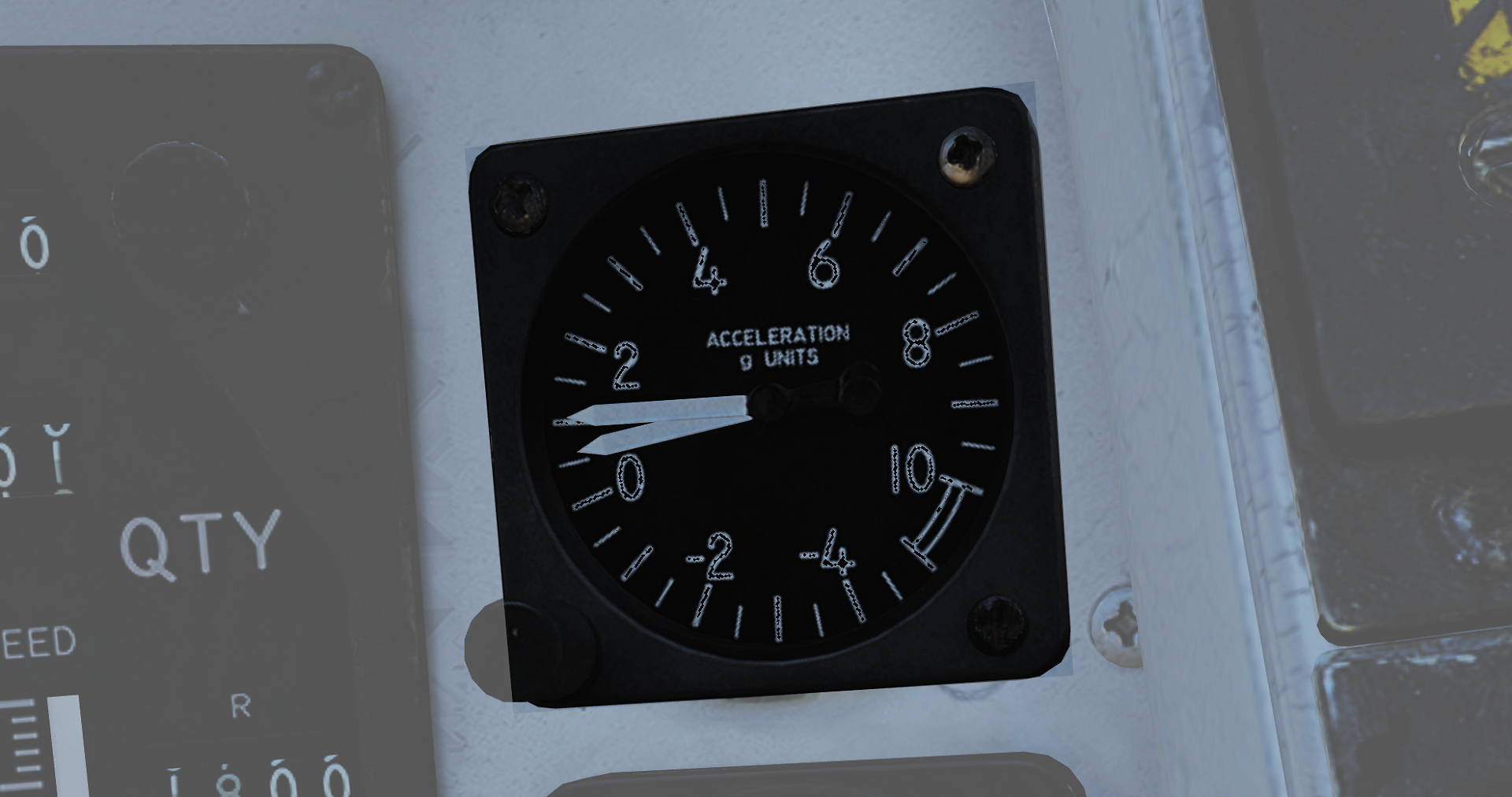 Instrument showing current aircraft g-load (acceleration along the aircraft vertical axis). It’s graded in g from -5g to +10g. One pointer will show current g-load while the other two will indicate max reached negative and positive g-load. These can be reset by pushing the PUSH TO SET button on the lower left corner of the instrument.
Clock
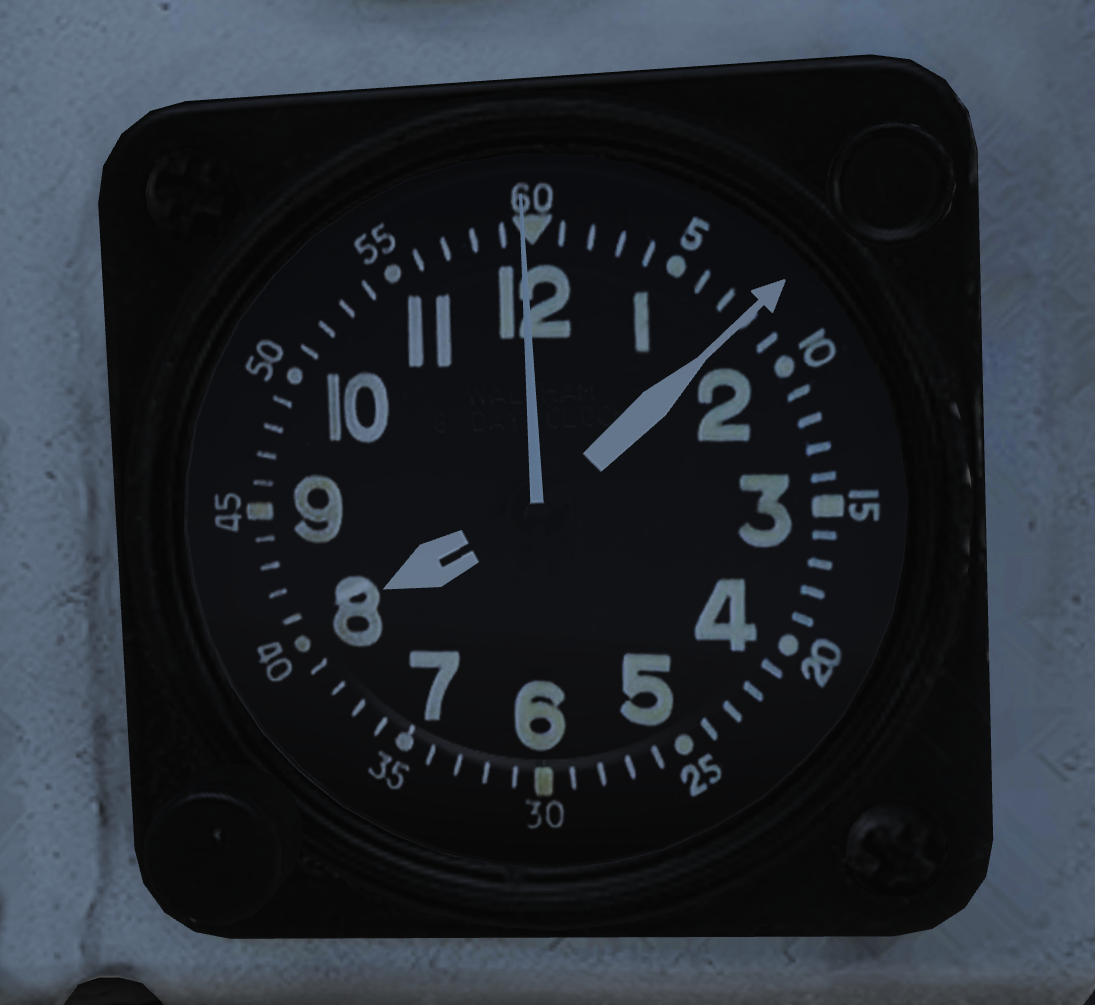 Mechanical wind-up clock.
The knob on the lower left corner is used to wind up the clock by turning it clockwise and pulled out and turned to set the hour and minute hands.
The control on the upper right corner is used to start, stop, and reset a 1-hour elapsed time counter.
Spoiler Failure Override
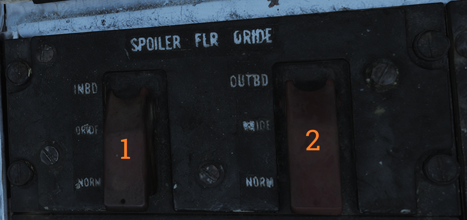 Contains controls to override failed spoiler sections, allowing the rest to continue to work after a MASTER RESET.
| No. | Control/Indicator | Function |
|---|---|---|
| 1 | INBD | Inboard spoiler override switch. ORIDE - Overrides inboard spoiler symmetry protection, allowing a functional inboard spoiler to continue to operate after a MASTER RESET if one fails. NORM - Normal (guarded position), in this mode, if an inboard spoiler fails up the rest are commanded to droop and the SPOILERS light illuminates on the caution panel. |
| 2 | OUTBD | Outboard spoiler override switch. ORIDE - Overrides outboard spoiler symmetry protection, allowing a functional outboard spoiler to continue to operate after a MASTER RESET if one fails. NORM - Normal (guarded position), in this mode, if an outboard spoiler fails up the rest are commanded to droop and the SPOILERS light illuminates on the caution panel. |
Liquid Oxygen Quantity Indicator
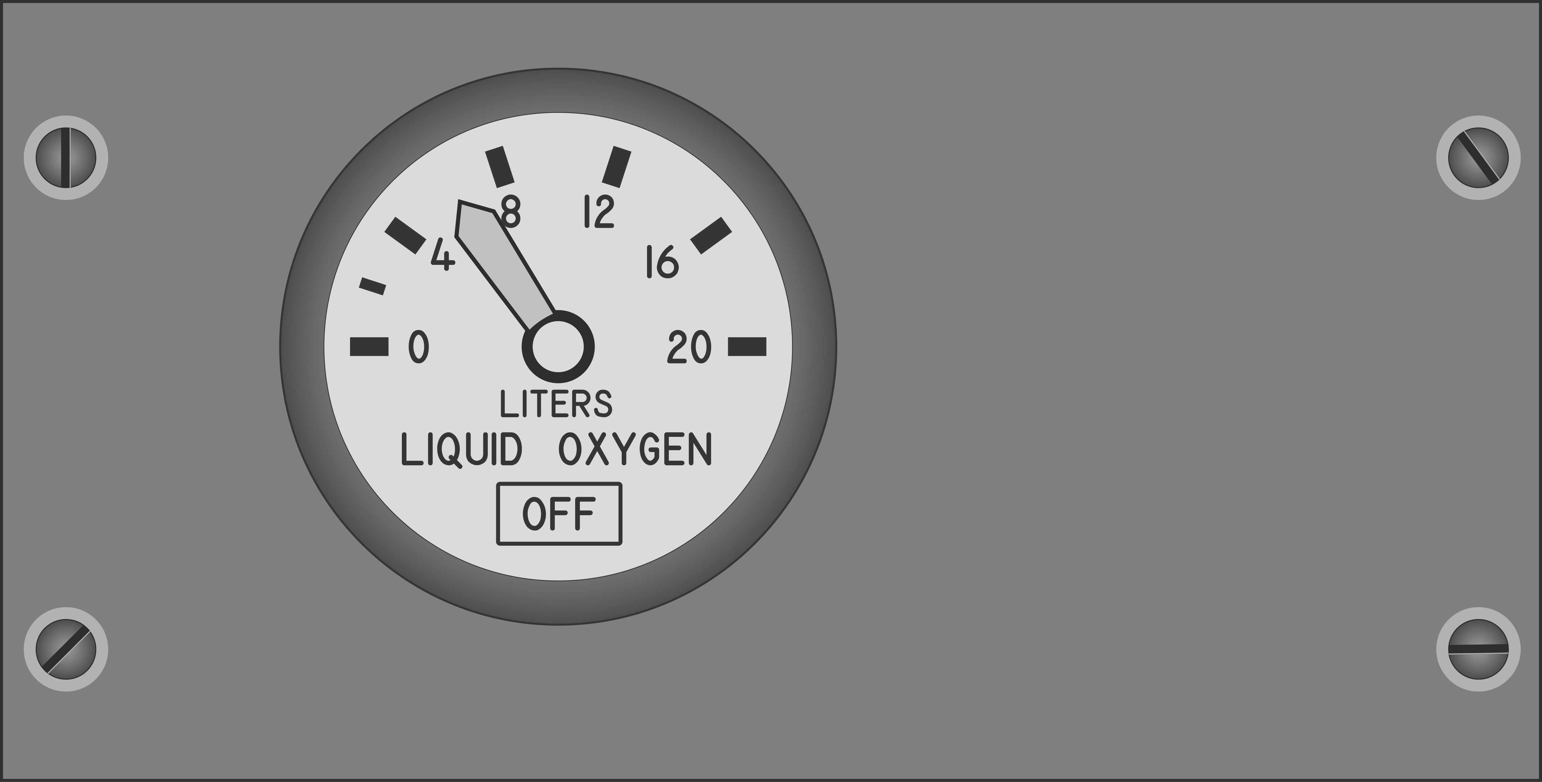 Contains an indicator showing the remaining quantity of liquid oxygen available. Graduated in 1-liter increments. Also has an OFF flag that is shown in case of power failure to the indicator. The indicator is tested through the INST mode on the MASTER TEST panel and should read 2 liters.
Compass Control Panel
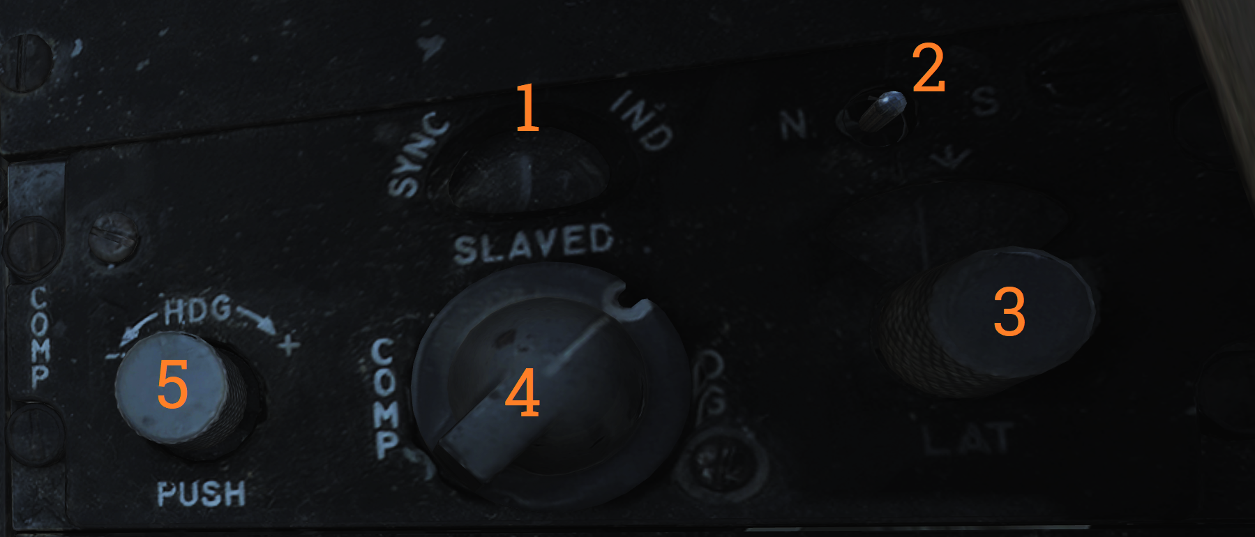 The compass control panel contains controls for selecting compass mode when using AHRS.
| No. | Control/Indicator | Function |
|---|---|---|
| 1 | SYNC IND | Indicator showing sync between AHRS gyro and magnetic azimuth detector. Used in SLAVED mode. |
| 2 | N-S switch | Switch used to select which hemisphere aircraft is in for DG and SLAVED modes. Critical for correct earth-rate correction. |
| 3 | LAT knob | Control knob used to select latitude from 0º to 90º to allow for correct earth-rate correction in DG and SLAVED modes. |
| 4 | Mode switch | Selects source of AHRS heading information. COMP - Compass, uses magnetic azimuth detector directly without stabilization from the directional gyro, used only for emergency operation and the displays automatically use the manual magnetic variation. SLAVED - Normal mode, uses the magnetic azimuth detector stabilized by the directional gyro. DG - Directional gyro mode, uses only the gyro and not the magnetic azimuth detector. |
| 5 | HDG knob/button | Used in DG and SLAVED modes. In SLAVED mode it’s used to sync the directional gyro with the magnetic azimuth detector and set magnetic heading on the BDHI. Button should be held until the synchronization indicator needle is over the null mark. In DG mode the button is depressed and rotated to select desired heading on the BDHI. The button can also be used to fast erect pitch and roll of the AHRS by depressing the button for up to 3 minutes. A new fast erect attempt can be done if a 1-minute wait is first observed. |
ARA-63 Control Panel
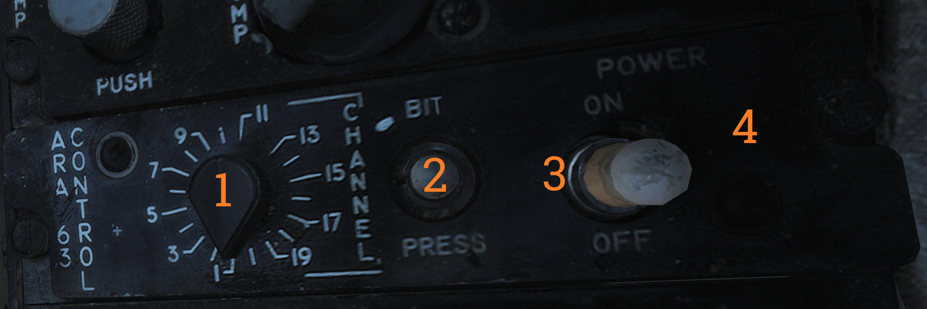 Panel used to control the AN/ARA-63 ILS (ICLS).
| No. | Control/Indicator | Function |
|---|---|---|
| 1 | CHANNEL selector | Selector selecting one of 20 available ICLS channels. |
| 2 | BIT button | Button used to test AN/ARA-63, displays landing symbology on the HUD and VDI if set up for ILS. |
| 3 | POWER switch | ON/OFF switch to energize the AN/ARA-63, switch must be pulled out to allow OFF position. |
| 4 | Indicator light | Lights to indicate AN/ARA-63 power on. |
Caution - Advisory Indicator
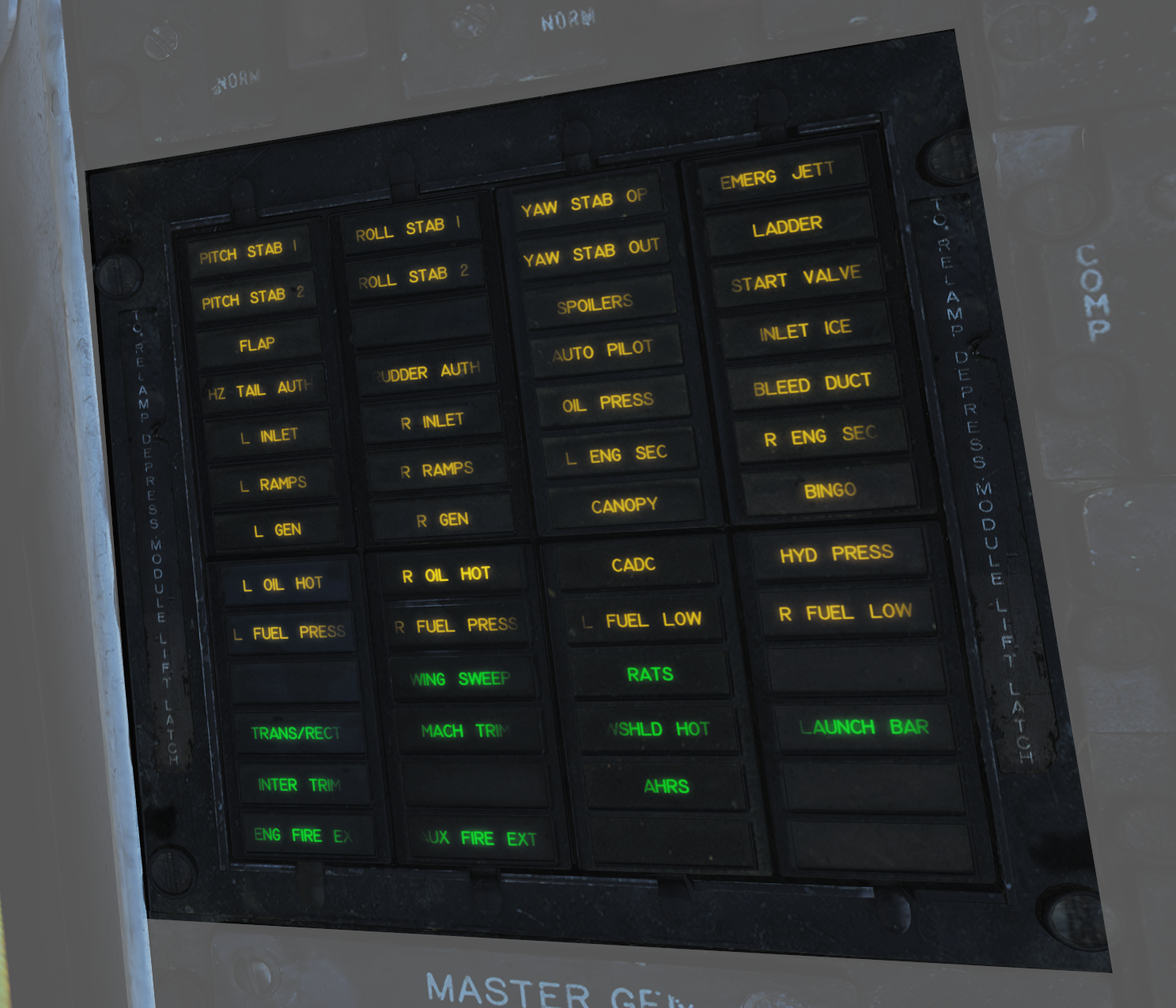 Main pilot caution panel.
| No. | Indicator | Function |
|---|---|---|
| 1 | PITCH STAB 1 & 2 | Caution lights indicating inoperative pitch channels. |
| 2 | ROLL STAB 1 & 2 | Caution lights indicating inoperative roll channels (roll SAS failure). |
| 3 | YAW STAB OP | Caution light indicating one inoperative yaw channel. |
| 4 | YAW STAB OUT | Caution light indicating two inoperative yaw channels (yaw SAS failure). |
| 5 | EMERG JETT | Caution light indicating activation of EMERG STORES JETT button. |
| 6 | LADDER | Caution light indicating boarding ladder not correctly stowed. |
| 7 | ECS TURBINE | Non-functional |
| 8 | INLET ICE | Caution light indicating accumulation of ice on the ice detector in the left engine inlet. |
| 9 | FLAP | Caution light indicating failure in the flap system or airspeed greater than 225 knots indicated airspeed with flaps down. |
| 10 | HZ TAIL AUTH | Caution light indicating failure of lateral tail authority actuator (or CADC failure). |
| 11 | RUDDER AUTH | Caution light indicating failure of rudder authority actuators (or CADC failure). |
| 12 | SPOILERS | Caution light indicating spoiler system failure causing several or all spoilers to be locked down. |
| 13 | AUTO PILOT | Caution light indicating failure in the auto pilot system. |
| 14 | L & R INLET | Caution lights indicating AICS programmer and/or system failure. |
| 15 | OIL PRESS | Caution light indicating left or right engine oil pressure below 11 psi. |
| 16 | BLEED DUCT | Caution light indicating high-temperature air leak in the engine compartments. |
| 17 | L & R RAMPS | Caution lights indicating ramps not locked in position during critical flight conditions. |
| 18 | START VALVE | Caution light indicating that the starter solenoid air valve is open after start. (F-14B only.) |
| 19 | OXY LOW | Caution light indicating low oxygen pressure or less than 2 liters of oxygen remaining. (F-14A only.) |
| 20 | L & R ENG SEC | Caution lights indicating that respective engine AFTC is in secondary mode. (F-14B only.) |
| 21 | L & R OVSP/VALVE | Caution lights indicating engine starter system malfunction or N1 rotor overspeed in respective engine. (F-14A only.) |
| 22 | L & R GEN | Caution lights indicating respective engine generator is inoperative. |
| 23 | CANOPY | Caution light indicating that the canopy is not down and locked. |
| 24 | BINGO | Caution light indicating aircraft fuel quantity at or below set BINGO quantity. |
| 25 | L & R OIL HOT | Caution lights indicating that respective engine oil is too hot. |
| 26 | CADC | Caution light indicating failure in the air data computer. |
| 27 | HYD PRESS | Caution light indicating pressure in either engine hydraulic pump below 2,100 psi. |
| 28 | L & R FUEL PRESS | Caution lights indicating pressure below 9 psi in the respective engine fuel boost pump. |
| 29 | L & R FUEL LOW | Caution lights indicating fuel quantity below 1,000 pounds in aft and left or forward and right fuel feed group respectively. |
| 30 | WING SWEEP | Advisory light indicating failure of a single channel in the wing-sweep system. |
| 31 | RATS | Advisory light indicating RATS enabled. (F-14B only.) |
| 32 | TRANS/RECT | Advisory light indicating failure in one or both transformer-rectifiers. |
| 33 | MACH TRIM | Advisory light indicating failure in Mach trim actuator. |
| 34 | WSHLD HOT | Advisory light indicating central windshield overheat. |
| 35 | LAUNCH BAR | Advisory light indicating either: Weight on wheels - Aircraft kneeled, either throttle below MIL and launch bar not up and locked. Weight off wheels - Launch bar not up and locked, launch bar not within 15º of center (cocked nosegear), or nose strut not fully extended. |
| 36 | INTEG TRIM | Advisory light indicating failure in the trim system or computer failure. |
| 37 | AHRS | Advisory light indicating unreliable attitude or heading information from AHRS. |
| 38 | ENG FIRE EXT | Advisory light indicating low pressure in the fire extinguishing container (90 psi below nominal 600 psi). |
| 39 | AUX FIRE EXT | Advisory light indicating low pressure in the auxiliary fire extinguishing container (90 psi below nominal 600 psi). |
Note: F-14A specific lights not yet implemented.
Master Generator Control Panel
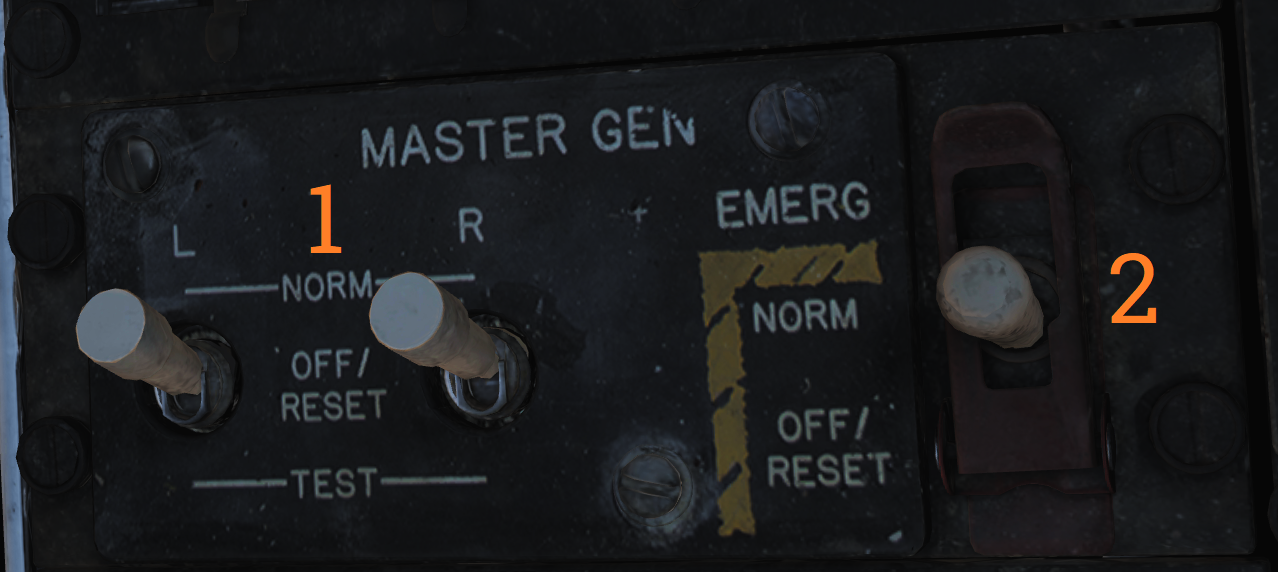 Panel controlling left and right engine generator.
| No. | Control/Indicator | Function |
|---|---|---|
| 1 | L & R MASTER GEN switch | Switches controlling connection and test of respective generator. Switch needs to be lifted to move from OFF/RESET. NORM - Normal, activating and connecting the generator to the main buses. OFF/RESET - Disconnects and deactivates the generator and resets tripped protection circuits. TEST - Activates the generator but does not connect it to the main buses, for testing purposes. |
| 2 | EMERG switch | Guarded switch controlling connection of the emergency generator to the essential buses. (Guarded position is NORM) NORM - Normal, the generator is automatically connected to essential buses if both main generators fail. OFF/RESET - Disconnects the generator from the essential buses regardless of the main generator status. Resets protection circuits. |
Master Light Control Panel
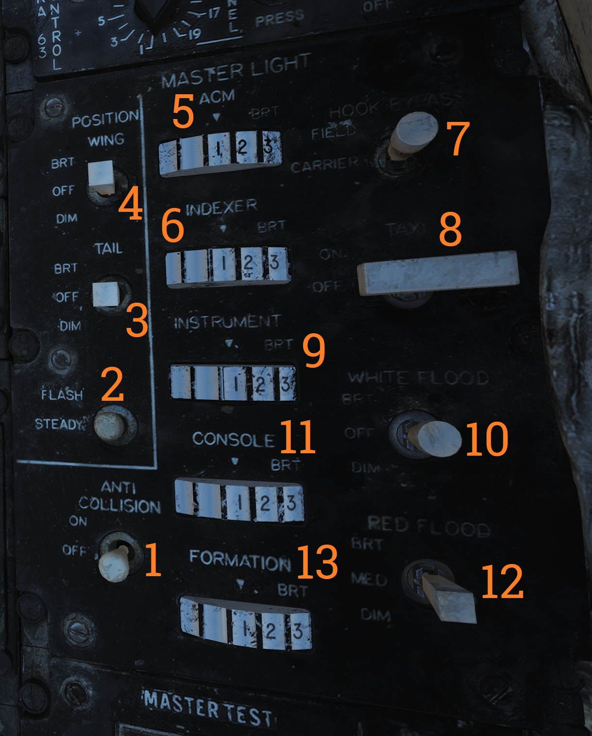 Master light control panel, controlling most lights in/on the aircraft.
| No. | Control/Indicator | Function |
|---|---|---|
| 1 | ANTI COLLISION switch | ON/OFF switch controlling anticollision lights. |
| 2 | POSITION switch | Switch controlling whether the wing or supplementary tail and position lights light up steadily or flash. With weight on wheels, the supplementary lights are always steady. |
| 3 | TAIL POSITION switch | Switch controlling tail position lights, DIM and BRT (bright) settings available. |
| 4 | WING POSITION switch | Switch controlling wing position lights, DIM and BRT settings available. |
| 5 | ACM thumbwheel | Thumbwheel controlling ACM panel lights, 0 equals off, 1-14 sets the lights to an increasingly bright setting. |
| 6 | INDEXER thumbwheel | Thumbwheel controlling AoA-indexer light intensity from 0-14. |
| 7 | HOOK BYPASS | Sets AOA lights to either FIELD or CARRIER mode, with the switch in CARRIER and wheels down, the AOA lights flash if the hook isn’t down. |
| 8 | TAXI switch | Switch controlling taxi lights. |
| 9 | INSTRUMENT thumbwheel | Thumbwheel controlling instrument panel lights, 0 equals off, 1-14 sets the lights to an increasingly bright setting. |
| 10 | WHITE FLOOD switch | Switch enabling white flood lights in the pilot cockpit. DIM and BRT settings available, switch locked to OFF unless pulled out. |
| 11 | CONSOLE thumbwheel | Thumbwheel controlling console lights and red floodlights. 0 turns off both console and red floodlights, 1-14 sets the console lights to an increasingly bright setting. |
| 12 | RED FLOOD switch | Switch controlling red instrument and console floodlights. BRT - Sets bright red instrument flood and console lights. MED - Red console floodlights. DIM - Dim red console floodlights. |
| 13 | FORMATION thumbwheel | Thumbwheel controlling external formation lights. 0 equals off, 1-14 sets the lights to an increasingly bright setting. |
Air Conditioning Control Panel
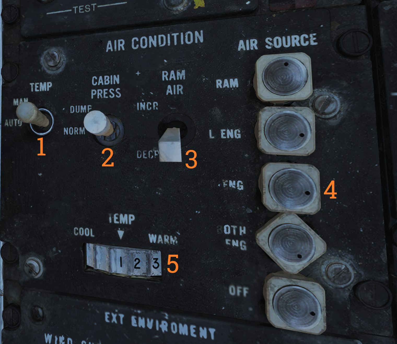 Panel controlling the environmental control system (ECS).
| No. | Control/Indicator | Function |
|---|---|---|
| 1 | TEMP switch | Switch controlling the cabin and pressure suit temperature mode. AUTO - Temperature is automatically set from the TEMP thumbwheel regardless of airspeed and altitude. MAN - Temperature is manually set from the TEMP thumbwheel but varies with airspeed and altitude and might need to be reset. |
| 2 | CABIN PRESS switch | Switch controlling cabin pressurization. Locked to NORM until lifted. NORM - Normal mode, cabin is pressurized at a level of 8,000 feet up to an aircraft level of 23,000 feet, after which it maintains a 5 psi difference from outside atmosphere. DUMP - Opens the cockpit dump valve depressurizing the cockpit. |
| 3 | RAM AIR switch | Selector switch used to modulate the amount of air from the ram air door after AIR SOURCE is set to RAM or OFF. Can be held to INCR (increase) or DECR (decrease), spring-loaded back to center. |
| 4 | AIR SOURCE selectors | Five mutually exclusive air source selectors. Rotates to indicate selection. RAM - Closes other air sources and opens the ram air door which is combined with hot bleed air to supply all users. L & R ENG - Selects either engine as the source for bleed air. BOTH ENG - Selects both engines as source for bleed air. Normal position. OFF - Closes all air sources but the ram air door. In this mode the ram air door cannot supply pressurization or air conditioning. Inhibits gun firing. |
| 5 | TEMP thumbwheel | Selects cockpit and pressure suit air temperature. 0-14 is selectable with COOL and WARM placarded at each end stop. In auto 7 approximately corresponds to 21º C or 70º F. In manual the thumbwheel needs to be set for each variation in airspeed and altitude. |
Master Test Panel
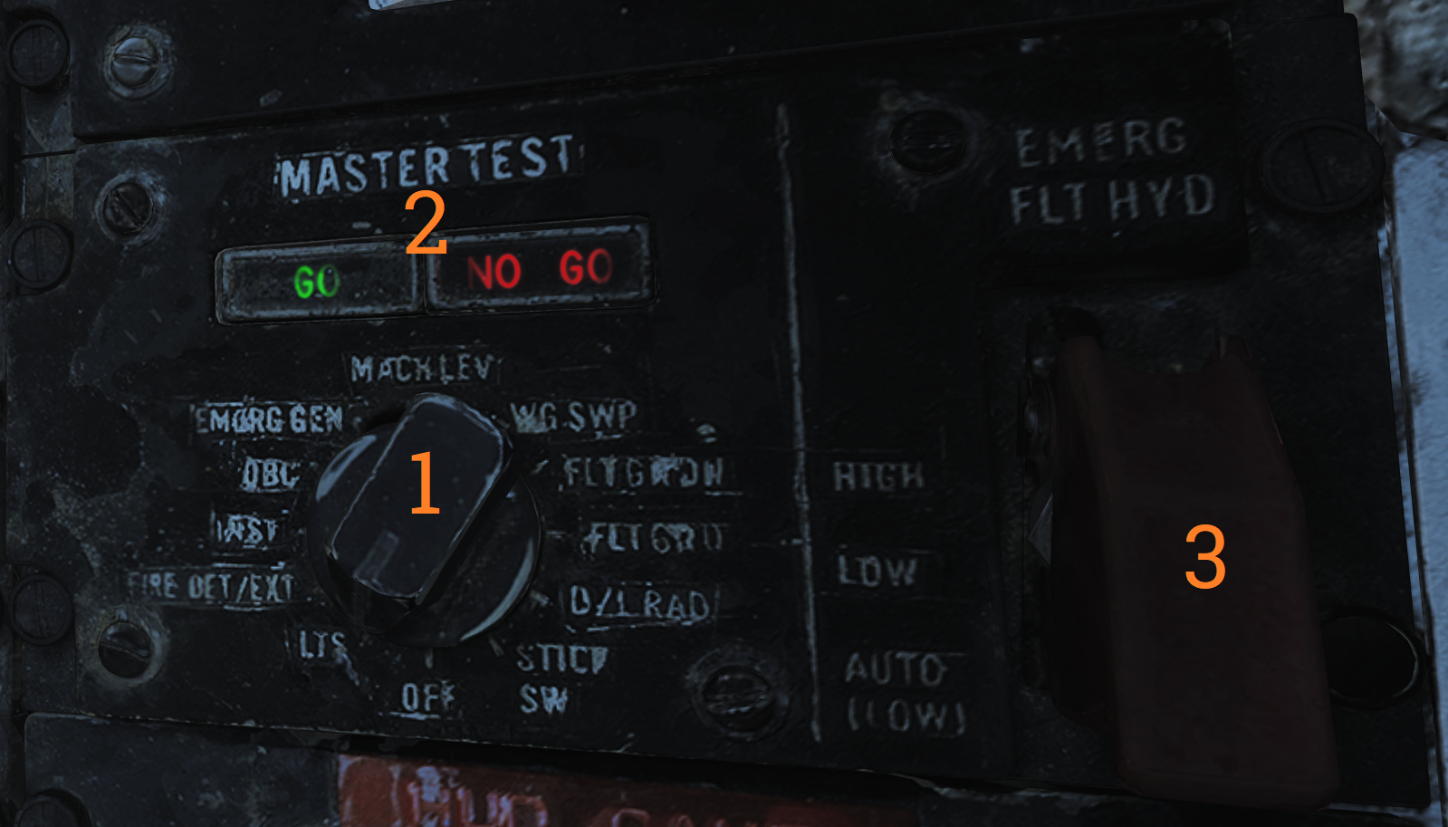 Panel controlling OBC and various onboard BITs in addition to the emergency flight hydraulic setting.
| No. | Control/Indicator | Function |
|---|---|---|
| 1 | MASTER TEST selector | Selector used to select and initiate OBC and BIT for various systems. Pull out to enable selection, push in at selected option to start test. OFF - Disables test functions. LTS - Lights, tests cockpit indication lights. FIRE DET/EXT - Fire detection system test. INST - Instruments, tests various cockpit instrumentation. OBC - Onboard checkout, starts OBC. EMERG GEN - Tests emergency generator. MACH LEV - Initiates dynamic MACH lever check. F-14A only. WG SWP - Tests wing-sweep system. FLT GR DN - Initiates ground check of auto throttle interlocks. FLT GR UP - Tests external fuel tank pressurization. D/L RAD - Tests the data link converter. STICK SW - Checks left and right spoiler symmetry switches and 1-inch stick switches for yaw SAS. |
| 2 | GO/NO-GO lights | Lights used in relevant tests to indicate GO or NO-GO conditions of those systems. |
| 3 | EMERG FLT HYD | Switch controlling the emergency mode of the flight hydraulic system. Guarded to the AUTO (LOW) position. HIGH - Activates the power module (high-speed mode), bypassing flight and combined 2,100 psi switches. LOW - Activates the backup power module bypassing flight and combined 2,100 psi switches. AUTO (LOW) - Automatically activates LOW mode when both flight and combined system pressures are below 2,100 psi. |
Note: Specific tests will be detailed in a future BIT chapter.
External Environmental Control Panel
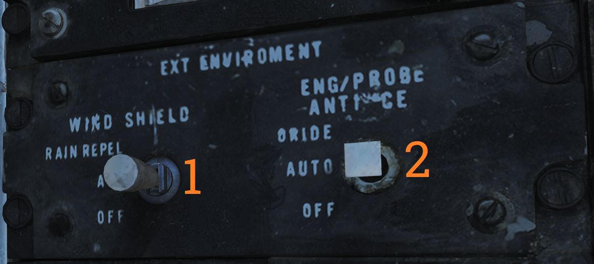 Panel controlling windshield air and external anti-ice settings.
| No. | Control/Indicator | Function |
|---|---|---|
| 1 | WSHLD switch | Switch controlling external heating of the windshield by blasting the exterior with warm air. AIR - Enables system. OFF - Disables system. |
| 2 | ANTI-ICE switch | Controls engine, probe, and AICS anti-ice settings. ORIDE/ON - Engages engine and probe anti-ice regardless of external conditions and enables the anti-ice setting in AICS. AUTO/OFF - Automatically engages engine and probe anti-ice as needed, turns off AICS anti-ice. OFF/OFF - Turns off both engine and probe anti-ice and AICS anti-ice. |
Hydraulic Transfer Pump Switch
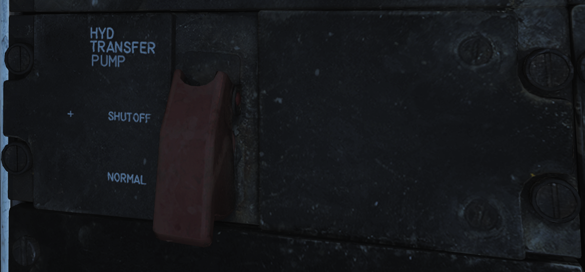 Panel containing the control for the hydraulic transfer pump which equalizes pressure between the combined and flight hydraulic systems in case of a failure in one of them.
The HYD TRANSFER PUMP switch has two positions, SHUTOFF and NORMAL (guarded position). The NORMAL position (also the standard setting) will have the hydraulic transfer pump pressurize a failed hydraulic system from the other, functioning system, when it drops below 2,100 psi. The SHUTOFF position (which can be accessed by lifting the guard) is used to turn off the transfer pump in case it can’t supply enough pressure to the failed system as that would risk disabling the still operational system.
HUD-Video Control Panel
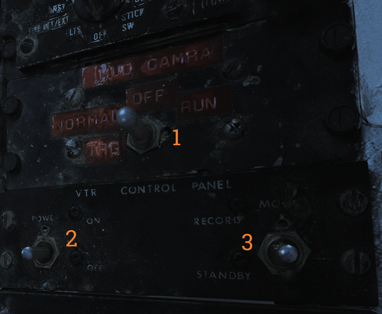 Control panel for the CTVS system which records the HUD when activated. Not implemented in DCS.
| No. | Control/Indicator | Function |
|---|---|---|
| 1 | HUD CAM(E)RA switch | TRG - Trigger, records while the second (firing) detent on the stick trigger is depressed. NORMAL - Records while the first detent on the stick trigger is depressed. OFF - Disables power to the CTVS. RUN - Records continuously. |
| 2 | Switch 2 & 3. | VTR - Video tape recorder. |
Canopy Defog/Cabin Air Lever
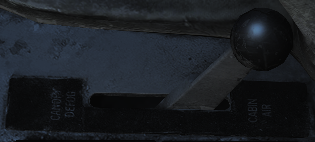 The canopy air diffuser lever controls the flow of cabin air. The normal position, CABIN AIR, directs 70% of the conditioned air through the cockpit air diffusers and 30% through the canopy air diffusers. The CANOPY DEFOG position directs all airflow through the canopy air diffusers for canopy defog.
Canopy Control Handle
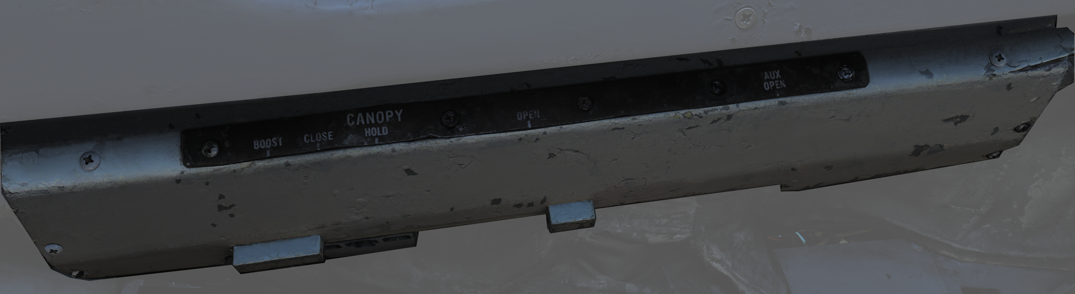 The canopy control handle controls canopy operation and is located on the right cockpit wall. The handle is mounted downwards beneath the box containing the handle mechanism and the handle position texts. The canopy control handle is duplicated in the RIO cockpit.
| No. | Control | Function |
|---|---|---|
| 1 | BOOST | Closes the canopy using boost, used during cold weather or with a strong headwind. |
| 2 | CLOSE | Closes the canopy, default position during flight. |
| 3 | HOLD | Holds the canopy at the current position for any position other than closed. |
| 4 | OPEN | Opens the canopy. |
| 5 | AUX OPEN | Allows manual opening of the canopy if system pressure is too low. |
Right Side Console
Spoiler Failure Override
Contains controls to override failed spoiler sections, allowing the rest to continue to work after a MASTER RESET.
| No. | Control/Indicator | Function |
|---|---|---|
| 1 | INBD | Inboard spoiler override switch. ORIDE - Overrides inboard spoiler symmetry protection, allowing a functional inboard spoiler to continue to operate after a MASTER RESET if one fails. NORM - Normal (guarded position), in this mode, if an inboard spoiler fails up the rest are commanded to droop and the SPOILERS light illuminates on the caution panel. |
| 2 | OUTBD | Outboard spoiler override switch. ORIDE - Overrides outboard spoiler symmetry protection, allowing a functional outboard spoiler to continue to operate after a MASTER RESET if one fails. NORM - Normal (guarded position), in this mode, if an outboard spoiler fails up the rest are commanded to droop and the SPOILERS light illuminates on the caution panel. |
Liquid Oxygen Quantity Indicator
Contains an indicator showing the remaining quantity of liquid oxygen available. Graduated in 1-liter increments. Also has an OFF flag that is shown in case of power failure to the indicator. The indicator is tested through the INST mode on the MASTER TEST panel and should read 2 liters.
Compass Control Panel
The compass control panel contains controls for selecting compass mode when using AHRS.
| No. | Control/Indicator | Function |
|---|---|---|
| 1 | SYNC IND | Indicator showing sync between AHRS gyro and magnetic azimuth detector. Used in SLAVED mode. |
| 2 | N-S switch | Switch used to select which hemisphere aircraft is in for DG and SLAVED modes. Critical for correct earth-rate correction. |
| 3 | LAT knob | Control knob used to select latitude from 0º to 90º to allow for correct earth-rate correction in DG and SLAVED modes. |
| 4 | Mode switch | Selects source of AHRS heading information. COMP - Compass, uses magnetic azimuth detector directly without stabilization from the directional gyro, used only for emergency operation and the displays automatically use the manual magnetic variation. SLAVED - Normal mode, uses the magnetic azimuth detector stabilized by the directional gyro. DG - Directional gyro mode, uses only the gyro and not the magnetic azimuth detector. |
| 5 | HDG knob/button | Used in DG and SLAVED modes. In SLAVED mode it’s used to sync the directional gyro with the magnetic azimuth detector and set magnetic heading on the BDHI. Button should be held until the synchronization indicator needle is over the null mark. In DG mode the button is depressed and rotated to select desired heading on the BDHI. The button can also be used to fast erect pitch and roll of the AHRS by depressing the button for up to 3 minutes. A new fast erect attempt can be done if a 1-minute wait is first observed. |
ARA-63 Control Panel
Panel used to control the AN/ARA-63 ILS (ICLS).
| No. | Control/Indicator | Function |
|---|---|---|
| 1 | CHANNEL selector | Selector selecting one of 20 available ICLS channels. |
| 2 | BIT button | Button used to test AN/ARA-63, displays landing symbology on the HUD and VDI if set up for ILS. |
| 3 | POWER switch | ON/OFF switch to energize the AN/ARA-63, switch must be pulled out to allow OFF position. |
| 4 | Indicator light | Lights to indicate AN/ARA-63 power on. |
Caution - Advisory Indicator
Main pilot caution panel.
| No. | Indicator | Function |
|---|---|---|
| 1 | PITCH STAB 1 & 2 | Caution lights indicating inoperative pitch channels. |
| 2 | ROLL STAB 1 & 2 | Caution lights indicating inoperative roll channels (roll SAS failure). |
| 3 | YAW STAB OP | Caution light indicating one inoperative yaw channel. |
| 4 | YAW STAB OUT | Caution light indicating two inoperative yaw channels (yaw SAS failure). |
| 5 | EMERG JETT | Caution light indicating activation of EMERG STORES JETT button. |
| 6 | LADDER | Caution light indicating boarding ladder not correctly stowed. |
| 7 | ECS TURBINE | Non-functional |
| 8 | INLET ICE | Caution light indicating accumulation of ice on the ice detector in the left engine inlet. |
| 9 | FLAP | Caution light indicating failure in the flap system or airspeed greater than 225 knots indicated airspeed with flaps down. |
| 10 | HZ TAIL AUTH | Caution light indicating failure of lateral tail authority actuator (or CADC failure). |
| 11 | RUDDER AUTH | Caution light indicating failure of rudder authority actuators (or CADC failure). |
| 12 | SPOILERS | Caution light indicating spoiler system failure causing several or all spoilers to be locked down. |
| 13 | AUTO PILOT | Caution light indicating failure in the auto pilot system. |
| 14 | L & R INLET | Caution lights indicating AICS programmer and/or system failure. |
| 15 | OIL PRESS | Caution light indicating left or right engine oil pressure below 11 psi. |
| 16 | BLEED DUCT | Caution light indicating high-temperature air leak in the engine compartments. |
| 17 | L & R RAMPS | Caution lights indicating ramps not locked in position during critical flight conditions. |
| 18 | START VALVE | Caution light indicating that the starter solenoid air valve is open after start. (F-14B only.) |
| 19 | OXY LOW | Caution light indicating low oxygen pressure or less than 2 liters of oxygen remaining. (F-14A only.) |
| 20 | L & R ENG SEC | Caution lights indicating that respective engine AFTC is in secondary mode. (F-14B only.) |
| 21 | L & R OVSP/VALVE | Caution lights indicating engine starter system malfunction or N1 rotor overspeed in respective engine. (F-14A only.) |
| 22 | L & R GEN | Caution lights indicating respective engine generator is inoperative. |
| 23 | CANOPY | Caution light indicating that the canopy is not down and locked. |
| 24 | BINGO | Caution light indicating aircraft fuel quantity at or below set BINGO quantity. |
| 25 | L & R OIL HOT | Caution lights indicating that respective engine oil is too hot. |
| 26 | CADC | Caution light indicating failure in the air data computer. |
| 27 | HYD PRESS | Caution light indicating pressure in either engine hydraulic pump below 2,100 psi. |
| 28 | L & R FUEL PRESS | Caution lights indicating pressure below 9 psi in the respective engine fuel boost pump. |
| 29 | L & R FUEL LOW | Caution lights indicating fuel quantity below 1,000 pounds in aft and left or forward and right fuel feed group respectively. |
| 30 | WING SWEEP | Advisory light indicating failure of a single channel in the wing-sweep system. |
| 31 | RATS | Advisory light indicating RATS enabled. (F-14B only.) |
| 32 | TRANS/RECT | Advisory light indicating failure in one or both transformer-rectifiers. |
| 33 | MACH TRIM | Advisory light indicating failure in Mach trim actuator. |
| 34 | WSHLD HOT | Advisory light indicating central windshield overheat. |
| 35 | LAUNCH BAR | Advisory light indicating either: Weight on wheels - Aircraft kneeled, either throttle below MIL and launch bar not up and locked. Weight off wheels - Launch bar not up and locked, launch bar not within 15º of center (cocked nosegear), or nose strut not fully extended. |
| 36 | INTEG TRIM | Advisory light indicating failure in the trim system or computer failure. |
| 37 | AHRS | Advisory light indicating unreliable attitude or heading information from AHRS. |
| 38 | ENG FIRE EXT | Advisory light indicating low pressure in the fire extinguishing container (90 psi below nominal 600 psi). |
| 39 | AUX FIRE EXT | Advisory light indicating low pressure in the auxiliary fire extinguishing container (90 psi below nominal 600 psi). |
Note: F-14A specific lights not yet implemented.
Master Generator Control Panel
Panel controlling left and right engine generator.
| No. | Control/Indicator | Function |
|---|---|---|
| 1 | L & R MASTER GEN switch | Switches controlling connection and test of respective generator. Switch needs to be lifted to move from OFF/RESET. NORM - Normal, activating and connecting the generator to the main buses. OFF/RESET - Disconnects and deactivates the generator and resets tripped protection circuits. TEST - Activates the generator but does not connect it to the main buses, for testing purposes. |
| 2 | EMERG switch | Guarded switch controlling connection of the emergency generator to the essential buses. (Guarded position is NORM) NORM - Normal, the generator is automatically connected to essential buses if both main generators fail. OFF/RESET - Disconnects the generator from the essential buses regardless of the main generator status. Resets protection circuits. |
Master Light Control Panel
Master light control panel, controlling most lights in/on the aircraft.
| No. | Control/Indicator | Function |
|---|---|---|
| 1 | ANTI COLLISION switch | ON/OFF switch controlling anticollision lights. |
| 2 | POSITION switch | Switch controlling whether the wing or supplementary tail and position lights light up steadily or flash. With weight on wheels, the supplementary lights are always steady. |
| 3 | TAIL POSITION switch | Switch controlling tail position lights, DIM and BRT (bright) settings available. |
| 4 | WING POSITION switch | Switch controlling wing position lights, DIM and BRT settings available. |
| 5 | ACM thumbwheel | Thumbwheel controlling ACM panel lights, 0 equals off, 1-14 sets the lights to an increasingly bright setting. |
| 6 | INDEXER thumbwheel | Thumbwheel controlling AoA-indexer light intensity from 0-14. |
| 7 | HOOK BYPASS | Sets AOA lights to either FIELD or CARRIER mode, with the switch in CARRIER and wheels down, the AOA lights flash if the hook isn’t down. |
| 8 | TAXI switch | Switch controlling taxi lights. |
| 9 | INSTRUMENT thumbwheel | Thumbwheel controlling instrument panel lights, 0 equals off, 1-14 sets the lights to an increasingly bright setting. |
| 10 | WHITE FLOOD switch | Switch enabling white flood lights in the pilot cockpit. DIM and BRT settings available, switch locked to OFF unless pulled out. |
| 11 | CONSOLE thumbwheel | Thumbwheel controlling console lights and red floodlights. 0 turns off both console and red floodlights, 1-14 sets the console lights to an increasingly bright setting. |
| 12 | RED FLOOD switch | Switch controlling red instrument and console floodlights. BRT - Sets bright red instrument flood and console lights. MED - Red console floodlights. DIM - Dim red console floodlights. |
| 13 | FORMATION thumbwheel | Thumbwheel controlling external formation lights. 0 equals off, 1-14 sets the lights to an increasingly bright setting. |
Air Conditioning Control Panel
Panel controlling the environmental control system (ECS).
| No. | Control/Indicator | Function |
|---|---|---|
| 1 | TEMP switch | Switch controlling the cabin and pressure suit temperature mode. AUTO - Temperature is automatically set from the TEMP thumbwheel regardless of airspeed and altitude. MAN - Temperature is manually set from the TEMP thumbwheel but varies with airspeed and altitude and might need to be reset. |
| 2 | CABIN PRESS switch | Switch controlling cabin pressurization. Locked to NORM until lifted. NORM - Normal mode, cabin is pressurized at a level of 8,000 feet up to an aircraft level of 23,000 feet, after which it maintains a 5 psi difference from outside atmosphere. DUMP - Opens the cockpit dump valve depressurizing the cockpit. |
| 3 | RAM AIR switch | Selector switch used to modulate the amount of air from the ram air door after AIR SOURCE is set to RAM or OFF. Can be held to INCR (increase) or DECR (decrease), spring-loaded back to center. |
| 4 | AIR SOURCE selectors | Five mutually exclusive air source selectors. Rotates to indicate selection. RAM - Closes other air sources and opens the ram air door which is combined with hot bleed air to supply all users. L & R ENG - Selects either engine as the source for bleed air. BOTH ENG - Selects both engines as source for bleed air. Normal position. OFF - Closes all air sources but the ram air door. In this mode the ram air door cannot supply pressurization or air conditioning. Inhibits gun firing. |
| 5 | TEMP thumbwheel | Selects cockpit and pressure suit air temperature. 0-14 is selectable with COOL and WARM placarded at each end stop. In auto 7 approximately corresponds to 21º C or 70º F. In manual the thumbwheel needs to be set for each variation in airspeed and altitude. |
Master Test Panel
Panel controlling OBC and various onboard BITs in addition to the emergency flight hydraulic setting.
| No. | Control/Indicator | Function |
|---|---|---|
| 1 | MASTER TEST selector | Selector used to select and initiate OBC and BIT for various systems. Pull out to enable selection, push in at selected option to start test. OFF - Disables test functions. LTS - Lights, tests cockpit indication lights. FIRE DET/EXT - Fire detection system test. INST - Instruments, tests various cockpit instrumentation. OBC - Onboard checkout, starts OBC. EMERG GEN - Tests emergency generator. MACH LEV - Initiates dynamic MACH lever check. F-14A only. WG SWP - Tests wing-sweep system. FLT GR DN - Initiates ground check of auto throttle interlocks. FLT GR UP - Tests external fuel tank pressurization. D/L RAD - Tests the data link converter. STICK SW - Checks left and right spoiler symmetry switches and 1-inch stick switches for yaw SAS. |
| 2 | GO/NO-GO lights | Lights used in relevant tests to indicate GO or NO-GO conditions of those systems. |
| 3 | EMERG FLT HYD | Switch controlling the emergency mode of the flight hydraulic system. Guarded to the AUTO (LOW) position. HIGH - Activates the power module (high-speed mode), bypassing flight and combined 2,100 psi switches. LOW - Activates the backup power module bypassing flight and combined 2,100 psi switches. AUTO (LOW) - Automatically activates LOW mode when both flight and combined system pressures are below 2,100 psi. |
Note: Specific tests will be detailed in a future BIT chapter.
External Environmental Control Panel
Panel controlling windshield air and external anti-ice settings.
| No. | Control/Indicator | Function |
|---|---|---|
| 1 | WSHLD switch | Switch controlling external heating of the windshield by blasting the exterior with warm air. AIR - Enables system. OFF - Disables system. |
| 2 | ANTI-ICE switch | Controls engine, probe, and AICS anti-ice settings. ORIDE/ON - Engages engine and probe anti-ice regardless of external conditions and enables the anti-ice setting in AICS. AUTO/OFF - Automatically engages engine and probe anti-ice as needed, turns off AICS anti-ice. OFF/OFF - Turns off both engine and probe anti-ice and AICS anti-ice. |
Hydraulic Transfer Pump Switch
Panel containing the control for the hydraulic transfer pump which equalizes pressure between the combined and flight hydraulic systems in case of a failure in one of them.
The HYD TRANSFER PUMP switch has two positions, SHUTOFF and NORMAL (guarded position). The NORMAL position (also the standard setting) will have the hydraulic transfer pump pressurize a failed hydraulic system from the other, functioning system, when it drops below 2,100 psi. The SHUTOFF position (which can be accessed by lifting the guard) is used to turn off the transfer pump in case it can’t supply enough pressure to the failed system as that would risk disabling the still operational system.
HUD-Video Control Panel
Control panel for the CTVS system which records the HUD when activated. Not implemented in DCS.
| No. | Control/Indicator | Function |
|---|---|---|
| 1 | HUD CAM(E)RA switch | TRG - Trigger, records while the second (firing) detent on the stick trigger is depressed. NORMAL - Records while the first detent on the stick trigger is depressed. OFF - Disables power to the CTVS. RUN - Records continuously. |
| 2 | Switch 2 & 3. | VTR - Video tape recorder. |
Canopy Defog/Cabin Air Lever
The canopy air diffuser lever controls the flow of cabin air. The normal position, CABIN AIR, directs 70% of the conditioned air through the cockpit air diffusers and 30% through the canopy air diffusers. The CANOPY DEFOG position directs all airflow through the canopy air diffusers for canopy defog.
Canopy Control Handle
The canopy control handle controls canopy operation and is located on the right cockpit wall. The handle is mounted downwards beneath the box containing the handle mechanism and the handle position texts. The canopy control handle is duplicated in the RIO cockpit.
| No. | Control | Function |
|---|---|---|
| 1 | BOOST | Closes the canopy using boost, used during cold weather or with a strong headwind. |
| 2 | CLOSE | Closes the canopy, default position during flight. |
| 3 | HOLD | Holds the canopy at the current position for any position other than closed. |
| 4 | OPEN | Opens the canopy. |
| 5 | AUX OPEN | Allows manual opening of the canopy if system pressure is too low. |
RIO Cockpit Layout
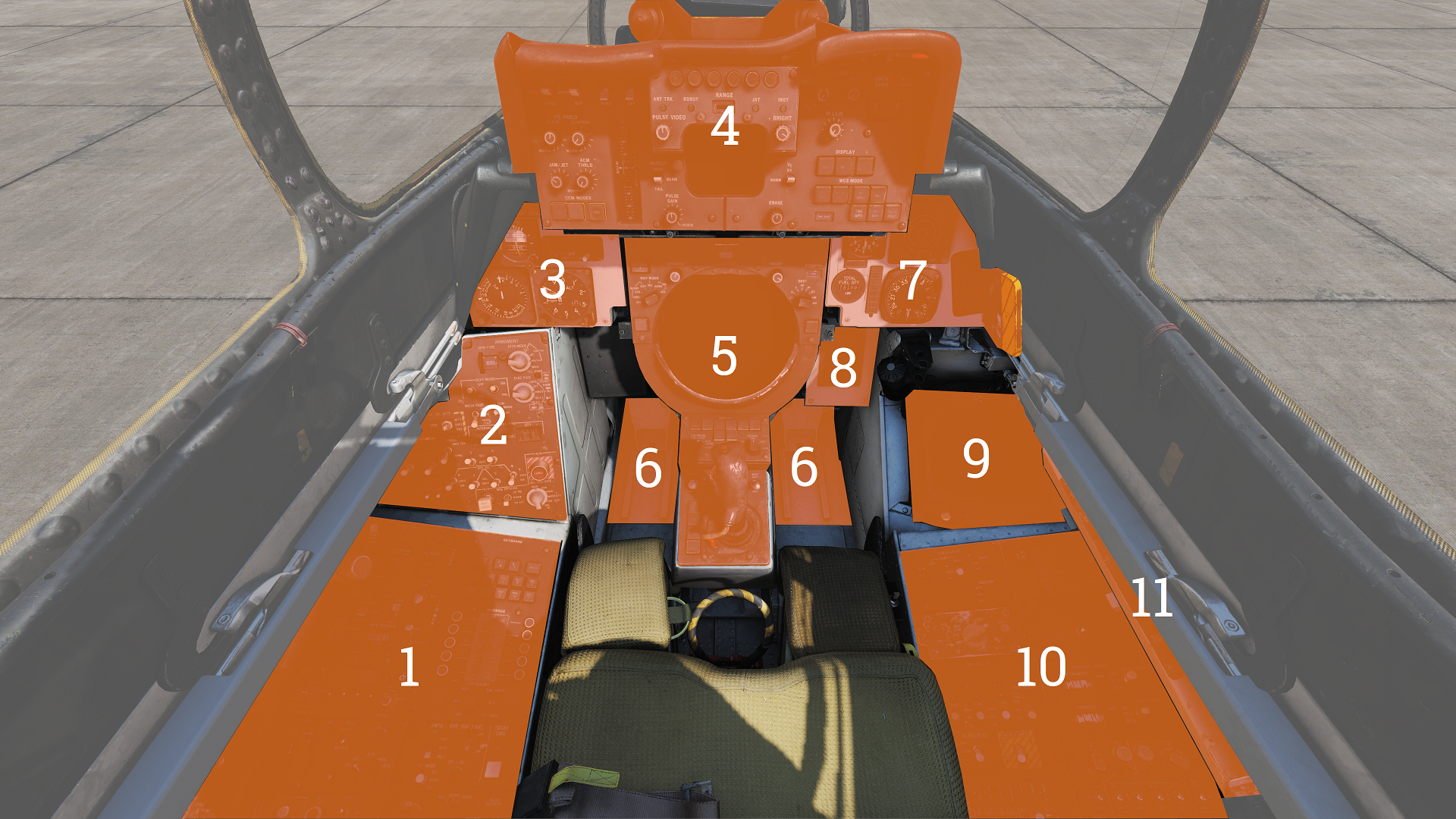
Left Side Console
G-Valve Button
 Pressed to test inflation of g-suit.
Oxygen-Vent Airflow Control Panel
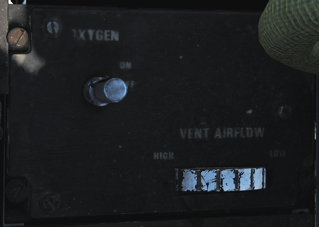 Controls ventilation airflow to pressure suit or seat cushions and oxygen to RIO mask.
| No. | Control | Function |
|---|---|---|
| 1 | VENT AIRFLOW dial | Used to control airflow through the pressure suit or seat cushions if no pressure suit is worn. |
| 2 | OXYGEN switch | Switch with ON/OFF positions. Controls oxygen flow to the mask. |
Data Stowage Compartment
 The data stowage panel is a small compartment for equipment storage and mission briefing materials etc.
TACAN Control Panel
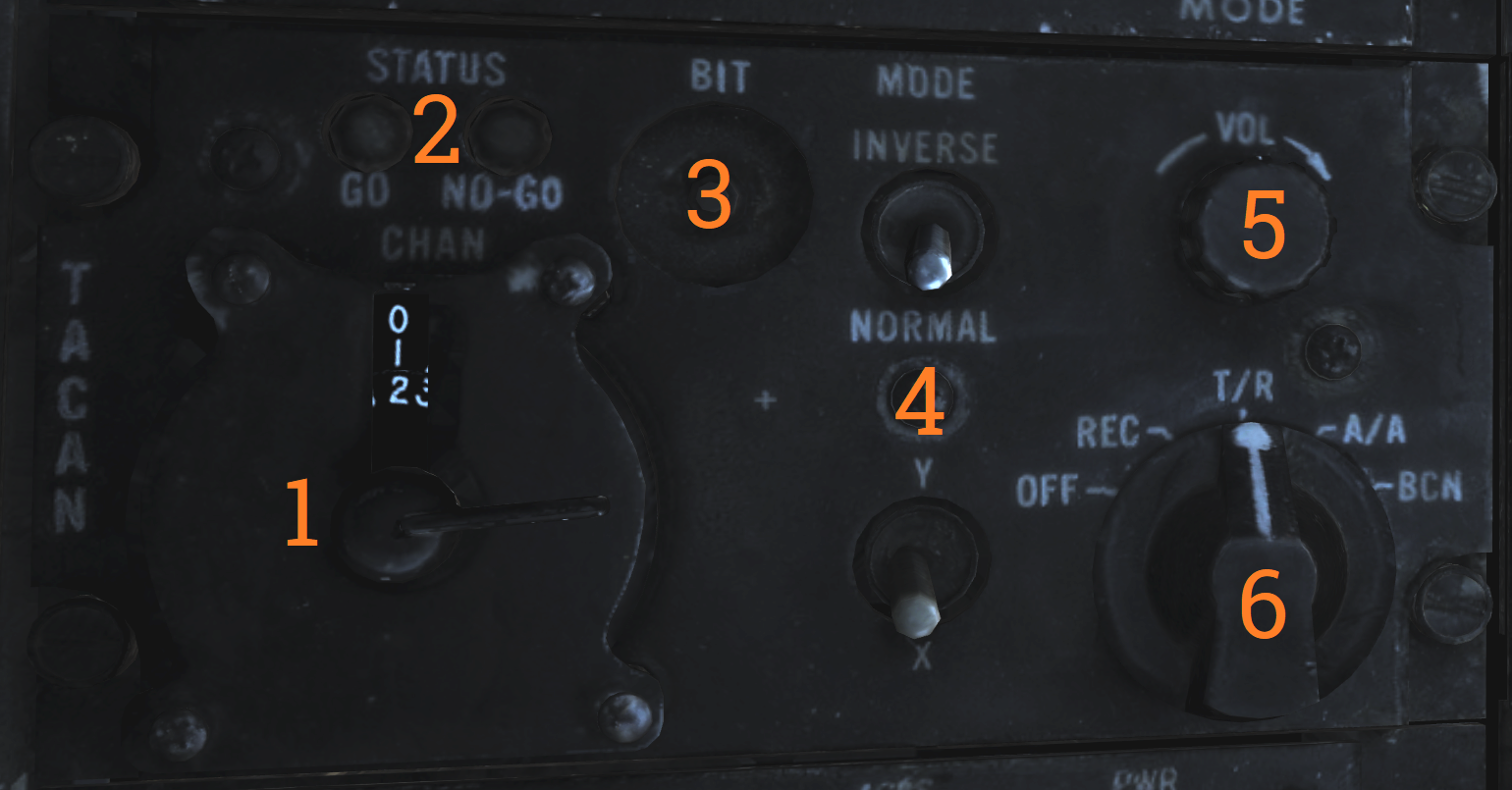 TACAN control panel letting the RIO control TACAN if in command of it.
| No. | Control/Indicator | Function |
|---|---|---|
| 1 | Dual rotary switch | Outer dial selects first two digits and inner dial selects last digit for TACAN channel selection. |
| 2 | GO & NO-GO lights | Lights indicating result of TACAN BIT. |
| 3 | BIT button | Button initiating TACAN BIT. |
| 4 | MODE switches | Switches mode for TACAN operation and selects X or Y channels. INVERSE mode not functional. |
| 5 | VOL knob | Volume control knob for TACAN audio to RIO. |
| 6 | Mode knob | Selects TACAN mode. OFF - TACAN is off. REC - Receive only. T/R - Transmit and receive, enables range readout. A/A - Air to air TACAN mode. BCN - Beacon TACAN mode. (Non-functional) |
Communication/TACAN Command Panel
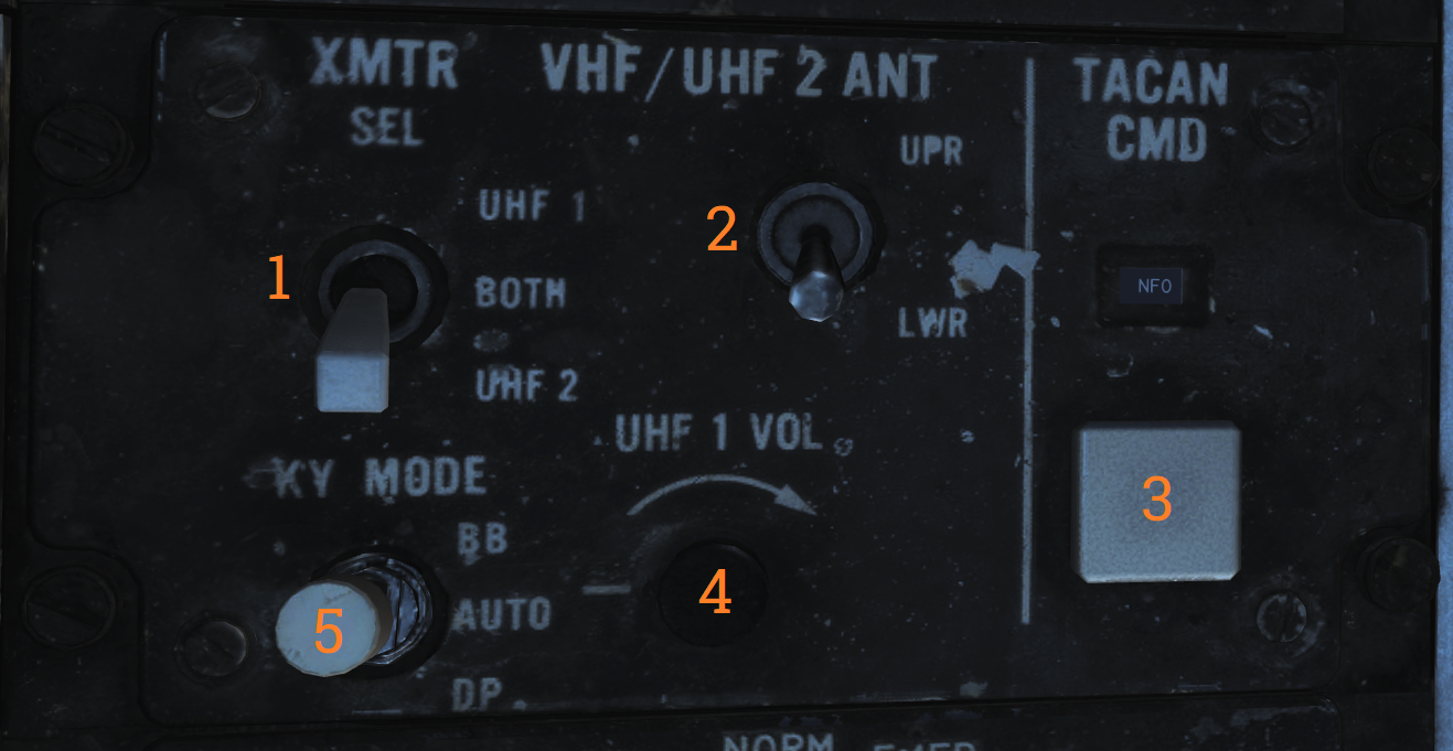 Panel controlling ICS radio settings and crewmember in control of TACAN.
| No. | Control/Indicator | Function |
|---|---|---|
| 1 | XMTR SEL switch | Selects which VHF/UHF radio the RIO PTT keys. UHF 1 - Selects the ARC-159 UHF radio. BOTH - Selects both radios. V/UHF 2 - Selects the ARC-182 VHF/UHF radio. |
| 2 | V/UHF 2 ANT switch | Selects which antenna the V/UHF 2 uses. UPR - Selects the upper antenna. LWR - Selects the lower antenna. |
| 3 | TACAN CMD switch | Sets crewmember in command of the TACAN. Also indicates current setting. |
| 4 | UHF 1 VOL knob | Volume knob controlling RIO headset volume of UHF 1 audio. |
| 5 | KY MODE switch | Functional only with KY-58 installed. Note: As the DCS F-14 is modelled with KY-28 the KY MODE switch is non-functional in DCS. |
V/UHF 2 (AN/ARC-182) Radio
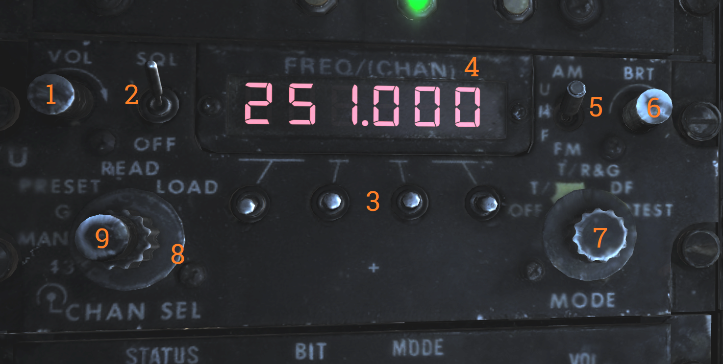 V/UHF radio 2. Radio and controls.
| No. | Control/Indicator | Function |
|---|---|---|
| 1 | VOL knob | Controls volume of V/UHF 2 audio to RIO headset. |
| 2 | SQL switch | ON/OFF switch enabling squelch. |
| 3 | Frequency select switches | Toggle switches selecting set frequency. |
| 4 | FREQ/(CHAN) display | Readout display showing selected frequency or channel. |
| 5 | UHF switch | Selector switch selecting modulation in use. Operational in the 225.000 to 399.00 MHz band. |
| 6 | BRT knob | Knob controlling display brightness. |
| 7 | MODE knob | MODE selector knob controlling V/UHF 2 radio mode. |
| 8 | Frequency mode knob | Outer dial on the knob, selects frequency mode. |
| 9 | CHAN SEL knob | Inner dial on the knob, selects preset channel to use. |
KY-28 Control Panel
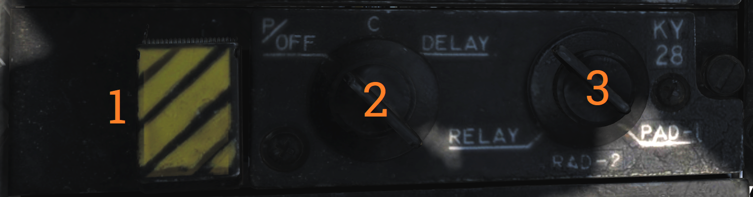
| No. | Control | Function |
|---|---|---|
| 1 | ZEROIZE switch | Switch/guard used to zeroize KY-28. |
| 2 | Power-mode switch | Switch selecting KY-28 mode of operation. |
| 3 | Radio select switch | Switch selecting which radio to use with KY-28. |
Radar Beacon Control Panel
![]() Panel controlling AN/APN-154 radar beacon.
Panel controlling AN/APN-154 radar beacon.
| No. | Control/Indicator | Function |
|---|---|---|
| 1 | MODE selector | Selector switch controlling beacon mode of operation. SINGLE - Enables beacon response to single pulse codes. DOUBLE - Enables beacon response to set double pulse code. ACLS - Enables augmentor operation for ACLS. Required for CATCC radar lockon for ACLS. |
| 2 | ACLS TEST button | Button with green light used to indicate operation or test. When pressed with MODE in ACLS illumination indicates a successful test. The light also flashes when detecting an AN/SPN-42 radar sweeping past and illuminates when that radar has locked on for ACLS guidance. |
| 3 | PWR switch | Switch controlling beacon power. PWR - Enables beacon and all replies depending on MODE selector. STBY - Used to warm up the system, also enables ACLS replies if the MODE selector is set to ACLS. OFF - Beacon off. |
Liquid Cooling Control Panel
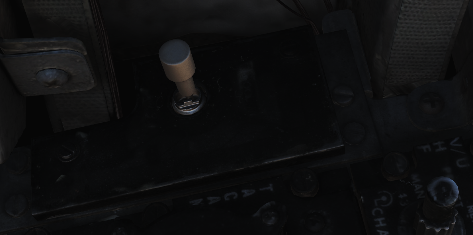 LIQ COOLING switch controlling the liquid cooling system for the AWG-9 and AIM-54. The AWG-9 circuit can be enabled independently of the AIM-54. This switch needs to be enabled for the respective system before AWG-9 operation or AIM-54 missile preparation.
ICS Control Panel
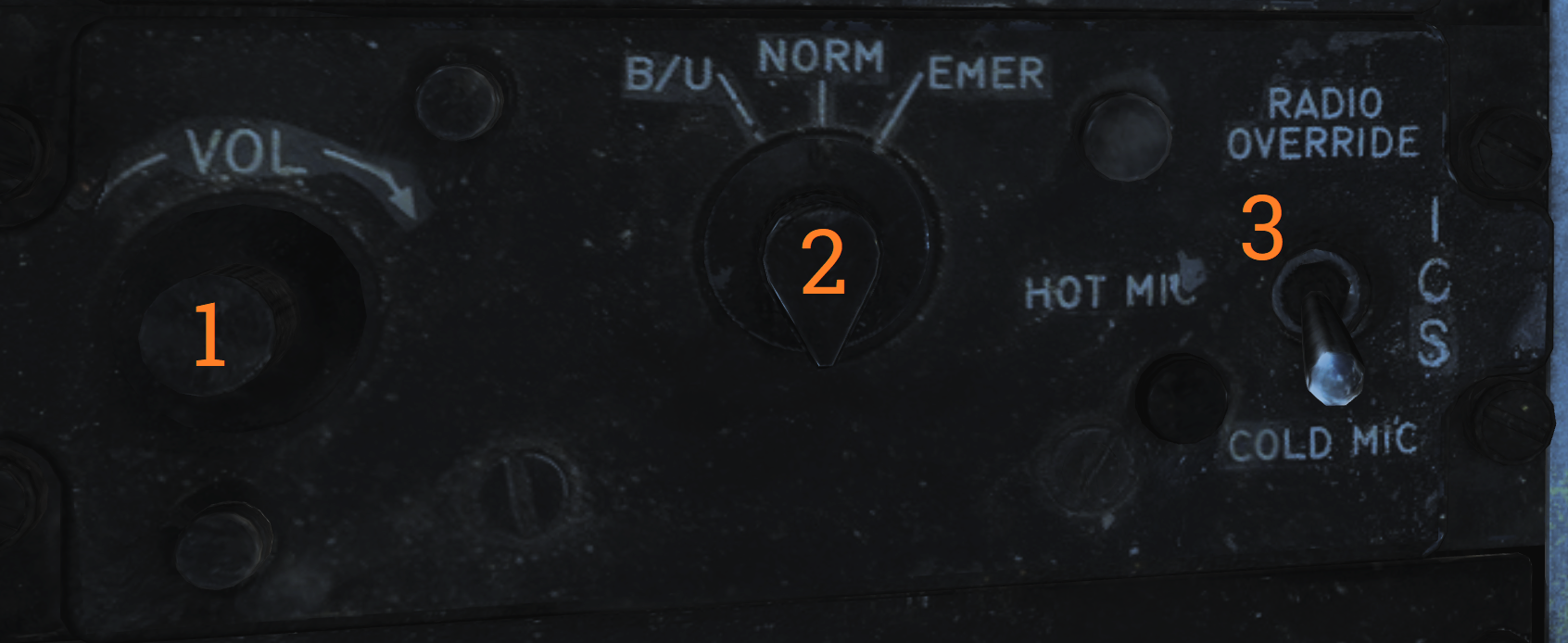 Control panel for ICS.
| No. | Control | Function |
|---|---|---|
| 1 | VOL knob | Volume control knob for intercommunication audio from the pilot to the RIO. |
| 2 | Amplifier selection knob | Knob selecting which amplifier to use for the RIO’s headset audio. |
| 3 | ICS switch | Selects ICS function. RADIO OVERRIDE - Makes ICS audio override radio audio. HOT MIC - Allows talking to the pilot without pressing the PTT. COLD MIC - Allows talking to the pilot only while the PTT is pressed. |
Eject Command Lever
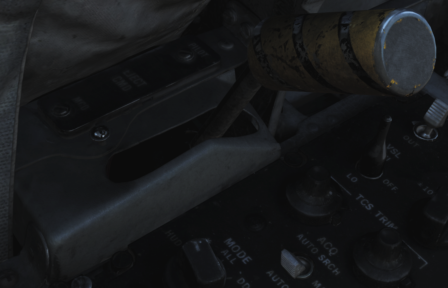 A pilot initiated ejection will always eject both crew members. The EJECT CMD lever controls what happens when the RIO ejects: In PILOT mode (lever forward), only the RIO will be ejected. In MCO mode, both pilot and RIO initiated ejection will eject both crew members.
Sensor Control Panel
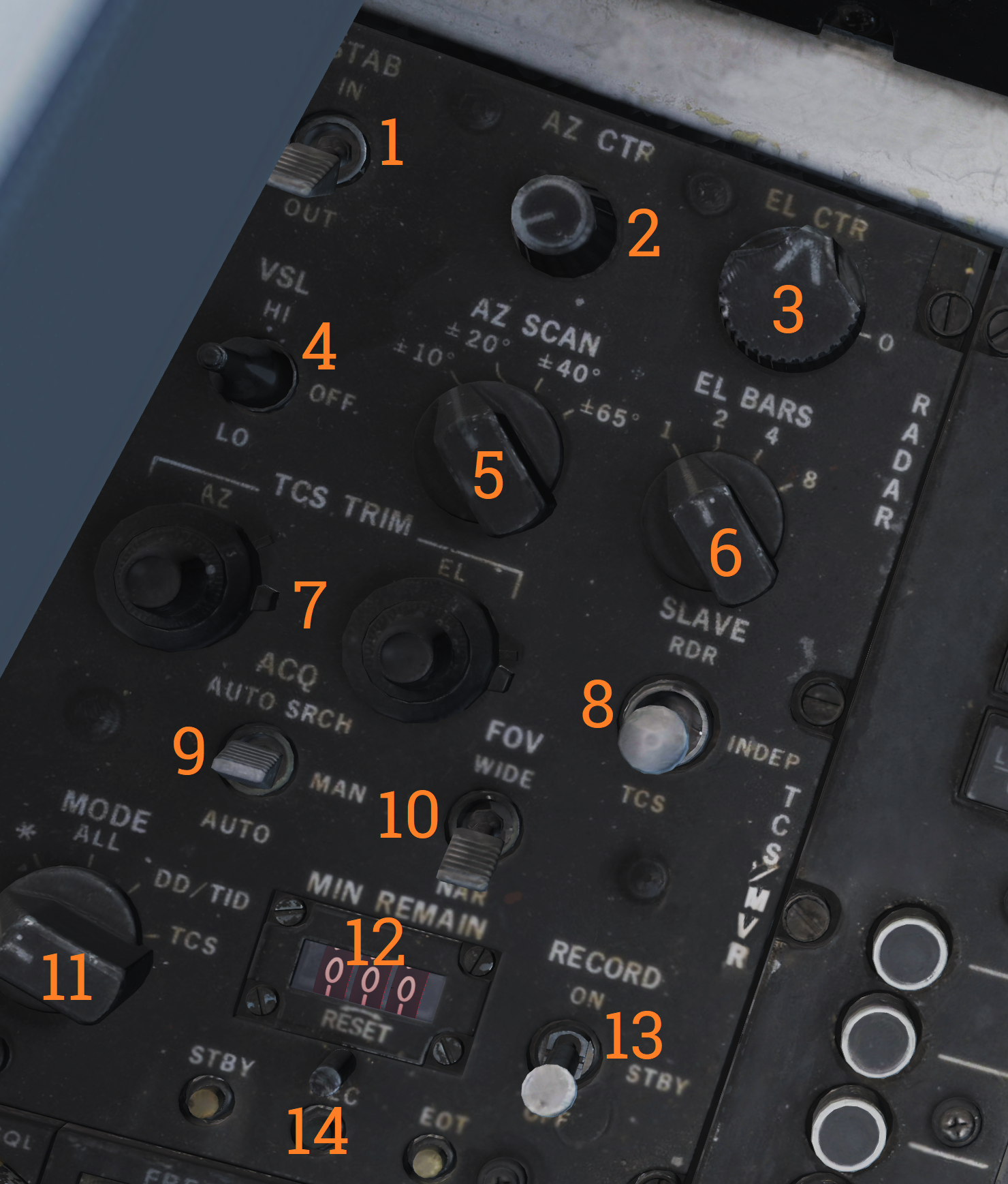 Control panel for AWG-9 scan settings, the TCS, and the airborne video tape recorder.
| No. | Control/Indicator | Function |
|---|---|---|
| 1 | STAB switch | Selector switch controlling ground stabilization of the radar. |
| 2 | AZ CTR knob | Azimuth control knob selecting the center of azimuth scan area. |
| 3 | EL CTR knob | Elevation control knob selecting the center of elevation scan area. |
| 4 | VSL switch | Selector switch spring-loaded to center which enables VSL. VSL HI or LO can be selected. |
| 5 | AZ SCAN knob | Azimuth scan knob selecting azimuth scan volume. |
| 6 | EL BARS knob | Elevation bar knob selecting the number of bars to scan in elevation. |
| 7 | TCS TRIM knobs | Trim knobs used to calibrate TCS video in azimuth and elevation. |
| 8 | SLAVE switch | Selector switch selecting which sensor is slaved to the other. |
| 9 | ACQ switch | Selector switch selecting acquisition mode for the TCS. AUTO, MAN or AUTO SRCH. |
| 10 | FOV switch | Selector switch selecting field of view for the TCS, WIDE or NAR (narrow). |
| 11 | MODE knob | Knob controlling what the AVTR records. |
| 12 | MIN REMAIN display | Counter showing minutes remaining for the AVTR. |
| 13 | RECORD switch | Selector switch controlling the AVTR. OFF/STBY/ON. |
| 14 | Indicator lights | Lights indicating AVTR operation. STBY, EOT (end of tape), and REC. |
Computer Address Panel
 The CAP is used to enter data into the WCS. The MESSAGE indicator drum and buttons work similarly to the buttons on MFDs on newer aircraft.
| No. | Control/Indicator | Function |
|---|---|---|
| 1 | CLEAR button | Button clearing current TID buffer without inserting entered data. |
| 2 | ENTER button | Button inserting current data from TID buffer into the WCS. |
| 3 | Prefix & Numerical buttons | Numerical buttons with additional prefix selection functionality. |
| 4 | MESSAGE button switches | Buttons used to select functions from the MESSAGE drum. |
| 5 | MESSAGE indicator drum | Indicator drum used to indicate currently available MESSAGE functionality. |
| 6 | PRGM RESTRT button | Button used to restart the program running in the WCS. |
| 7 | CATEGORY knob | Selector knob selecting current category in use on the MESSAGE indicator drum. |
| 8 | TUNE DSBL | Non-functional. Note: All of the buttons have indicator lights indicating operation depending on function. |
Left Vertical Console
Armament Panel
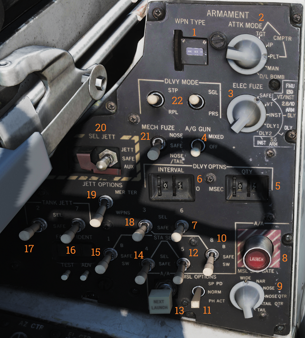 Main armament control panel in the RIO cockpit.
| No. | Control/Indicator | Function |
|---|---|---|
| 1 | WPN TYPE selector | Selector wheel selecting type of weapon used for WCS A/G calculation. |
| 2 | ATTK MODE knob | Knob selecting which A/G attack mode to use. |
| 3 | ELEC FUSE knob | Knob selecting electric fuse setting for A/G ordnance. |
| 4 | A/G GUN switch | Selector switch controlling gun mode in A/G master mode. MIXED enables the gun in addition to selected A/G ordnance. |
| 5 | QTY selectors | Selector wheels controlling quantity of A/G ordnance (including rockets) to be released. |
| 6 | INTERVAL selectors | Selector wheels controlling interval between weapons release in ripple delivery mode in milliseconds. |
| 7 | Station 6 select switch | Switch used to select station 6 for jettison or weapons A/G delivery. |
| 8 | A/A LAUNCH button | Button used for RIO launch of AIM-7 or AIM-54, hot trigger is indicated by button illumination. |
| 9 | MSL SPD GATE knob | Knob controlling the position of missile speed gate. |
| 10 | Station 8 select switch | Switch used to select station 8 for jettison or weapons A/G delivery. B selects the lower pylon for release or jettison, the SW option is non-functional. |
| 11 | MSL OPTIONS switch | Selector switch used to activate AIM-7 pulse doppler mode or AIM-54 active launch mode. |
| 12 | Station 5 select switch | Switch used to select station 5 for jettison or weapons A/G delivery. |
| 13 | NEXT LAUNCH button | Button used by RIO to select a hooked target as the next target to launch at in TWS. |
| 14 | Station 4 select switch | Switch used to select station 4 for jettison or weapons A/G delivery. |
| 15 | Station 1 select switch | Switch used to select station 1 for jettison or weapons A/G delivery. B selects the lower pylon for release or jettison, the SW option is non-functional. |
| 16 | TANK JETT station 7 switch | Switch selecting station 7 for tank jettison. |
| 17 | TANK JETT station 2 switch | Switch selecting station 2 for tank jettison. |
| 18 | Station 3 select switch | Switch used to select station 3 for jettison or weapons A/G delivery. |
| 19 | JETT OPTIONS switch | Switch selecting whether to jettison only WPNS (weapons) or MER/TER (weapon racks) in addition to weapons. Non-functional in modeled F-14. |
| 20 | SEL JETT switch | Selector switch used to jettison selected stations in normal (JETT) mode or AUX (backup) mode. The AUX position is guarded. |
| 21 | MECH FUSE switch | Selector switch used to enable and set which mechanical fuse to use for A/G ordnance. |
| 22 | DLVY MODE switches | Two selector switches used to select A/G delivery mode. One switch controls whether to release in singles or pairs and the other sets whether to release once or multiple times according to settings. |
Left Vertical Console
Left Instrument Panel
Servopneumatic Altimeter
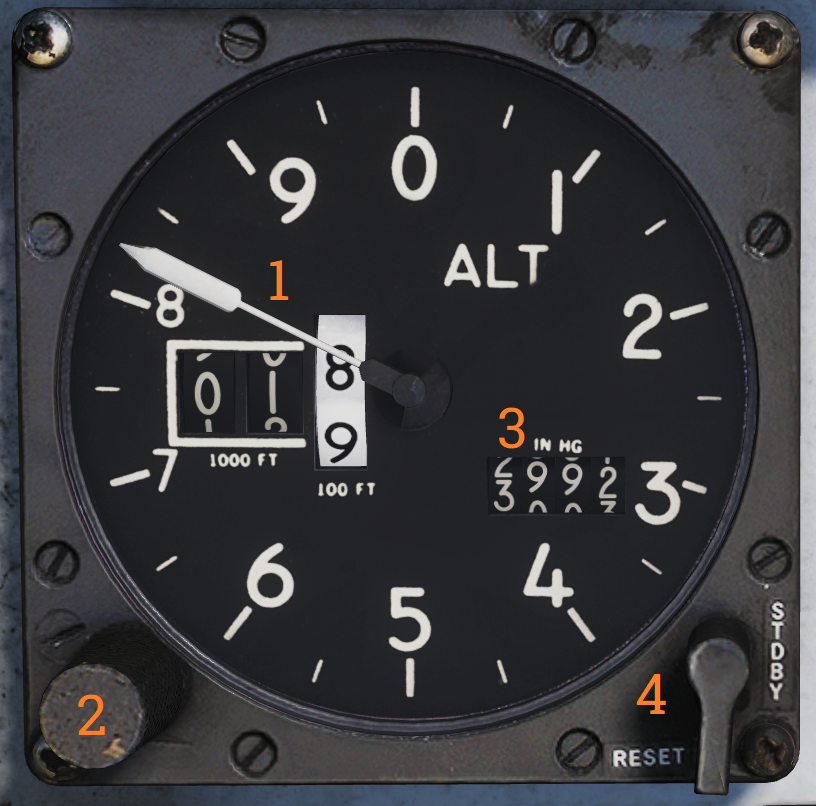 Control and indicator for the servopneumatic altimeter.
| No. | Control/Indicator | Function |
|---|---|---|
| 1 | Altimeter readout | Displays altitude digitally on three drums showing 10,000, 1,000, and 100 of feet respectively. It also displays altitude on a pointer on a circular scale indicating 100’s of feet. |
| 2 | Baroset knob | Sets local pressure in inches of mercury (in.Hg). Only used locally on the altimeter readout, all other digital indicators (via CADC) use a set 29.92 in.Hg value. |
| 3 | Local Barometric Pressure | Indicates barometric pressure setting, also called the Kollsman Window. |
| 4 | Mode switch | Three-position switch, spring-loaded to return from RESET. If power and altitude data from CADC are present, the switch can be held in RESET for 3 seconds to allow normal (servoed) mode of operation. If set to STBY or power or CADC data is absent for more than 3 seconds the system switches to backup (pressure) mode. |
| 5 | STBY flag | Red flag reading STBY that appears if the system is in backup (stand-by) mode. |
Airspeed Mach Indicator
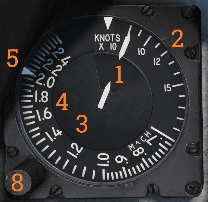 Indicated airspeed and Mach number display.
| No. | Control/Indicator | Function |
|---|---|---|
| 1 | Airspeed dial | Shows indicated airspeed on three scales, two for indicated airspeed and one moving for Mach number. |
| 2 | Indicated airspeed scale (outer) | Used to indicate indicated airspeed up to 200 knots. |
| 3 | Indicated airspeed scale (inner) | Used to indicate indicated airspeed from 200 knots to 850 knots. Covered by the airspeed dial until relevant. |
| 4 | Mach number scale | Moving scale used to indicate Mach number. Moved to show the correct Mach number relative to indicated airspeed. |
| 5 | Indicated airspeed index pointer | Can be set to the desired indicated airspeed. |
| 6 | Mach number index pointer | Can be set to the desired Mach number. Not visible in image. |
| 7 | Safe Mach number index pointer | Shows safe Mach number calculated by the CADC. Not visible in the image. |
| 8 | Index knob | Knob with a pull-out and push-in position. One sets the indexer for indicated airspeed and the other for Mach number. |
Standby Attitude Indicator
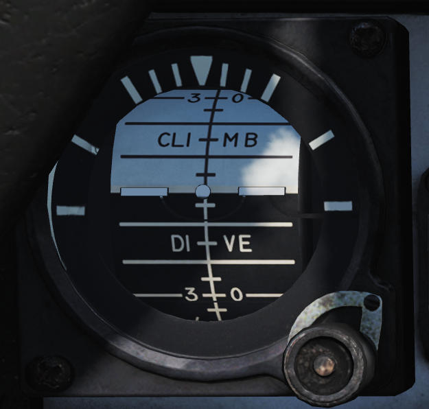 Standalone standby attitude indicator.
An OFF flag is visible on the left side when caged or when unpowered.
The knob below and to the right of the indicator cages/uncages the indicator and allows trim to correct pitch. In the pulled-out position, the indicator is caged. When pushed in, uncages the indicator and allows pitch trim by turning the knob.
UHF Remote Indicator
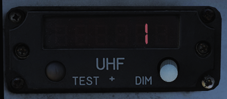 Remote indicator displaying set frequency or channel on UHF 1 (AN/ARC-159).
| No. | Control/Indicator | Function |
|---|---|---|
| 1 | UHF 1 remote channel/frequency indicator | Displays a readout of the frequency or channel set for the UHF 1 radio. |
| 2 | TEST | Initiates a test for the indicator, no fault resulting in 888.888 readout. |
| 3 | DIM | Controls display brightness. |
Center Panel
Chaff/Flare Dispense Switches
 Two switch hats on the center RIO handhold used to initiate the release of countermeasures. The switches are mirrored in regards to functionality.
| No. | Control | Function |
|---|---|---|
| 1 | Up | Initiates a single chaff release. |
| 2 | Down | Initiates set chaff release program. |
| 3 | Inboard | Initiates set jammer release program. |
| 4 | Outboard | Initiates set flare release program. |
Detail Data Display Panel
 Main radar control panel.
| No. | Control/Indicator | Function |
|---|---|---|
| 1 | TGTS switch | Switch selecting target size for missile launch zones, WCS track calculations as well as missile ATC calculation. |
| 2 | MLC switch | Switch selecting MLC mode of operation. |
| 3 | AGC switch | Switch controlling AGC speed. Currently non-functional in DCS. |
| 4 | PARAMP switch | Switch controlling the parametric amplification. Currently non-functional in DCS. |
| 5 | PULSE VIDEO knob | Knob controlling video strength of pulse video on the DDD. No effect on pulse doppler video. |
| 6 | Radar track indicator lights | Indicator lights indicating radar tracking in the STT modes. ANT TRK - Indicates the radar is tracking the target’s angle. RDROT - Indicates the target is within the range or rate gate and being tracked. JAT - Indicates the radar is tracking a jamming source’s angle. IROT - Indication of TCS angle tracking, called IROT as this was originally used for the IRST in the early -A. |
| 7 | RANGE display | Rotary drum indicator displaying the currently selected radar range. Can also be blank if no range scale is used on the DDD. |
| 8 | RANGE buttons | Buttons used to select radar range. |
| 9 | BRIGHT knob | Knob used to control the brightness of the DDD by means of a polarized filter in front of the DDD. |
| 10 | IR AUDIO THRLD knob | Knob used to control IR AUDIO threshold, non-functional with TCS. |
| 11 | IR AUDIO VOL knob | Knob used to control IR AUDIO volume, non-functional with TCS. |
| 12 | IR GAIN knob | Knob used to control IR GAIN, non-functional with TCS. |
| 13 | XMTR CHAN wheel | 12-position wheel used to control AWG-9 operating frequency. Currently non-functional in DCS. |
| 14 | MSL CHAN wheel | 6-position wheel used to control missile channel used by AIM-7 or AIM-54. Currently non-functional in DCS. |
| 15 | DISPLAY buttons | Buttons used to control what to display on the DDD. IR button non-functional with TCS. |
| 16 | WCS MODE buttons | Buttons used to select the current AWG-9 operating mode. |
| 17 | WCS MODE display | Rotary drum indicator displaying current WCS mode. |
| 18 | Vc switch | Switch used to select different closing velocity scales on the DDD in PD modes. |
| 19 | ERASE knob | Knob used to control the intensity of the ERASE beam on the DDD, controlling how quickly the image on the DDD fades. |
| 20 | PULSE GAIN knob | Knob used to control the gain of the AWG-9 in pulse mode, normally left in detent unless needed because of clutter or jamming. |
| 21 | ASPECT switch | Switch used to control the rate region covered by the doppler filters in pulse doppler modes and if to use edge or centroid tracking in pulse mode. These settings correspond to expected target aspect. |
| 22 | EL indicator | Meter with indicator needles indicating sensor elevation. Left indicator shows current actual radar antenna elevation. The right indicates commanded radar elevation while RDR is selected on HCU and TCS elevation while IR/TV is selected. |
| 23 | CCM MODES buttons | Buttons used to set AWG-9 functionality countering jamming targets. Currently non-functional in DCS. |
| 24 | JAM/JET knob | Control knob used to set the threshold at which a radar return is considered a jamming target. Currently non-functional in DCS. |
| 25 | ACM THRLD knob | Control knob used to control radar sensitivity level at close ranges. Usually set automatically with the knob in the detent position. |
| 26 | PD THRLD knobs | Control knobs used to set pulse doppler video threshold in the CLEAR (upper half of DDD) region and in the CLUTTER (lower half of the DDD) region. |
| 27 | DDD radar display | Main AWG-9 radar display. |
Center Console
Tactical Information Display (TID)
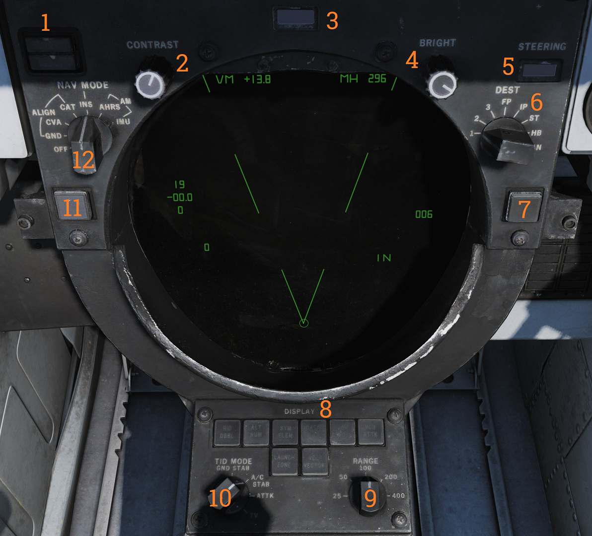 Tactical information display and corresponding and navigational controls.
| No. | Control/Indicator | Function |
|---|---|---|
| 1 | INS status indicator | Indicator light showing the status of the INS during alignment. STBY indicates power applied but not aligned. READY indicates minimum launch criteria for AIM-54. Both lights turn off when INS mode is selected. Can otherwise indicate faults. |
| 2 | CONTRAST knob | Control knob that controls the contrast of TCS video. |
| 3 | DATA READOUT drum | Readout drum indicating the source of the data displayed on the TID readouts. Might be blank for sources not having their own text on the drum. |
| 4 | BRIGHT knob | Control knob controlling TID brightness. |
| 5 | STEERING indicator drum | Readout drum indicating current steering information being displayed to the pilot. |
| 6 | DEST selector | Selector knob controlling what destination to use for the navigation destination mode. |
| 7 | CLSN button | Button with indication used to select collision steering towards a tracked target or TWS centroid. |
| 8 | DISPLAY buttons | Buttons controlling what elements are shown on the TID. Contains indicator lights showing selection. |
| 9 | RANGE selector | Selector switch selecting the current scale of the TID. Corresponds to the distance the diameter represents. |
| 10 | TID MODE selector | Selector switch controlling current TID presentation. |
| 11 | TRACK HOLD button | Button extending the amount of time before a track is dropped after the last radar observation to two minutes. Normal time is 14 seconds. |
| 12 | NAV MODE selector | Selector switch controlling navigation reference systems. Controls which system is in use and also alignment of the INS. |
Hand Control Unit (HCU)
 Main radar and TCS control stick.
| No. | Control/Indicator | Function |
|---|---|---|
| 1 | IR/TV switch | Switch controlling TCS power. Enables selection of OFF/STBY and ON. |
| 2 | IR/TV overtemp indicator | Light indicating the presence of an overtemperature condition in the TCS. |
| 3 | LIGHT TEST button | Button allowing a test of all AWG-9 lights. |
| 4 | PWR RESET indicator | Light indicating one or more inoperative secondary power supplies. |
| 5 | PWR RESET button | Button allowing a reset of inoperative secondary power supplies. If the condition triggering the inoperational state remains the affected supplies will remain inoperational. |
| 6 | WCS indicator | Light indicating selection of STBY or XMT with the radar not yet timed out or selection of XMT with radar transmission remaining off. |
| 7 | WCS switch | Switch controlling WCS power (computer and radar). STBY turns on power to the WCS and begins radar warmup without transmission. XMT enables radar transmission if the radar is ready. Display warmup time is 30 seconds, radar warmup is 3 minutes. |
| 8 | MRL button | Button selecting manual rapid lockon mode. Overrides all operational modes except PLM and VSL. |
| 9 | OFFSET button | Button used to offset TID to hooked location on the display. |
| 10 | ELEV thumbwheel | Thumbwheel used to fine-tune elevation of the radar antenna for STT lockon acquisition. |
| 11 | HCU trigger | Used to select and trigger different functions in the WCS depending on current mode and HCU function. First detent is HALF ACTION, second detent is FULL ACTION. Examples of use are target acquisition and symbol hook. |
| 12 | Hand control function buttons | Buttons with an indication used to control the function of the HCU stick. Mutually exclusive. IR/TV - Selects control of TCS azimuth, elevation, and tracking. Enables display of TCS elevation on the right elevation indicator on DDD. RDR - Selects control of radar antenna for STT lock-on and return to search if already in STT. Enables display of currently commanded radar antenna elevation on the right elevation indicator on DDD. DDD CURSOR - Selects control of DDD cursor used to mark a geographical position while in pulse radar mode. TID CURSOR - Selects control of TID cursor used to hook (select) symbols on the TID. |
Center Console
Tactical Information Display (TID)
Tactical information display and corresponding and navigational controls.
| No. | Control/Indicator | Function |
|---|---|---|
| 1 | INS status indicator | Indicator light showing the status of the INS during alignment. STBY indicates power applied but not aligned. READY indicates minimum launch criteria for AIM-54. Both lights turn off when INS mode is selected. Can otherwise indicate faults. |
| 2 | CONTRAST knob | Control knob that controls the contrast of TCS video. |
| 3 | DATA READOUT drum | Readout drum indicating the source of the data displayed on the TID readouts. Might be blank for sources not having their own text on the drum. |
| 4 | BRIGHT knob | Control knob controlling TID brightness. |
| 5 | STEERING indicator drum | Readout drum indicating current steering information being displayed to the pilot. |
| 6 | DEST selector | Selector knob controlling what destination to use for the navigation destination mode. |
| 7 | CLSN button | Button with indication used to select collision steering towards a tracked target or TWS centroid. |
| 8 | DISPLAY buttons | Buttons controlling what elements are shown on the TID. Contains indicator lights showing selection. |
| 9 | RANGE selector | Selector switch selecting the current scale of the TID. Corresponds to the distance the diameter represents. |
| 10 | TID MODE selector | Selector switch controlling current TID presentation. |
| 11 | TRACK HOLD button | Button extending the amount of time before a track is dropped after the last radar observation to two minutes. Normal time is 14 seconds. |
| 12 | NAV MODE selector | Selector switch controlling navigation reference systems. Controls which system is in use and also alignment of the INS. |
Hand Control Unit (HCU)
Main radar and TCS control stick.
| No. | Control/Indicator | Function |
|---|---|---|
| 1 | IR/TV switch | Switch controlling TCS power. Enables selection of OFF/STBY and ON. |
| 2 | IR/TV overtemp indicator | Light indicating the presence of an overtemperature condition in the TCS. |
| 3 | LIGHT TEST button | Button allowing a test of all AWG-9 lights. |
| 4 | PWR RESET indicator | Light indicating one or more inoperative secondary power supplies. |
| 5 | PWR RESET button | Button allowing a reset of inoperative secondary power supplies. If the condition triggering the inoperational state remains the affected supplies will remain inoperational. |
| 6 | WCS indicator | Light indicating selection of STBY or XMT with the radar not yet timed out or selection of XMT with radar transmission remaining off. |
| 7 | WCS switch | Switch controlling WCS power (computer and radar). STBY turns on power to the WCS and begins radar warmup without transmission. XMT enables radar transmission if the radar is ready. Display warmup time is 30 seconds, radar warmup is 3 minutes. |
| 8 | MRL button | Button selecting manual rapid lockon mode. Overrides all operational modes except PLM and VSL. |
| 9 | OFFSET button | Button used to offset TID to hooked location on the display. |
| 10 | ELEV thumbwheel | Thumbwheel used to fine-tune elevation of the radar antenna for STT lockon acquisition. |
| 11 | HCU trigger | Used to select and trigger different functions in the WCS depending on current mode and HCU function. First detent is HALF ACTION, second detent is FULL ACTION. Examples of use are target acquisition and symbol hook. |
| 12 | Hand control function buttons | Buttons with an indication used to control the function of the HCU stick. Mutually exclusive. IR/TV - Selects control of TCS azimuth, elevation, and tracking. Enables display of TCS elevation on the right elevation indicator on DDD. RDR - Selects control of radar antenna for STT lock-on and return to search if already in STT. Enables display of currently commanded radar antenna elevation on the right elevation indicator on DDD. DDD CURSOR - Selects control of DDD cursor used to mark a geographical position while in pulse radar mode. TID CURSOR - Selects control of TID cursor used to hook (select) symbols on the TID. |
Left and Right Footwells
ICS Foot Button
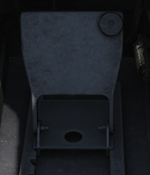 RIO left footrest containing ICS PTT for COLD MIC intercommunication.
Mic Foot Button
 RIO right footrest containing PTT for transmission on UHF 1, V/UHF 2, or both depending on ICS setting.
Right Instrument Panel
Clock
 Mechanical wind-up clock.
The knob on the lower left corner is used to wind up the clock by turning it clockwise and pulling it out and turning it to set the hour and minute hands.
The control on the upper right corner is used to start, stop, and reset a 1-hour elapsed time counter.
ALR-67 Indicator
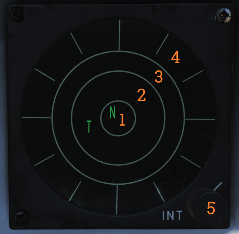 Indicator showing emitters detected by the ALR-67 RWR (radar warning receiver) set.
| No. | Control/Indicator | Function |
|---|---|---|
| 1 | System status circle, area I | Upper left quadrant of 1. Shows symbol indicating the type of threats selected to be shown. N - Normal priority I - AI, airborne interceptors prioritized. A - AAA, anti-air artillery prioritized. U - Unknown emitters prioritized. F - Friendly emitters shown in addition to other threats. |
| 2 | System status circle, area II | Upper right quadrant of 1. Indicates if limited mode is selected. (Blank) - Limited mode not selected. L - Limited mode selected, display shows only 6 highest prioritized threats. |
| 3 | System status circle, area III | Lower half of 1. Displays failure codes and if offset display is selected. (Blank) - No failure detected and offset not selected. B - BIT failure. T - Thermal overload. O - Offset display selected. Threats will be separated to allow readout of overlapping symbols. Bearing accuracy degraded for displaced threats. |
| 4 | Non-lethal band | Displays emitters not a direct threat to own aircraft, either because deemed out of range or lacking weaponry to do so. |
| 5 | Lethal band | Displays threats that are deemed within range and capable of engaging own aircraft but not currently doing so. |
| 6 | Critical band | Displays direct threats to own aircraft. Systems capable of engaging own aircraft and showing current intent of doing so. |
| 7 | INT knob | Intensity/brightness knob. Controls the brightness of the display. |
Fuel Quantity Totalizer
 Total fuel quantity readout, shows total fuel quantity in all aircraft tanks.
Threat Advisory and Master Caution Lights
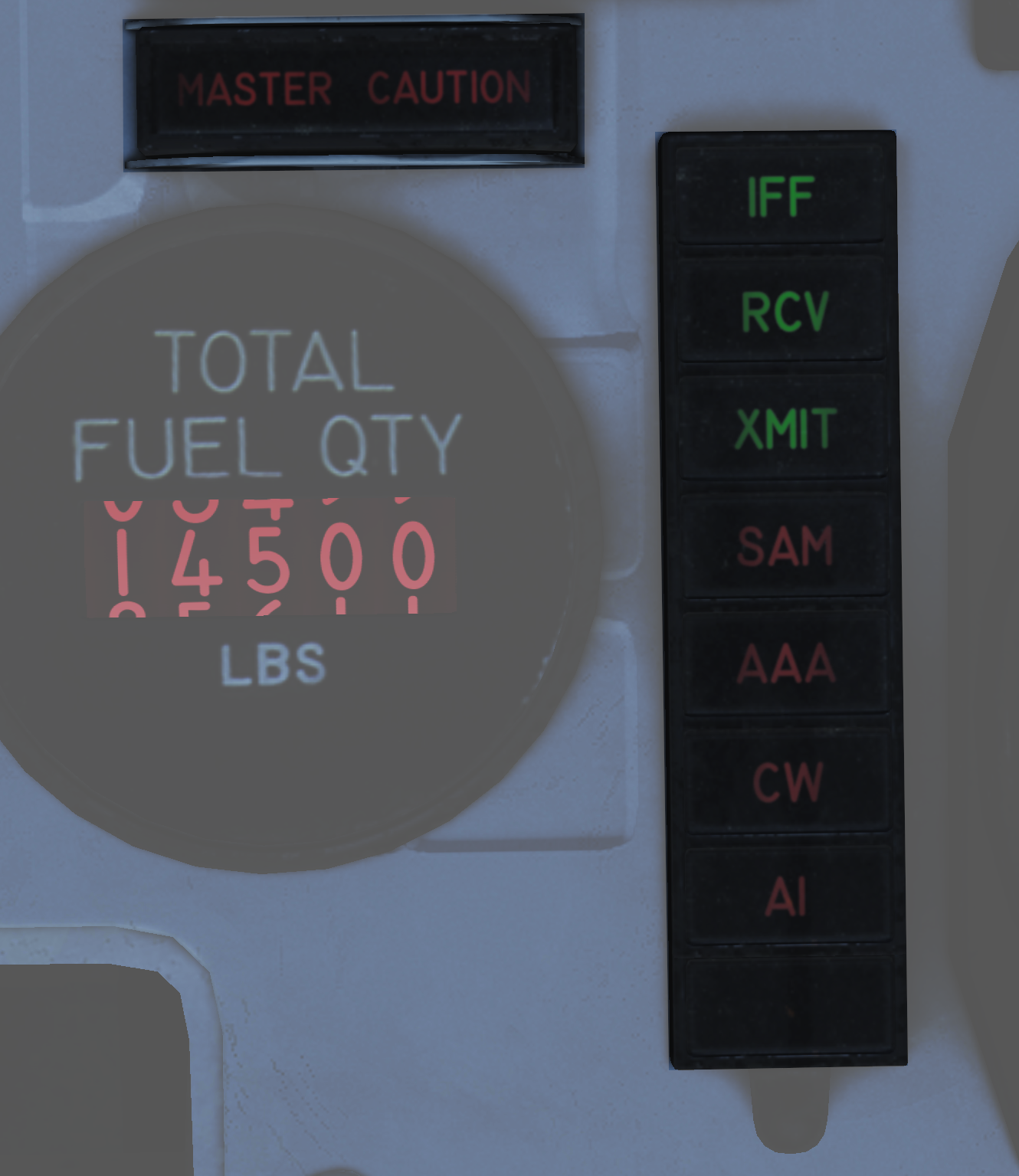
| No. | Indicator | Function |
|---|---|---|
| 1 | MASTER CAUTION light and button | Flashes to indicate status change on the RIO caution/advisory panel. Press to reset and turn off light until the next event. |
| 2 | IFF | Advisory light indicating received mode 4 interrogation without own system generating a reply. |
| 3 | RCV | Advisory light indicating ALQ-126 is receiving a threat identification signal. |
| 4 | XMIT | Advisory light indicating ALQ-126 is transmitting. |
| 5 | SAM | Warning light, steady illumination when detecting lockon from a SAM tracking radar. Flashes when a missile launch is detected. |
| 6 | AAA | Warning light, steady illumination when detecting lockon from a AAA tracking radar. Flashes when AAA engagement is detected. |
| 7 | CW | Warning light indicating detection of a continuous wave emitter. |
| 8 | AI | Warning light, steady illumination when detecting lockon from an airborne interceptor radar. |
Bearing Distance Heading Indicator (BDHI)
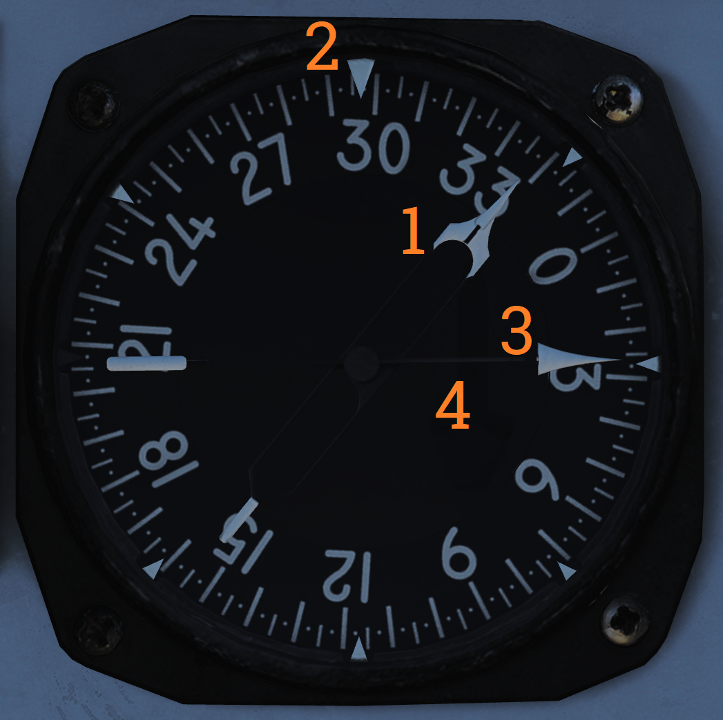 Display indicating azimuth and bearing information.
| No. | Indicator | Function |
|---|---|---|
| 1 | No. 2 bearing pointer | Indicates magnetic course to tuned TACAN station. |
| 2 | Compass rose | Shows current aircraft magnetic heading. |
| 3 | No. 1 bearing pointer | Indicates bearing to tuned UHF/ADF station. |
| 4 | Distance counter | Indicates slant range to tuned TACAN station in nautical miles. (Not visible in this image.) |
Canopy Jettison Handle
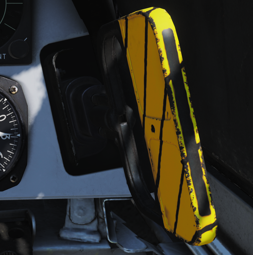 Handle used to manually jettison canopy.
Right Knee Panel
Caution-Advisory Panel
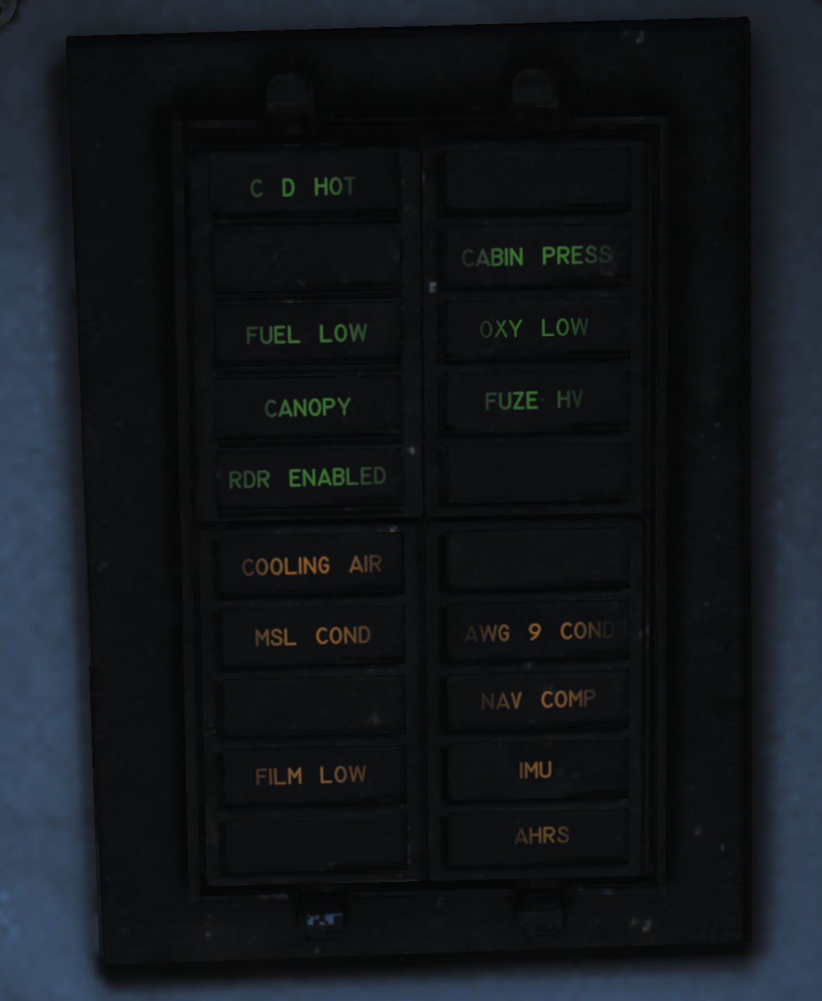
| No. | Indicator | Function |
|---|---|---|
| 1 | C&D HOT | Caution light indicating overheat in RIO controls and displays. |
| 2 | CABIN PRESS | Caution light indicating cabin pressure is too low. |
| 3 | FUEL LOW | Caution light indicating fuel below 1,000 pounds in either aft and left or forward and right fuel feed groups. |
| 4 | OXY LOW | Caution light indicating oxygen quantity is below 2 liters or pressure too low. |
| 5 | CANOPY | Caution light indicating canopy not down and locked. |
| 6 | FUSE HV | Caution light indicating AWW-4 electric fuse inoperative. |
| 7 | RDR ENABLED | Caution light indicating that radar operation with weight on wheels is possible. |
| 8 | COOLING AIR | Advisory light indicating overtemperature condition in the electronic forced air cooling system. |
| 9 | MSL COND | Advisory light indicating overtemperature or underpressure in missile coolant flow, either of which shuts down the missile coolant pump. Can also indicate that the LIQ COOLING switch is not in the AWG-9/AIM-54 position with the WCS in STBY or ON when the Phoenix fairings are installed. |
| 10 | AWG-9 COND | Advisory light indicating overheat or overpressure in the AWG-9 coolant flow or that the overtemperature switch has shut down the coolant pump. |
| 11 | NAV COMP | Advisory light indicating failure in the INS or CSDC with the NAV MODE switch in INS. |
| 12 | FILM LOW | Advisory light indicating low remaining quantity of mission recorder film. |
| 13 | IMU | Advisory light indicating a failure in the inertial measuring unit or that the navigation system is in AHRS/AM mode. |
| 14 | AHRS | Advisory light indicating that the attitude or heading information from the AHRS is unreliable. |
Right Vertical Console
Electronic Countermeasures Display (ECMD)
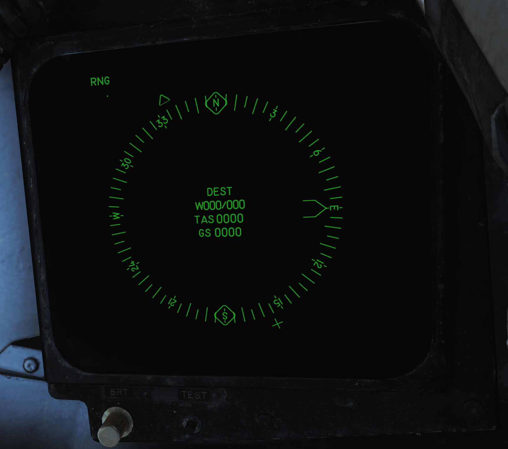 Display used for navigational information and AN/ALR-45 ECM (only in F-14A with AN/ALR-45). Has a brightness control knob, test button and a BIT indicator showing the status of the display (solid black when operational, showing white flags when indicating a fail condition).
Right Side Console
Radar Warning Receiver Panel
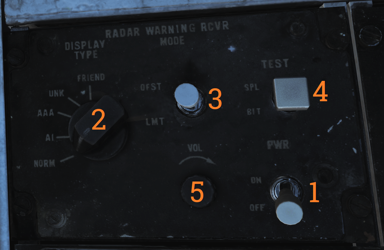
| No. | Control | Function |
|---|---|---|
| 1 | PWR switch | Switch controlling power to the ALR-67. |
| 2 | DISPLAY TYPE selector | Selector switch controlling what type of threats to prioritize and display. |
| 3 | MODE switch | Switch spring-loaded to center (OFF) position. Can be held to OFST (offset) and LMT (limit) position to enable respective function while held. |
| 4 | TEST switch | Switch spring-loaded to center. Momentary selection of BIT indicates BIT in ALR-67. Selection of SPL (special) while BIT page 1 is displayed shows the special BIT status page while held and then for 3 seconds when released. |
| 5 | VOL knob | Volume knob controlling ALR-67 audio to RIO. |
Digital Data Indicator (DDI)
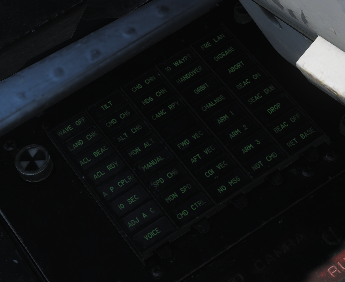 Digital data indicator used to display commands received via the data link.
| No. | Indicator | Function |
|---|---|---|
| 1 | AFT VEC | Aircraft is being vectored to approach target from the rear hemisphere. |
| 2 | COL VEC | Aircraft is being vectored on a collision course to target. |
| 3 | NO MSG | No message at this time, indicates presence of data link communication while not receiving a command. |
| 4 | TO WAY PT | Proceed to the point being indicated by target information. |
| 5 | HANDOVER | TDS is handing own aircraft over to another control center. |
| 6 | ORBIT | Assume orbit at present position maintaining maximum endurance. |
| 7 | CHALNGE | Intercept and visually identify the target. |
| 8 | ARM 1 | Intercept and destroy the indicated hostile target using AIM-54. |
| 9 | ARM 2 | Intercept and destroy the indicated hostile target using AIM-7. |
| 10 | ARM 3 | Intercept and destroy the indicated hostile target using AIM-9. |
| 11 | NOT CMD | Ignore currently received heading, speed, and altitude. Also means valid command BIT not yet available. |
| 12 | FRE LAN | Free to attack the most suitable target. |
| 13 | DIS’GAGE | Cease fire. |
| 14 | ABORT | Abort action. |
| 15 | BEAC ON | Enable APN-154 tracking beacon. |
| 16 | BEAC DUB | Set APN-154 to double-pulse mode. |
| 17 | DROP | Command to release a weapon in data link A/G attack, manually or automatically if in data link attack mode. |
| 18 | BEAC OFF | Turn off APN-154 tracking beacon. |
| 19 | RET BASE | Return to the indicated home base. |
| 20 | WAVE OFF | Wave off, automatic AFCS disengagement. |
| 21 | LAND CHECK | CATCC has a data link channel available for AFCS, complete landing checklist. |
| 22 | ACL BEAC | Directed by carrier to enable APN-154 beacon. |
| 23 | ACL RDY | ACL has locked onto aircraft APN-154 beacon and is transmitting zero pitch and bank signals. Glideslope information is now available to the pilot. |
| 24 | A/P CPLR | ACL is ready to take control of the aircraft for the ACL approach, autopilot should be engaged. |
| 25 | 10 SEC | Indicates 10 seconds to the next action or waypoint. In ACL indicates that the ship's motion is taken into account for ACL. |
| 26 | ADJ A/C | Indication from the control station of another aircraft near own aircraft. |
| 27 | VOICE | Indicates ACL not available, switch to voice procedures. |
| 28 | TILT | Indicates no data link message received in the last 10 seconds. In ACL indicates no messages in the last 2 seconds, will disengage AFCS. |
| 29 | CMD CHG | Indicates imminent or recently changed command instructions. |
| 30 | ALT CHG | Indicates imminent or recently changed altitude command. |
| 31 | MON ALT | Message indicating altitude command not being followed with enough precision. |
| 32 | MANUAL | Indicates autopilot should not be engaged. |
| 33 | SPD CHG | Indicates imminent or recently changed speed command. |
| 34 | MON SPD | Message indicating speed command not being followed with enough precision. |
| 35 | CMD CTRL | Indicates aircraft under data link control for landing. |
| 36 | CHG CHN | Command to change data link channel. |
| 37 | HDG CHN | Indicates imminent or recently changed heading command. |
| 38 | CANC RPY | TDS has canceled reply messages. |
| 39 | FWD VEC | Aircraft is being vectored to approach the target from the front hemisphere. |
DECM Control Panel
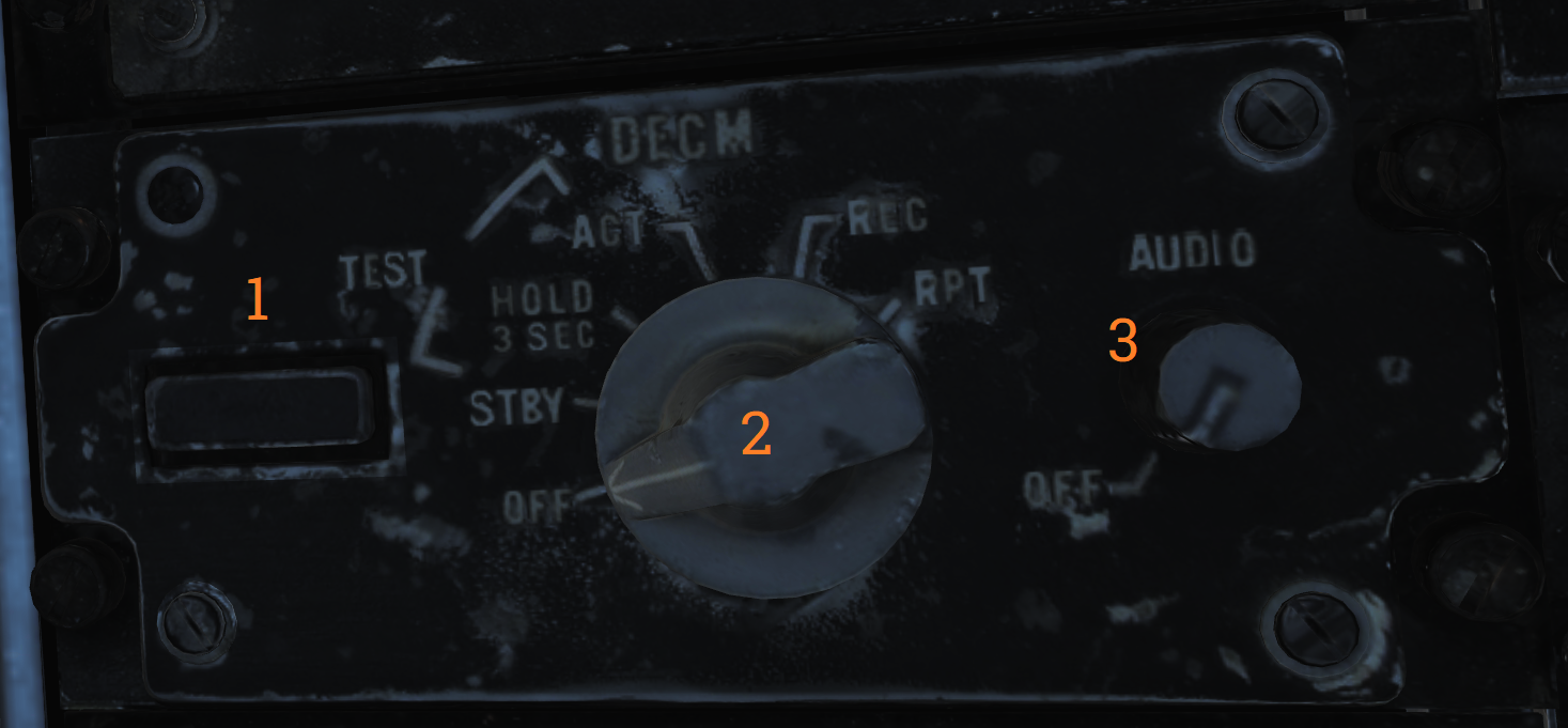 Control panel for the DECM jammer (AN/ALQ-126).
| No. | Control/Indicator | Function |
|---|---|---|
| 1 | STANDBY light | Orange light indicating warm-up when the system is placed in STBY. Goes out after complete warm-up. Indication during test or operation indicates a fault has occurred. |
| 2 | DECM selector | DECM power/mode switch. Used to control power and function of DECM. OFF - Turns off power to AN/ALQ-126. STBY - Standby, applies power to warm-up system. TEST/HOLD 3 SEC - Should be held in this position for 3 seconds to prepare for system test. TEST/ACT - Starts AN/ALQ-126 BIT, used after 3 seconds in TEST/HOLD 3 SEC position. REC - Receive, enables AN/ALQ-126 to receive and analyze threat signals. Detected missile launch may force the system into repeat mode. RPT - Repeat, enables AN/ALQ-126 to use programmed responses to received threat signals. |
| 3 | AUDIO knob | Volume knob, sets audio volume from AN/ALQ-126 to RIO headset. |
Data Link Control Panel
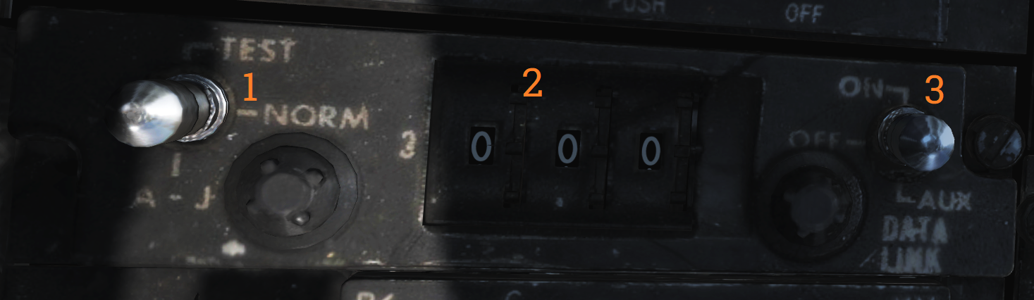 Control panel for the data link.
| No. | Control | Function |
|---|---|---|
| 1 | Transmission mode switch | Sets data link transmission mode. TEST - Starts system test. NORM - Normal operational mode. A/J - Anti-jam mode. |
| 2 | Frequency select wheels | Thumbwheels used to set data link frequency. |
| 3 | Data link power switch | Enables power to data link, also used to set AUX (auxiliary) mode. |
Data Link Reply and Antenna Control Panel
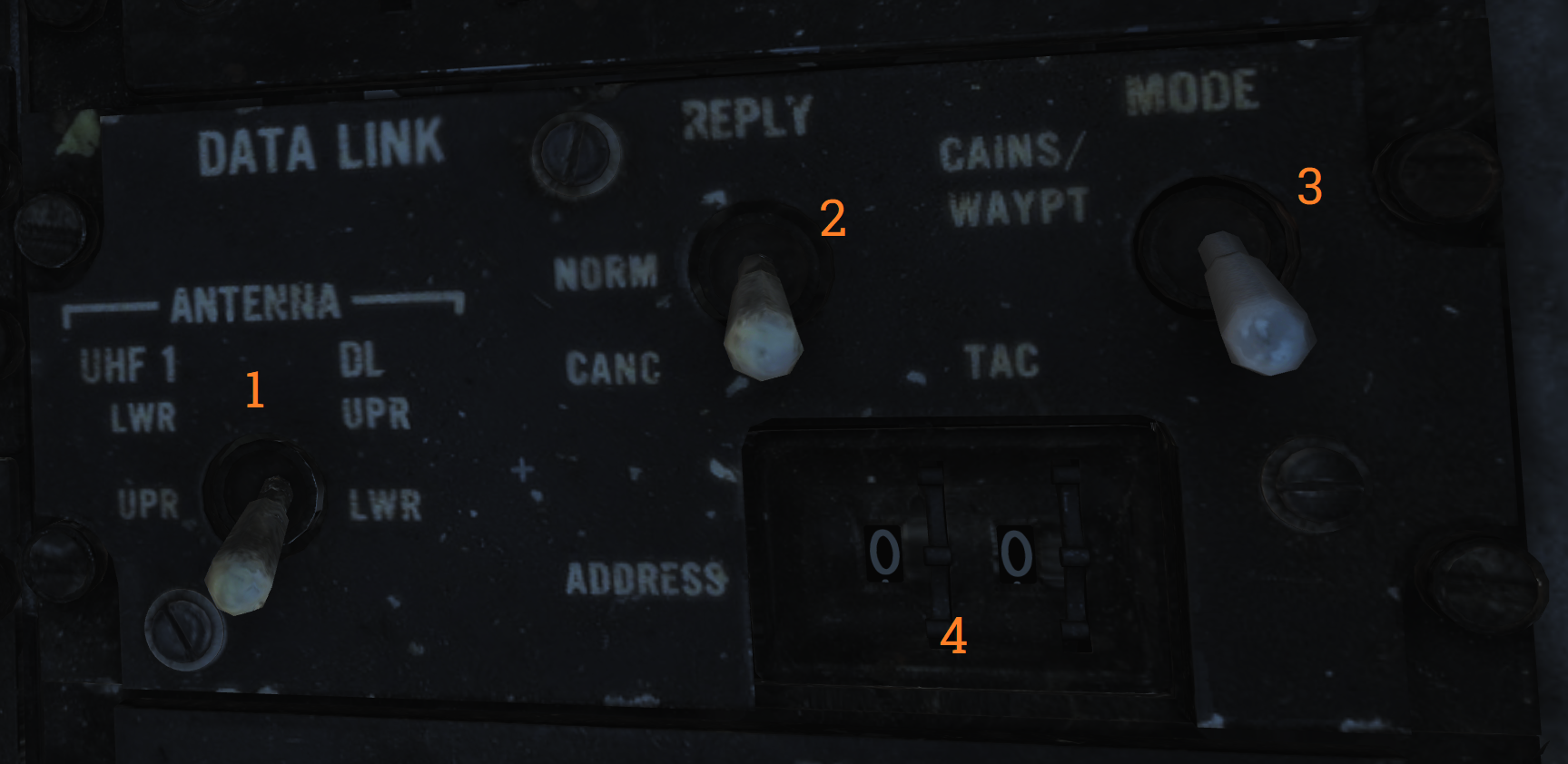 Panel used to control data link alignment, reply, and antenna.
| No. | Control | Function |
|---|---|---|
| 1 | ANTENNA switch | Switch selecting antenna in use for UHF 1 and data link. |
| 2 | REPLY switch | Used to transmit data link reply, transmits in NORM (normal), disabled in CANC (cancelled). |
| 3 | MODE switch | Switch spring-loaded to TAC but held by solenoid. Enables data link alignment and waypoint update. CAINS/WAYPT - Enables data link alignment and waypoint update. TAC - Enables manual selection of frequencies, stops data link alignment. |
| 4 | ADDRESS thumbwheel | Sets what data link address own aircraft uses. (Sets two least significant digits, others set by ground crew.) |
AN/ALE-39 Control Panel
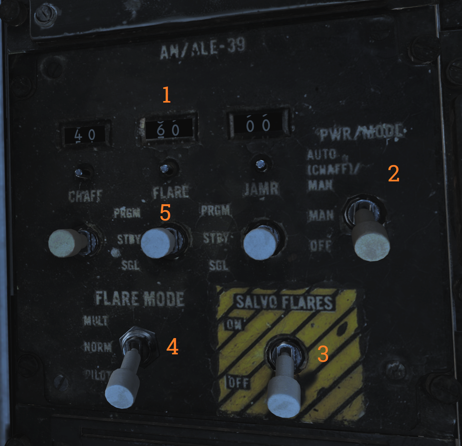
| No. | Control/Indicator | Function |
|---|---|---|
| 1 | Inventory counters | Analog counters used to indicate remaining quantities of loaded countermeasures. Are manually set by pushing in and rotating the knob below each counter. |
| 2 | PWR/MODE switch | Switch enabling power and selecting the operational mode of the AN/ALE-39. AUTO(CHAFF)/MAN - Allows manual release of countermeasures and automatic release of chaff by threat detection in the ECM systems. MAN - Allows manual release of countermeasures. OFF - Disables AN/ALE-39. |
| 3 | SALVO FLARES switch | Enables parallel rapid firing of all flares. Switch needs to be lifted to move to the ON position. |
| 4 | FLARE MODE switch | Switch selecting operational mode for launching flares. Also controls what countermeasure the DLC button on the pilot stick ejects while airborne. MULT - Multiple, each flare ejection command will eject one flare from each launcher subsection loaded with flares. Affects both manual and programmed releases. NORM - Normal, each flare ejection command will eject one flare in total. Affects both manual and programmed releases. PILOT - Enables the pilot to manually release flares with the pilot stick DLC button, the other positions release chaff with DLC button depression. |
| 5 | Countermeasure release switches | Switches spring-loaded to center which controls respective countermeasure release actuation. PRGM - Program, switch needs to be lifted to enter this position, momentary actuation initiates programmed release. STBY - No release. SGL - Single, momentary actuation releases a single countermeasure. |
AA1 Control Panel
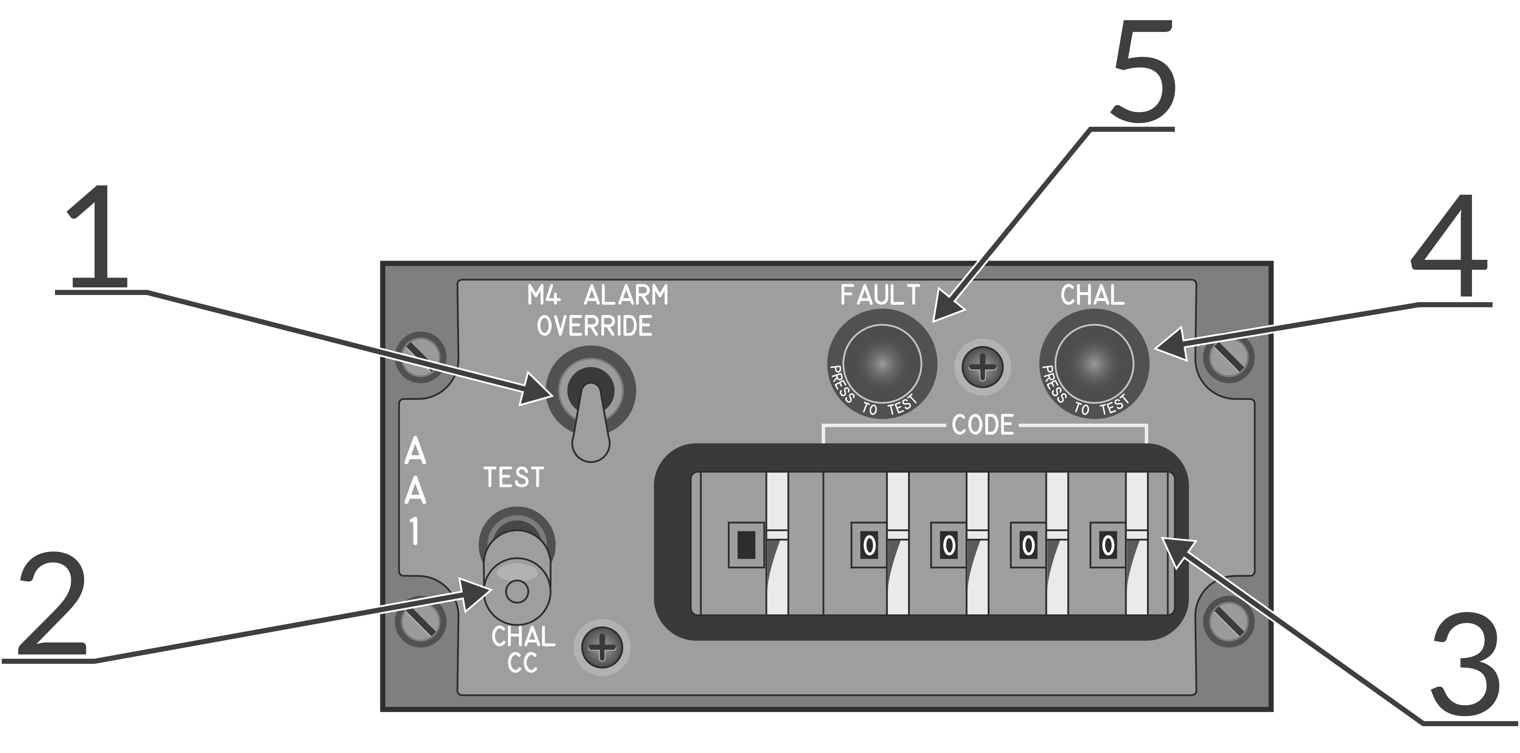 AN/APX-76 interrogator control panel.
| No. | Control/Indicator | Function |
|---|---|---|
| 1 | M4 ALARM OVERRIDE switch | Switch disabling the mode 4 tone alarm in the RIO headset. |
| 2 | TEST-CHAL CC switch | Switch spring-loaded to center controlling IFF challenge and test. TEST - Momentary actuation, tests the AN/APX-76 by interrogating own transponder, if the same codes are set two solid lines appear on DDD at 3 and 4 miles. CHAL CC - Momentary actuation, starts a 10 second interrogation cycle only showing returns with correct mode and code on DDD. |
| 3 | CODE selector thumbwheels | Thumbwheels controlling mode and code used for interrogation. First wheel sets mode, last four set code. |
| 4 | CHAL light | Light indicating active interrogation in progress. |
| 5 | FAULT light | Light indicating fault in AN/APX-76. |
AN/ALE-39 Programmer
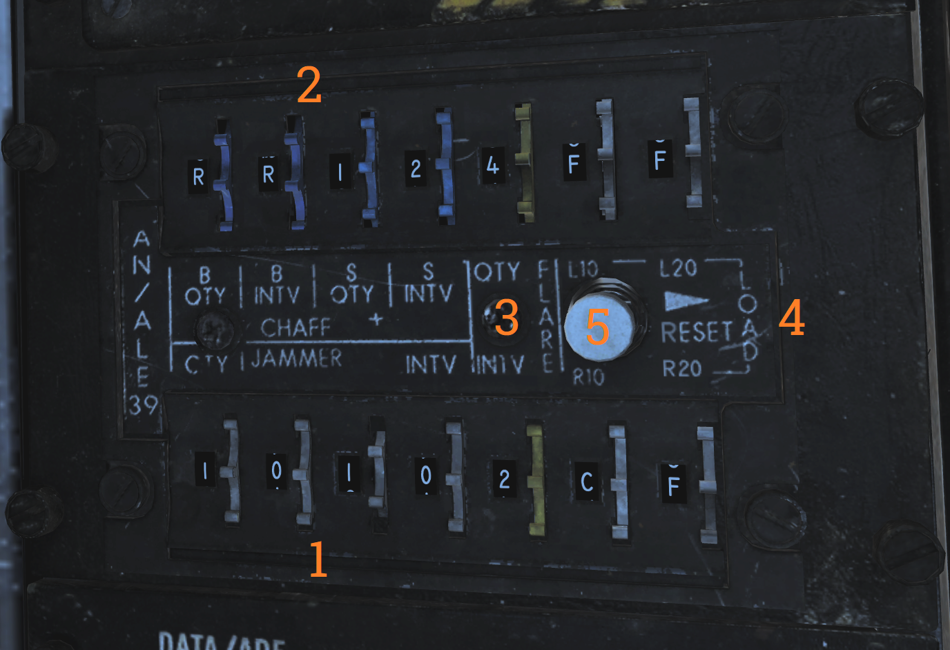 Programming panel used to program current countermeasure inventory into AN/ALE-39.
| No. | Control/Indicator | Function |
|---|---|---|
| 1 | JAMR thumbwheels | Thumbwheels used to set jammer release program. QTY - Quantity, sets quantity of jammers to release in the program. INTV - Interval, sets interval in seconds between jammer releases in the program. |
| 2 | CHAFF thumbwheels | Thumbwheels used to set chaff release program. B-QTY - Quantity, sets quantity of chaff to release in one program salvo, can also be set to C (continuous) or R (random). B-INTV - Interval, sets the interval between chaff bursts to release in one program salvo, can also be set to R (random). S-QTY - Quantity, selects the number of salvos to release in a program. S-INTV - Interval, selects the interval between salvos in a program. |
| 3 | FLARE thumbwheels | Thumbwheels used to set flare release program. QTY - Quantity, sets the quantity of flares to be released in a program. INTV - Interval, sets the interval between flare releases in a program. |
| 4 | LOAD control thumbwheels | Thumbwheels inputting into AN/ALE-39 what is loaded into each launcher subsection. L10 - Sets loaded countermeasure in Left 10 subsection. L20 - Sets loaded countermeasure in Left 20 subsection. R10 - Sets loaded countermeasure in Right 10 subsection. R20 - Sets loaded countermeasure in Right 20 subsection. |
| 5 | RESET switch | Switch loading programmed settings into AN/ALE-39 and resetting sequencer switches to their starting positions. |
Interior Light Control Panel
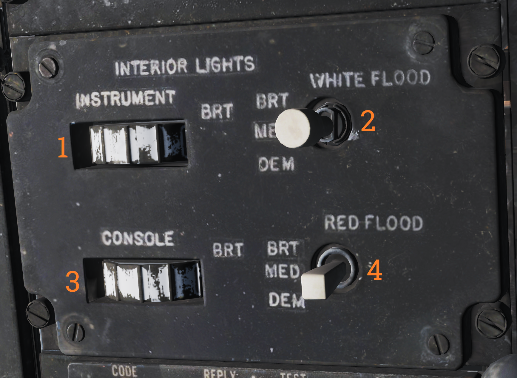 Panel controlling lights in the RIO cockpit.
| No. | Control | Function |
|---|---|---|
| 1 | INSTRUMENT thumbwheel | Thumbwheel controlling instrument panel lights, 0 equals off, 1-14 sets the lights to an increasingly bright setting. |
| 2 | WHITE FLOOD switch | Switch enabling white floodlights in the RIO cockpit. DIM and BRT (bright) settings available, switch locked to OFF unless pulled out. |
| 3 | CONSOLE thumbwheel | Thumbwheel controlling console lights and red floodlights. 0 turns off both console and red floodlights, 1-14 sets the console lights to an increasingly bright setting. |
| 4 | RED FLOOD switch | Switch controlling red instrument and console floodlights. BRT - Sets bright red instrument flood and console lights. MED - Red console floodlights. DIM - Dim red console floodlights. |
Data/ADF Switch
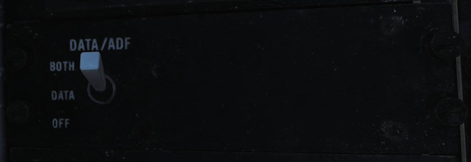 Switch controlling the display of data and ADF on the HSD and ECMD. BOTH enables the display of the ADF bug and navigation data block. DATA enables the display of only the navigation data block. OFF disables the display of either.
IFF Transponder Control Panel
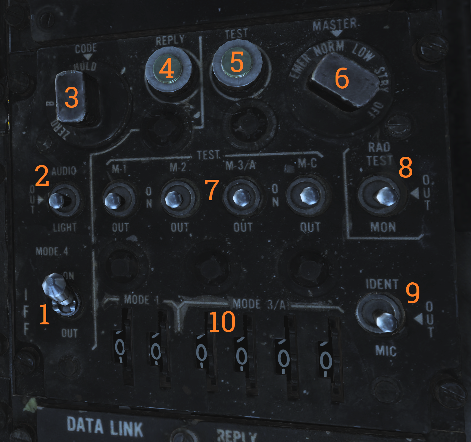 Control panel for the AN/APX-72 transponder.
| No. | Control/Indicator | Function |
|---|---|---|
| 1 | MODE 4 switch | Switch enabling mode 4. |
| 2 | MODE 4 AUDIO/LIGHT switch | Switch enabling mode 4 audio and light monitoring. AUDIO - Enables audio monitoring of mode 4 interrogation and REPLY light monitoring of mode 4 replies. OUT - Disables audio and light monitoring of mode 4. LIGHT - Enables REPLY light monitoring of mode 4 replies. |
| 3 | MODE 4 CODE selector | CODE selector switch, controlling what cipher code to use. ZERO - Erases both ciphers from the system. B - Selects the B cipher code for use. A - Selects the A cipher code for use. HOLD - Non-functional. |
| 4 | MODE 4 REPLY light | Light indicating when a mode 4 reply is generated and transmitted. Can be pushed to test the light. |
| 5 | TEST light | Light indicating correct test when the respective test switch is used. The light itself can be tested by pushing it. |
| 6 | MASTER selector | Selector switch controlling AN/APX-72 mode of operation. OFF - Disables power to the AN/APX-72. STBY - Standby, enables standby for immediate operation upon selection of other operational modes. LOW - Activates replies to set modes in low sensitivity mode, only strong nearby interrogators are replied to. NORM - Normal, replies normally to all received interrogations. EMER - Activates emergency mode replies to mode 1, 2, and 3/A, and normal reply to mode C, regardless of mode switches. |
| 7 | MODE switches | Switches controlling the operation of the different IFF modes. TEST - Tests the respective mode, correct operation if the TEST light illuminates. ON - Enables the respective IFF mode. OUT - Disables the respective IFF mode. |
| 8 | RAD TEST-OUT-MON switch | Switch allowing ground test and monitoring of non-mode 4 replies. RAD TEST - Not used by the aircrew. OUT - Disables test and monitoring. MON - Monitor mode 1, 2, 3, and C by illuminating the test light when replies are generated and transmitted. |
| 9 | IDENT-OUT-MIC switch | Switch controlling the operation of the mode 1-3 IDENT function. IDENT - Momentary position enabling IDENT reply for 15 to 30 seconds after switch release. OUT - IDENT function off. MIC - Transfers IDENT control to crewmember UHF PTT, enabling IDENT reply as per IDENT each time the PTT is keyed. |
| 10 | CODE thumbwheels | Six thumbwheels selecting the code in use for mode 1 and 3. |
IFF Antenna Control/Test Panel
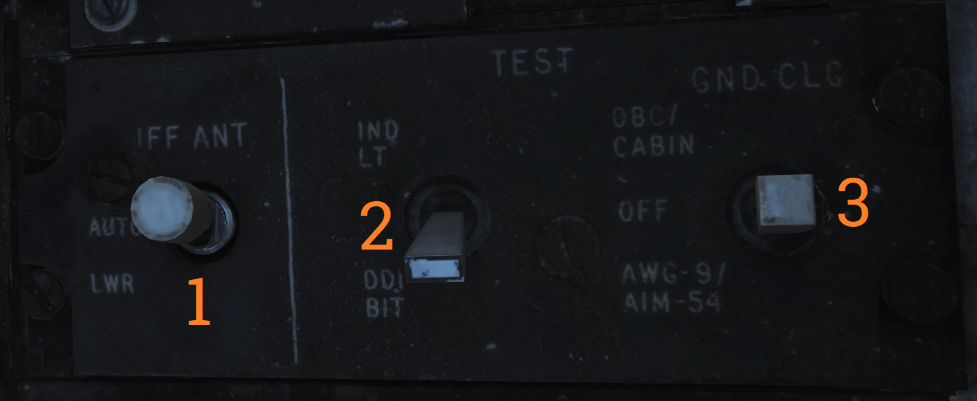 Panel containing controls for IFF antenna, tests, and ground cooling.
| No. | Control | Function |
|---|---|---|
| 1 | IFF ANT switch | Switch allowing control of which antenna the IFF transponder uses. Possible to select AUTO (automatic) or LWR (lower). |
| 2 | IND LT/DDI BIT switch | Test switch allowing manual DDI BIT and test of RIO indicator lights. |
| 3 | GND CLG switch | Switch allowing the use of external air to cool aircraft systems while on the ground. OBC/CABIN - Allows for external air into the cabin and to cool electronics and AWG-9/AIM-54 with reduced performance for OBC. OFF - External air not used for these functions. AWG-9/AIM-54 - Uses the external air to cool AWG-9 and AIM-54 coolant with better performance but disables external air to cabin. |
Mid Compression Bypass Test Panel (F-14A only)
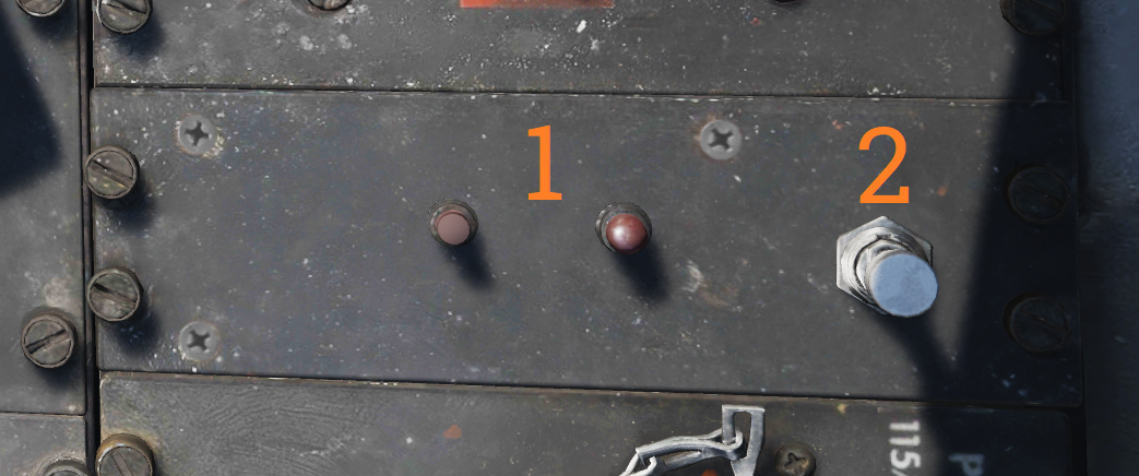 Panel containing controls and indicators used to verify Mid Compression Bypass (MCB) circuit functionality.
| No. | Control/Indicator | Function |
|---|---|---|
| 1 | Left and Right test lights | Indicators illuminating with MCB Test switch activation to indicate left and right successful MCB circuit test respectively. |
| 2 | MCB Test switch | Test switch activating MCB circuit test to verify MCB circuit functionality. |
Electrical Power System Test Panel
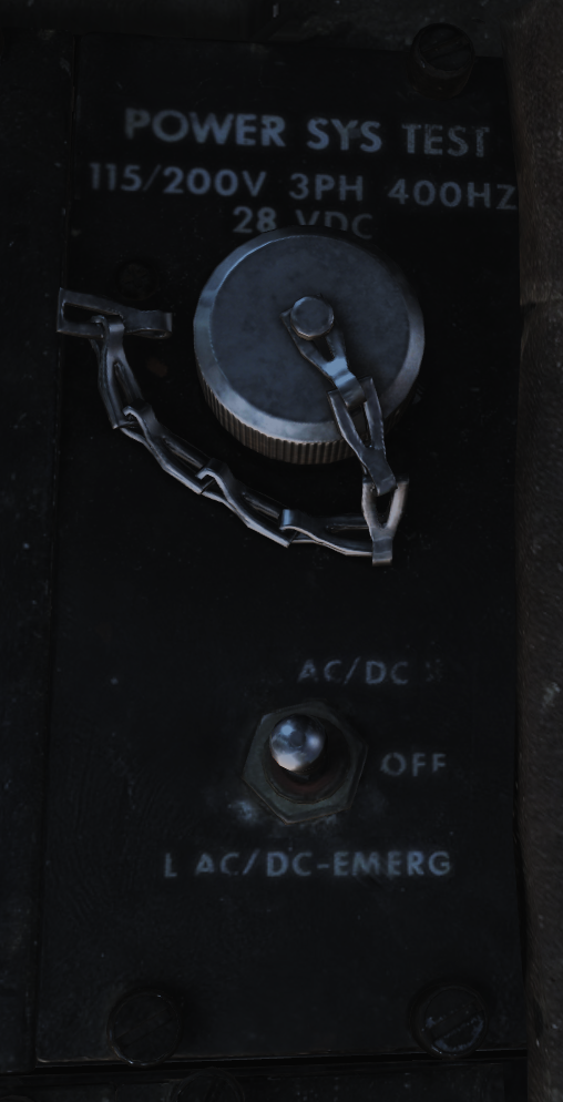 Panel used by ground crew to test aircraft electrical systems.
Note: Non-functional in DCS.
Canopy Defog/Cabin Air Lever
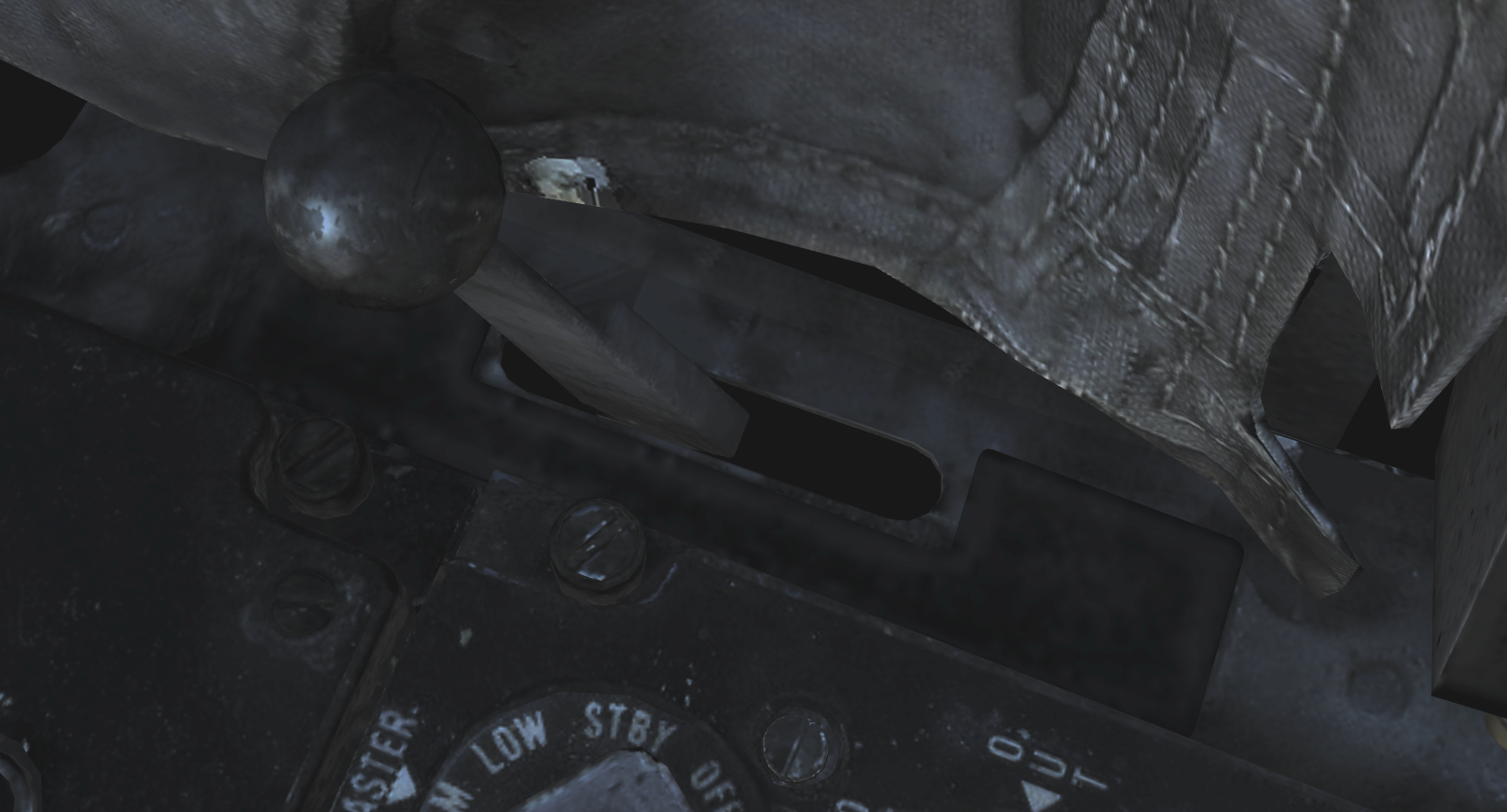 The canopy air diffuser lever controls the flow of cabin air. The normal position, CABIN AIR, directs 70% of the conditioned air through the cockpit air diffusers and 30% through the canopy air diffusers. The CANOPY DEFOG position directs all airflow through the canopy air diffusers for canopy defog.
Canopy Control Handle
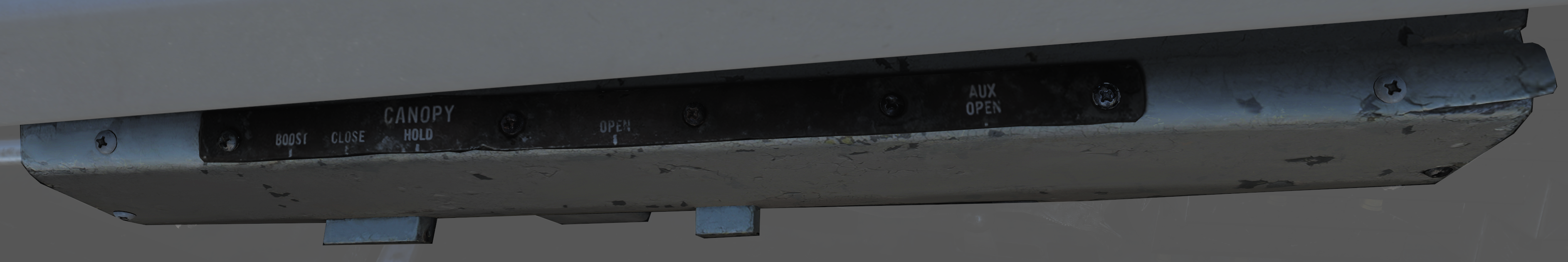 The canopy control handle controls canopy operation and is located on the right cockpit wall. The handle is mounted downwards beneath the box containing the handle mechanism and the handle position texts. The canopy control handle is duplicated in the pilot cockpit.
| No. | Control | Function |
|---|---|---|
| 1 | BOOST | Closes the canopy using boost, used during cold weather or with a strong headwind. |
| 2 | CLOSE | Closes the canopy, the default position during flight. |
| 3 | HOLD | Holds the canopy at the current position for any position other than closed. |
| 4 | OPEN | Opens the canopy. |
| 5 | AUX OPEN | Allows manual opening of the canopy if system pressure is too low. |
Canopy Control Handle
The canopy control handle controls canopy operation and is located on the right cockpit wall. The handle is mounted downwards beneath the box containing the handle mechanism and the handle position texts. The canopy control handle is duplicated in the pilot cockpit.
| No. | Control | Function |
|---|---|---|
| 1 | BOOST | Closes the canopy using boost, used during cold weather or with a strong headwind. |
| 2 | CLOSE | Closes the canopy, the default position during flight. |
| 3 | HOLD | Holds the canopy at the current position for any position other than closed. |
| 4 | OPEN | Opens the canopy. |
| 5 | AUX OPEN | Allows manual opening of the canopy if system pressure is too low. |
Systems Overview
This chapter gives detailed in-sights and explanations into all major systems of the Tomcat.
From the engine system to fuel flow, control surfaces, how to navigate, use the radar and weapons effectively, or the insights of INS alignments and its gyro system.
🚧 This section is under construction
Flight Control System
🚧 This section is under construction
This chapter contains all necessary information about the flight controls, tricycle landing gear and primary flight instruments of the F-4E.


Central Air Data Computer (CADC)
The Central Air Data Computer or CADC is the computer acting as the spider in the web for most aircraft flight sensors and relaying this information to all systems needing them. In addition, it also controls the wing-sweep via the wing-sweep schedule and also controls the flaps and slats as they are limited by that same schedule.
Flight Control System
The flight control system on the F-14 Tomcat is driven by the two main hydraulic circuits, powered by pumps connected to each engine.
For longitudinal (pitch) control both tail stabilizers are deflected in unison, acting in the same way as traditional elevators.
Lateral (roll) control is produced by both the tail stabilizers and the spoilers working in unison. To produce roll the stabilizers are deflected opposite each other to act as ailerons in combination with the spoilers on the side to which roll is commanded.
The rudders on the F-14 is a standard rudder configuration albeit in a two tail, two rudder configuration.
Control surface position is indicated on the Control Surface Position Indicator and can also be used to check trim position with controls at neutral.
Note: Above 15 units AOA, the rudders should be used for lateral (roll) control due to the different airflow along the aircraft control surfaces.
Trim
Longitudinal and lateral trim is accomplished via the trim hat on the Control Stick. This changes the stick neutral position, thus trimming the aircraft. Rudder trim is accomplished via the RUDDER TRIM switch on the Inlet Ramps/Throttle Control Panel, changing the neutral rudder position.
The Mach Trim and ITS (Integrated Trim System) automatically trims to compensate for changes in longitudinal trim. The Mach Trim system compensates for transonic and supersonic trim changes and the ITS for trim changes due to flap and speedbrake position changes.
AFCS Automatic Flight Control System
The AFCS or Automatic Flight Control System provides additional aircraft stability (SAS or Stability Augmentation System) via automatic control surface commands generated from AFCS sensors. The AFCS is controlled by switches on the AFCS Control Panel, and pitch, roll, and yaw can each be set individually.
- Pitch and roll switches: Spring-loaded to off but normally held to on by solenoids, meaning that if the system is turned off or inoperable, the switches return to off. The yaw switch is purely mechanical.
- Roll SAS: Should not be used for situations involving flight at AOA above 15 units and should therefore be set to off for combat maneuvers.
- Autopilot emergency disengage paddle: On the control stick, if held down, sets the pitch and roll channels to off.
Autopilot
Apart from stability augmentation, the AFCS is also used to provide autopilot functionality. To use the autopilot, all three stabilization channels must be enabled.
Autopilot Modes
The controls for the autopilot system are situated on the AFCS Control Panel. Available modes include:
- Attitude hold: Set the autopilot ENGAGE switch to on to maintain current aircraft attitude. Limited to within 30° pitch and 60° roll angles. The current attitude can be changed with the control stick and will be held when the stick is released.
- Heading hold: Set the HDG switch to HDG. Maneuver the aircraft to the desired heading with a bank angle of less than 5° to set the heading.
- Ground track mode: Set the HDG switch to GT, wait for the A/P REF warning light on the left side of the Vertical Display Indicator (VDI) to illuminate, and then press the nosewheel steering button on the control stick. The A/P REF warning light will turn off, and the ground track mode will be enabled.
- Altitude hold mode: Set via the ALT switch. The A/P REF warning light will illuminate until the nosewheel steering button is depressed, enabling the mode.
- Data Link Vector - Precision Course Direction mode: Allows a Link 4 controller to remotely control the aircraft. (Not modeled in DCS)
- ACL or Automatic Carrier Landing mode: Used for automatic carrier landings in conjunction with the Link 4 data link and the onboard radar beacon. Set the VEC/PCD switch to ACL, and the A/P REF warning light will illuminate. When intercepting the ACL glideslope and with the ACL READY and A/P CPLR warning lights illuminated on the VDI, depress the nosewheel steering button on the control stick to engage the ACL.
The ACL can be used in conjunction with the APC (see Throttle Controls) for a fully automatic landing. The ACL can be disengaged via the PLM button on the right throttle and the APC via the CAGE/SEAM button on the left throttle.
All autopilot modes can be overridden by enough force on the control stick or by depression of the autopilot emergency disengagement paddle, automatically resetting all autopilot switches to off.
Spoilers
The spoilers located on the upper surfaces of the wings are used to control roll as detailed above under Flight Control System, for braking on the ground as part of the Antiskid system and as a part of the DLC system (see next header).
The spoilers are only used forwards of 62° wing-sweep as further aft these conflict with the fuselage.
In case of a spoiler malfunction the spoiler symmetry protection logic disables all of the spoilers in the same section as the failed spoiler, either inboard or outboard spoilers. If this occurs the SPOILERS caution light on the Caution - Advisory Indicator illuminates.
To override this the switch corresponding to the relevant section on the Spoiler Failure Override can be set to override by lifting the guard and setting the switch to ORIDE and then depressing the MASTER RESET button on the Fuel Management Panel.
Spoiler position can be seen on the Control Surface Position Indicator.
DLC Direct Lift Control
The DLC or Direct Lift Control is used to control vertical glideslope position without pitch control inputs or engine throttle commands.
- Engagement: Engage the DLC by depressing the DLC switch on the control stick with flaps down and throttles less than MIL. This causes the inboard spoilers to extend to half and enables the DLC & maneuver flap command thumbwheel on the control stick to control them.
- Control: Rotation of the thumbwheel forwards extends the spoilers, decreasing lift and adjusting glideslope position downward. Rotation of the thumbwheel aft retracts the spoilers, increasing lift and adjusting glideslope position upward.
- Disengagement: Another depression of the DLC switch disengages the system.
Flaps and Slats
The flaps and slats on the F-14 Tomcat can be used in two modes.
- Normal flap and slat extension: Controlled using the FLAP handle on the Throttle Quadrant. The flaps can be set to anywhere between retracted and fully extended where the flaps will extend to 35° and the slats to 17°. The auxiliary flaps, the innermost section, only have two positions, retracted and extended. They will extend fully when the FLAP handle is at more than 5° extension.
- Faulty retraction: If a fault prevents retraction, move the FLAP handle to the UP position and then outboard and up to the EMER UP position to override faulty interlocks.
- Maneuver flap system: The CADC uses the flaps and slats automatically to improve aircraft performance. In this mode, the flaps extend to 10° maximum and the slats to 7° maximum, and the innermost flap section is disabled.
- Manual control: The maneuver flap system can be manually controlled using the DLC & maneuver flap command thumbwheel on the control stick. Forward thumbwheel rotation retracts the flaps and slats, and aft thumbwheel rotation extends them.
When sweeping the wings, the flaps are limited by the wing-sweep position. Aft of 21° sweep, the auxiliary (inboard flaps) are disabled up. Aft of 50°, all flaps are disabled up. The slats are not inhibited by wing-sweep.
Position of the flaps and slats are indicated on the Wheels-Flaps Position Indicator.
- FLAP light: The FLAP light on the pilot Caution - Advisory Indicator indicates a malfunction in the flap system with flaps at non-symmetrical positions.
- REDUCE SPEED warning light: The REDUCE SPEED warning light on the left side of the Vertical Display Indicator (VDI) indicates flaps not retracted above 225 knots indicated airspeed.
Speedbrakes
The speedbrakes on the F-14 Tomcat consist of three sections on the tail located between the engines and are powered by the combined hydraulic system.
- Control: The speedbrake controls are located on the right Throttle and can be set to the desired position depending on how long the switch is held to the extend position. Retraction always fully retracts the speedbrakes.
- Protection: The speedbrakes will start retracting above 400 knots and will continue to do so with increasing airspeed. Additionally, selection of MIL power or above automatically retracts them.
- Fuel dump: As the speedbrakes disturb airflow around the tail, the fuel dump is disabled with speedbrake extension to prevent the fuel from hitting the aircraft.
Position of the speedbrakes can be seen on the Wheels-Flaps Position Indicator.
Wing-Sweep System

Wing-sweep schedule as function of Mach number and related flap interlocks.
The wing-sweep system controls the geometry of the F-14’s wings, allowing the wings to move from a 20° to a 68° position in the air. While on the deck an oversweep of 75° is also possible reducing the F-14’s wing span to 33 feet (about 10 meters).
The wings are moved by hydromechanical screwjack actuators which are interconnected mechanically, making sure they’re synchronized. As long as both main hydraulic systems are functioning the maximum wing-sweep change rate is about 15°/s. This can be affected negatively by negative g or large amounts of positive g.
In normal operation the CADC, Central Air Data Computer, controls the wing position as a function of current Mach via the wing-sweep program, this is known as the AUTO mode. The pilot can also select a wing position aft of the wing-sweep program manually or choose the BOMB mode that sets the wings to 55° or further aft depending on the program. Simply put, the CADC wing-sweep program determines the max forward position of the wings. All this is done electrically via two independent channels (for redundancy) to the wing-sweep actuators.
Currently commanded wing position, CADC program wing position and actual wing position can be seen on the wing-sweep indicator next to the ACM panel.
Emergency Mode
While the normal mode controls the wing-sweep electrically, to supplement this it’s also possible to control the wing-sweep mechanically via the emergency mode. This is done via the emergency wing-sweep handle on the right side of the throttle. That handle is connected mechanically to the hydraulic valves in the wing-sweep system, providing a physical back-up control.
Normally this handle is moved with the electronic wing-sweep program by a servo located beneath it, making sure it’s at the actual wing position. To disengage the electric system and enable the emergency mode the guard over the handle is opened and then the handle is extended for additional leverage. Then the handle can be forced out of the spider-detent normally connecting it to the electrical servo and then used to manually set the wing position.
In this mode the pilot has to make sure to follow the following schedule to avoid damage to the wings:
| Speed (Indicated Mach) | Max Forward Wing Position |
|---|---|
| 0.4 | 20° |
| 0.7 | 25° |
| 0.8 | 50° |
| 0.9 | 60° |
| 1.0 | 68° |
To return to the normal mode of operation, the handle should be pushed into the desired position and pressed down and the guard closed. The MASTER RESET button on the fuel management panel should then be depressed and the wing-sweep system set to the same position as the handle. The servo will then drive to the commanded position and re-engage the handle to the spider detent, resuming normal operation.
Oversweep
The emergency wing-sweep handle is also used to select the oversweep position of the wings. The oversweep is only used while on the ground to reduce the wing span to make it easier to spot the aircraft on the carrier deck. As the wing will sweep over the stabilizers on the tail the horizontal tail authority system is enabled to prevent the wings and stabilizers from damaging each other by restricting movement of the stabilizer.
To set the wings to oversweep the emergency wing-sweep handle should be moved to the 68° position and held in the extended position. This will deflate the wing-seal airbags and activate the horizontal tail authority system, indicated by the HZ TAIL AUTH caution light illuminating. When the HZ TAIL AUTH caution light goes out and the OVER flag on the wing-sweep indicator appears the oversweep interlocks are free and the handle can now be moved to the 75° position and stowed.
To move the wings out of oversweep the handle is pulled up and moved forwards of 68°. This will again illuminate the HZ TAIL AUTH caution light. When the wings have physically exited the oversweep the caution light and the OVER flag will turn off.
As with normal emergency mode operation the handle should now be set to the same position as the spider detent and the MASTER RESET button depressed.
Controls and Indicators
The controls for the wing-sweep system are on the right throttle (electrical) and to the right of the right throttle (mechanical). See the Throttle and the Throttle Quadrant.
The wing-sweep hat on the right throttle is normally set to AUTO enabling CADC control of the wings, this is the upper position. The down position sets the wing-sweep to the BOMB mode, 55° or aft.
The AFT and FWD (forward) positions enable manual movement aft of the CADC scheduled position.
The emergency wing-sweep handle on the throttle quadrant is used to control the mechanical emergency mode, see emergency mode above.

The wing-sweep indicator to the right of the ACM panel is used to indicate the current wing-sweep positions. The pointer on the left side shows the CADC scheduled wing position. The left tape shows the manually commanded position and the right tape shows the actual wing position.
The five windows on the right side show:
- OFF: System inoperable.
- AUTO: CADC controlling wing-sweep.
- MAN: Wings set manually with the control on the right throttle.
- EMER: Wings set with the emergency wing-sweep handle.
- OVER: Wings in oversweep.
The relevant warning and advisory lights are located on the Vertical Display Indicator (VDI) and the pilot Caution - Advisory Indicator.
The WING SWEEP advisory light on the right side of the VDI illuminates when both wing-sweep electrical channels are inoperable or the emergency mode is in use. If it illuminates without the emergency mode being used that mode should then be used as the electrical system might not work.
The WING SWEEP caution light on the pilot caution - advisory indicator illuminates when at least one electrical wing-sweep channel is inoperable.
Wing-Sweep System Test
The wing-sweep system can be tested on the ground in pre-flight without moving the wings using the Master Test Panel.
To conduct the test, set the wing-sweep mode to AUTO and push the MASTER RESET button. Set the MASTER TEST switch to WG SWP.
The CADC commanded position indicator on the wing-sweep indicator will now move to 44°. The WING SWEEP and FLAP light will illuminate on the pilot Caution - Advisory Indicator and the REDUCE SPEED warning light on the Vertical Display Indicator (VDI).
Note: The WING SWEEP advisory light will illuminate after 3 seconds into test, turn off and then illuminate again at 8 seconds.
When the CADC commanded position indicator moves forward to the 20° position the test is over and the above light will turn off. The MASTER TEST switch can now be set to OFF and the test is complete. The test will take about 25 seconds to complete.
Note: The RUDDER AUTH and/or MACH TRIM lights might illuminate and the control stick might move. This can be ignored.
Note 2: The WG SWP test on the Master Test panel is not implemented yet.
Landing Gear System
The F-14 Tomcat has a tricycle landing gear designed to be fully retractable and hardened enough to withstand the rigors of carrier traps. The landing gear extension and retraction is powered by the combined hydraulic system and has an emergency extension system. The emergency extension system has a nitrogen bottle that can be used for a one-shot emergency extension. With the emergency system triggered, it needs to be reset by technicians on the ground to allow further normal retraction.
For additional information on controls and indicators, see the Landing Gear Control Panel for controls and the Wheels-Flaps Position Indicator for the indicators.
Nosewheel Steering
The nosewheel steering system on the F-14 can be activated with weight on wheels by depression of the nosewheel steering button on the Control Stick. The activation of this system is indicated via the NWS ENGA caution light on the left side of the HUD, see Wheels Warning/Brakes Warnings/ACLS/AP Caution/NWS Engage Caution/Auto Throttle Caution Lights.
Disengagement of this system occurs automatically with weight off wheels (take-off), electrical supply failure, or lowering of the launch bar. It’s also possible to deactivate the system by depression of the nosewheel steering button.
The nosewheel, with the system engaged, is controlled via the rudder pedals. It’s capable of a deflection of up to 70°, meaning that it will turn tightly enough that the inner wheel will move backward.
Wheelbrakes
The wheelbrakes can be applied either via the rudder pedals by pressing on the upper part of them, rotating them forwards. The other application is via the parking brake handle located on the Landing Gear Control Panel panel.
The rudder pedals can be used to apply the brakes gradually while the parking brakes are either on or off.
Normally both systems are supplied from the combined hydraulic system but if that system becomes depressurised the brake system automatically switches to the backup accumulators. The Emergency Brake Pressure Indicator shows current pressure in the emergency accumulators.
If fully charged the auxiliary accumulator allows for about 13 to 14 wheelbrake applications from the pedals and the parking brake accumulator 3 parking brake applications minimum. These accumulators can be recharged via the Hydraulic Hand Pump.
The BRAKES warning light on the left side of the HUD indicates either parking brake applied, antiskid system fail or that the brakes are operating in the emergency mode (only when the pedals are depressed).
Antiskid
The antiskid system modulates the wheelbrakes to prevent skidding while on the ground. When armed in the air the system prevents braking until both main wheels are on the ground and the wheels have spun up. Also the system is not operational below 15 knots.
The antiskid system switch also controls the spoiler brake system that deploys the spoilers as brakes when the throttles are set to IDLE while on the ground.
Note: The antiskid should be disabled during taxi as below 15 knots, the system may disturb normal braking even though the antiskid feature is not operational at those speeds.
The ANTI SKID SPOILER BK switch on the Fuel Management Panel panel controls the system. OFF disables the system, BOTH enables antiskid and the spoiler brake system and SPOILER BK enables only the spoiler brake system.
Catapult Launch and Arresting Gear
Nosegear Catapult System
The nosegear of the F-14 contains the system allowing for catapult assisted takeoff during carrier based operations.
The three components mounted in or on the nosegear are the nosewheel kneel functionality, the launch bar and the holdback fitting.
To enable the system the aircraft is kneeled using the NOSE STRUT switch on the Landing Gear Control Panel. This is done by holding the switch to the KNEEL position until downward movement stops.
This drains hydraulic fluid from the shock absorber, compressing the nosegear strut 14 inches. When compressed this also releases the lock on the launch bar which can then be lowered manually by the deck crew or by turning the nosegear more than 10° from center.
Note: In DCS, the launch bar is automatically lowered with nosegear kneel.
The aircraft can then be guided onto the catapult and connected to the shuttle, in DCS via default keybind U. The holdback bar is currently not modelled in DCS.
Note: Deselection of nosewheel steering should be done before final movement onto the shuttle and hookup to avoid misalignment.
The final command to launch the aircraft, after proper procedures, is then to salute the “shooter” or officer in command of catapult launch, default keybind Left Shift + U in DCS.
After the catapult stroke, when the launch bar is released from the shuttle, stored hydraulic energy is released to impart a positive pitch moment to the aircraft. This also automatically raises the launch bar into its stowed position.
Indication of the launch bar status is available on the Caution - Advisory Indicator via the LAUNCH BAR advisory light. The advisory light is on with weight on wheels when the launch bar is not up and locked and turns off if throttles are advanced to MIL to enable a lights out for launch criteria. With weight off wheels the LAUNCH BAR advisory light is on if the nose strut hasn’t fully extended, launch bar is not up and locked or nosewheel hasn’t centered correctly. This inhibits nosegear retraction.
The Launch Bar Abort Panel contains the LAUNCH BAR switch used to disengage the launch bar in case of an aborted launch. This functionality is currently not implemented in DCS, unhooking the launch bar is currently accomplished by another depression of the hookup key, default key U.
Arresting Gear
The arresting hook located on the underside of the tail of the F-14 is used for arrested landings during carrier operations.
The system uses hydraulic power from both flight and combined hydraulic systems and is controlled electrically, thus requiring electrical power as well.
Operation of the system is via the arresting HOOK handle on the Arresting Hook Panel. UP raises the arresting hook and DN, down, lowers it to 37° allowing it to catch the wire during a correctly executed carrier “trap”. The transition light next to the arresting HOOK handle illuminates whenever the arresting hook position does not correspond with handle position.
If on board failures do not allow for normal hook lowering it’s possible to use a mechanical backup to deploy the hook. To activate the mechanical backup, pull the handle out and rotate it 90° counterclockwise. This releases the mechanical uplock and drain the hydraulic pressure keeping the hook up, thus lowering it.
If electrical power and hydraulic power are restored, it’s then possible to retract the hook by rotating the handle 90° clockwise and pushing the handle back in and then setting it in the default UP position.
Note: Hook position also affects the AoA indexer and approach lights, making them flash with gear down if the hook is not also down. This feature can be disabled using the HOOK BYPASS switch on the Master Light Control Panel.
Engines and Fuel System
"This baby will go, and old Smokey will never catch it, because it's got a state-of-the-art fuzz buster inside. Now, it's not legal in all countries, but I'll tell you what, Cal won't tell, no siree."
The F-4E Phantom II is equipped with two General Electric J79-GE-17A/F engines. A turbine-type starter, powered by external air or the expanding gases of a solid propellant cartridge, is employed for engine cranking during starting.

It also features an internal fuel system comprising interconnected cells in the fuselage and two internal wing tanks. External fuel can be carried in two wing-mounted 370-gallon tanks and a 600-gallon fuselage-mounted tank.
Engines and Throttle Controls
The F-14A is powered by two Pratt & Whitney TF30-P-414A while the F-14B is powered by two General Electrics F110-GE-400, both of which are afterburning turbofan engines.
To provide the engines with an even subsonic airflow the F-14 has the AICS or Air Inlet Control System. This system controls the variable geometry intakes by moving the variable ramps mounted in them to slow the airflow. This is accomplished using various sensor inputs run through a calculation using set schedules which decides the positions of the ramps.
In addition, the TF30 uses two systems to improve reliable operation, the Mid Compression Bypass System (MCB) and the Mach Lever.
The MCB helps mitigate high angle of attack airflow onto the compressor fans to reduce the risk of an engine stall. This system vents air from the compressor section to bypass duct to stabilize the airflow for later compressor stages. Normally this system uses angle of attack and Mach number sensor data to activate, but with the landing gear handle in the down position this it is only activated with zone 5 afterburner. Additionally the WCS commands the MCB to activate with extension of the refuelling probe as well as when launching AIM-7 or AIM-9 missiles, air to ground rockets or firing the M61 Vulcan gun.
The Mach Lever also mitigates the risk of an engine stall by controlling min and max rpm allowed as a function of Mach number. In addition it also increases the minimum rpm in high angle of attack regimes while subsonic.
The two F110s in F-14B, on the other hand, are controlled by the AFTC (Augmenter Fan Temperature Control unit). The AFTC is an early engine control computer akin to an early version of a FADEC (Full Authority Digital Engine Control) used on newer turbine engines. This system controls both the engine itself as well as the variable exhaust nozzles controlling the engine exhaust gases and removes the need for the MCB and Mach Lever for the F110. The lack of such a system in the F-14A controlling its TF30s is one of the reasons for them being deemed less reliable than the F110s.
In case of a failure in the AFTC the MEC (Main engine control) is capable of assuming control of the engines to provide a fall-back, mechanical control. The normal mode, AFTC, is the primary mode (PRI) and called as such while the fall-back MEC is the secondary (SEC) mode. The selection of primary or secondary is automatic in case of a failure in the AFTC but can also be manually selected. Of note is that in secondary mode the engine nozzles are fully closed and disabled in addition to the afterburners being disabled with a corresponding loss of engine performance.
In addition both engines also drive separate fuel, hydraulic and electric generators to create redundancy.
Note: The main difference between the TF30 and F110 engines (apart from lesser thrust in the TF30s) is that the TF30s are more sensitive to the quality of the airflow entering the compressor face. In general it is wise to avoid anything less than military power or afterburner while in high angle of attack maneuvers as well as avoiding large rudder inputs or asymmetric engine throttle settings. That said, the TF30s in the HB F-14A module have been extensively tuned using available data and SME expertise, resulting in an accurate modelling of an engine undeserving of its bad reputation. One “advantage” of the TF30’s mechanical fuel control is its high speed thrust, resulting in higher top speeds than the F110 can achieve. If flown within normal parameters, the TF30 engines behave well if a tad underpowered compared to the F110s.
Throttle Controls

The throttles in the F-14 have detents preventing unintentional engine start and shutdown and unintentional selection of afterburner. In addition the throttles also controls several different systems depending on throttle position as shown in the diagram above. The most critical of these being the fuel cutoff and ignition systems in the respective engines.
For throttle operations there are three modes:
- Manual Mode: A mechanical mode in which the engines are controlled by mechanical linkages directly from the throttles to the engines. The manual mode is designed as a backup mode and may be inexact because of the mechanical nature of the controls.
- Boost Mode: The normal mode of operation in which electrical paths control actuators moving the same engine controls as the mechanical linkages but more exactly and with lesser force required.
- Approach Power Compensator Mode (Auto Throttle Mode): A system which allows for automatic throttle control for optimal angle-of-attack during approaches.
The controls for the throttle mode are located on the inlet ramps/throttle control panel to the side of the main throttles and allows for selection of all three modes. The auto throttle mode is solenoid held and will revert to boost mode if the criteria for automatic controls are not met.
To allow selection of auto mode the throttles need to be between 75 to 90% rpm, the gear handle needs to be down and with no weight on the wheels. If these criteria are no longer met, the throttles are manually overridden with force or the Cage/SEAM button on the left throttle is depressed the solenoid releases the switch and it reverts to boost.
For additional autothrottle tune the gain of the system can be set on the inlet ramps/throttle control panel. The settings are hot, normal or cold with hot increasing the throttle gain (and effective thrust) and cold decreasing it. These settings correspond to cold or hot external temperatures but should be set according to observed throttle control.
The RATS or reduced arrestment thrust system is a system limiting engine thrust after touchdown to limit it to levels appropriate for carrier environments. The system is enabled by weight on either main landing gear and is disabled by selection of afterburner on the throttles.
Finally, and implemented only for the F110-GE-400, is the asymmetric limiter, preventing asymmetric afterburner engagement if only one afterburner lights by keeping that afterburner at minimum afterburner thrust until the other afterburner also lights.
Engine and Throttle Control Switches and Indicators

The inlet ramps/throttle control panel contains most other engine related controls.
- THROTTLE MODE switch: Sets throttle mode to AUTO, BOOST or MAN modes respectively, with auto being spring-loaded back to boost but held in place electrically as mentioned above.
- THROTTLE TEMP switch: Controls the gain of the automatic throttle system also described above.
- INLET RAMPS switches: Enable (AUTO) or disable, stow (STOW) the variable intake ramps.
- Engine crank switch: Used to crank the engines to 20% rpm allowing for engine start by moving the respective throttle to idle from cut-off. The air to start the engine is sourced from an external air supply if connected or the other engine if no external source exists. At 50% rpm the crank switch automatically returns to off/center position. If this does not occur it should be manually set to off to prevent damage to the air turbine starter.
- BACK UP IGNITION switch: Enables the backup ignition system in case of a failure in the main ignition circuits that are normally enabled by moving the throttles out of the cut-off position.

Note: F-14B only.
- ASYM LIMITER switch: On the ASYM limiter/engine mode select panel enables or disables the asymmetric afterburner thrust limiter. Default position is ON and the switch has a guard cover keeping it in that position.
- ENG (engine) MODE SELECT switches: Setting the left (L ENG) and right (R ENG) to PRI, primary or SEC, secondary modes respectively.

Note: F-14A only.
The MCB Test Panel, located in the RIO pit on the right horizontal panel, is used to test if the MCB system functions. The TEST switch set to the TEST position activates the test circuit which lights the two test lights for the left and right engine respectively if their MCB circuits function.

The ENG/PROBE ANTI-ICE switch on the external environmental control panel enables the engine anti-ice and intake ramp anti-ice mode in addition to the various probe heaters. The ORIDE position enables the system, the AUTO position enables the system if icing is detected and the OFF position disable it.
Engine Instrument Group (EIG), Related Indicators and Caution Lights

The ENGINE INSTRUMENT GROUP displays engine RPM, TIT (Turbine Inlet Temperature, F-14A) or EGT (Exhaust Gas Temperature, F14B) and FF (fuel flow) to the pilot to allow for engine monitoring.
Note: Pictured above are the TF30 engine indicators, F110 EIG coming soon.

The exhaust nozzle position indicators display respective engine’s current engine exhaust nozzle position, with zero being fully closed and full clockwise rotation being fully open. The F-14A indicates 0 to 6 units while the F-14B indicates 0 to 100 percent open (tens indicated on gauge).

The oil pressure indicators display respective engine oil pressure allowing the pilot to check that engine oil pressure is at acceptable levels.
The caution lights relevant to engine operation are located on the pilot’s caution - advisory panel, and at the sides of the HUD.
The caution lights on the sides of the HUD are the engine stall warning lights which flashes at a 3 Hz rate when an engine stall is detected. The warning light on the left side of the HUD indicates an engine stall in the left engine and the one on the opposite side the right engine. This is also combined with an audio warning, a modulated tone at 320 Hz.
Below the left engine stall warning light is, amongst others, the AUTO THROT (auto throttle) caution light which illuminates for 10 seconds when the auto throttle system is disengaged by other means than the throttle mode switch.
On the main caution - advisory panel the relevant engine caution and warnings lights are:
- INLET ICE: Caution light indicating ice detection on the detector in the left engine inlet.
- L & R INLET: Caution lights indicating failure in AICS for respective variable intake system.
- OIL PRESS: Caution light indicating low oil pressure in either engine.
- BLEED DUCT: Caution light indicating hot air leakage in either engine.
- L & R RAMPS: Caution lights indicating respective engine intake ramp not being locked into position when supposed to.
- L & R GEN: Caution lights indicating that respective engine generator is inoperative.
- L & R OIL HOT: Caution lights indicating that respective engine oil is too hot.
- L & R FUEL PRES: Caution lights indicating engine fuel pressure below 9 psi in respective engine fuel boost pump.
F-14A TF30-P-414A only lights:
- L & R OVSP/VALVE: Caution lights indicating engine starter system malfunction or N1 rotor overspeed in respective engine.
F-14B F110-GE-400 only lights:
- START VALVE: Caution light indicating that the starter valve is open. Control engine crank position if lit after engine start completion.
- L & R ENG SEC: Caution lights indicating that respective engine is operating in secondary mode.
- RATS: Caution light indicating that RATS (reduced arrestment thrust system) is enabled.
Note: F-14A specific lights not yet implemented.
Fuel System

- Refueling Probe, 2. Ground refueling Port (Right Side), 3. Forward Fuselage Tank, 4. Left External Drop Tank, 5. Left Box Beam Tank, 6. Left Wing Tank, 7. Vent Tank, 8. Fuel Dump Mast, 9. Aft Fuselage Tank, 10. Right Box Beam Tank, 11. Right Wing Tank, 12. Right External Drop Tank.
The main fuel storage in the F-14 consists of two feed systems, one for each engine. The right engine feed system consists of the right wing and right box cells and the front fuselage cells while the left engine feed system consists of the left wing and left box cells in addition to the aft fuselage cells. This fact needs to be kept in mind when reading the fuel gauges.
The total usable fuel quantity is roughly 20,000 pounds distributed as in the table below.
| Tank group | Pounds |
|---|---|
| Forward Fuselage | 4,700 |
| Aft Fuselage | 4,400 |
| Right Feed Group | 1,600 |
| Left Feed Group | 1,500 |
| Internal Wings | 4,000 |
| External Tanks | 3,600 |
Fuel Quantity Indicators and Controls

The fuel quantity indicator on the pilot right knee panel displays internal and external fuel carried.
- BINGO indicator: Displays currently set BINGO fuel level, this quantity is set by rotating the knob (5) to desired amount. This indicator and control activates the BINGO caution light when total fuel level is below set amount.
- TOTAL indicator: Displays total carried fuel.
- L and R indicators: Normally shows fuel carried in left and right fuel feeds respectively. A rocker switch on the fuel management panel enables selection of the wing internal tanks (WING) or external fuel tanks (EXT) for display but is spring-loaded to return to showing the feed tanks (FEED) automatically. When displaying wing internal tanks or external fuel tanks, the left wing or left external tank is shown on the L counter and the right wing or right external tank on the R counter.
- FUS & FEED tapes: Shows the AFT & L (aft fuselage and left feed) and FWD & R (forward fuselage and right feed) in thousands of pounds.
- SET knob: Used to set BINGO fuel quantity. Turn to set desired quantity.
Additionally the RIO has a total fuel quantity display on the right instrument panel. This display counter can only show total fuel quantity. (See Fuel Quantity Totalizer.)

The fuel management panel on the pilot’s left vertical console contains the applicable controls for the fuel system.
- QTY SEL rocker switch: Detailed above under the description above about the L & R fuel displays.
- FEED switch: Allows the pilot to correct fuel imbalances caused by single engine operation or feed failures by selecting both engines to feed from either the FWD (forward and right tanks) or AFT (aft and left tanks) instead of from one feed system each as normal NORM. The switch guard locks the switch to the NORM position when down.
- WING/EXT TRANS switch: Controls fuel transfer from the wing and external tanks into the fuselage feed systems. The normal AUTO position enables this transfer as soon the landing gear is retracted. The ORIDE position enables this transfer regardless of landing gear position, enabling transfer when on the ground or during a malfunction in the electrical system inhibiting landing gear retraction detection. Additionally the OFF position disables this transfer but can be overridden automatically to AUTO when the INST test is performed on the MTS panel, the refuel probe is set to ALL EXTD or when dumping fuel.
- DUMP switch: Enables fuel dump through the beaver tail fuel dump mast, it also enables all fuel transfer systems, enabling dump of fuel in wings and external tanks in addition to the fuselage. If there’s weight on the wheels or the speed brake is not fully retracted the fuel dump is inhibited.
Note: Even though technically possible to engage the afterburners after a fuel dump is in progress, this is not allowed due to the possibility of igniting the dumped fuel.
In-Flight Refueling
The above panel also contains the control for the in-flight refueling system.
- REFUEL PROBE switch: Controls the extension of the refueling probe as well as setting up the fuel system to receive fuel. The two extended positions (EXTD) are ALL, enabling refueling of all tanks, including wings and external tanks and FUS, allowing refuel of only the fuselage tanks. When selecting the ALL position the fuel feed from the wings and external tanks are disabled to allow refueling of these tanks. RET (Retract) retracts the refueling probe and resumes normal fuel system operation.
Note: Selecting EXTD ALL resets the WING/EXT TRANS switch to AUTO.
Navigation & Communication
The F-14’s primary navigation system is a multi-unit Carrier Aircraft Inertial Navigation System (CAINS) designated as AN/ASN-92. An INS system measures and integrates sensed inertia forces (acceleration) and rotational velocities to calculate aircraft position and linear velocity. A good navigation system can precisely guide an aircraft on a route to a mission objective hundreds or thousands of miles long, and then back to the home base, safely and reliably. Such a system is even more important when an aircraft is designed to operate over the ocean, far away from any ground-based TACAN or visual references.
Designing an INS (IMU) is an engineering challenge, which requires consideration of such problems as calibration, alignment, Earth’s rotational motion, inertia forces, thermal stability, analogue-digital converters precision, all different types of corrections which have to be applied to keep the device precise over extended time, and many more. Simulating an INS platform is very similar - it is a complex undertaking.
At Heatblur, we decided to develop an entirely new mathematical model to simulate the AN/ASN-92 for our F-14. We included all the potential sources of errors contributing to the final precision of the device, and recreated the characteristic behavior of a gimballed INS platform. The result is a set of algorithms providing an authentic representation of the AN/ASN-92 in DCS, yet optimized to have almost no impact on CPU performance.
The main components of the INS are the inertial measurement unit (IMU), the power supply unit, and pilot and RIO navigation controls and displays.
Although from the crew member’s point of view, the INS is used mostly for navigation, it is also essential for proper operations of other aircraft equipment. For example, the attitude is necessary for the radar. The attitude and the own position are required for some weapon delivery modes, particularly for long shots. Even more distressing to the crew, a complete failure of the INS renders the more advanced modes of weapons such as the AIM-7 and AIM-54 missiles inoperable.
The same information is used for data-link operations - when using erroneous INS data, own tracks and targets received from cooperating aircraft will not match and result in false contacts being displayed on the TID. These are only a few examples, and the INS data is used whenever aircraft position or attitude is required.
Thus, the inertial navigation system (INS) integrates with the AWG-9 computer (WCS computer) and the CSDC, the computer signal data converter. Other related equipment includes the attitude and heading reference system, central air data computer, radar altimeter, instrument landing system, and TACAN.
Navigation System
WCS Computer
The WCS or weapon control system computer and CSDC use several alignment routines stored on a magnetic tape to perform the necessary computations to align the INS.
These stored alignment routines in the WCS computer are called SMAL single mode alignment program. When alignment is initiated, the routines are loaded in the computer’s destructive readout memory from magnetic tape.
This process is called “tape read-in” and is represented by an M on the TID. During the alignment of the IMU platform, the WCS communicates with the CSDC to address specific CSDC navigation routines.
IMU Platform Alignment
When alignment mode is selected, the IMU platform first erects to a coarse alignment with the help of accelerometer output and gives an aircraft heading that represents the angular displacement from true north. This displacement is referred to as wander angle. The CSDC sends inertial velocity data to the WCS during the alignment process.
The second stage – fine alignment – uses the precise measurement of gyroscope drift to calculate the aircraft’s true heading. This is possible because of the Earth’s rotation. At no point of alignment, is the magnetic heading used, and the whole process relies only on the sensing of the non-inertial movement of the platform within the 3D space.
The WCS calculates terms for platform alignment corrections and estimates the value of the wander angle, then sends this data to the CSDC. The CSDC uses these correction terms in the CSDC inertial equations to generate pulses for the platform torquing that are then transmitted to the IMU. The CSDC in return receives velocity information from the IMU and sends this new inertial velocity data to the WCS alignment program, upon which the cycle repeats. The exchange of data continues until INS is entered.
The leveling process of the platform is achieved by the CSDC generating torquing pulses based on IMU accelerometer off-level indications being sent to the IMU by the CSDC. With each data exchange, the WCS calculates an error value (delta) between the values of the previous and current wander angle. This delta is largest at the beginning of the alignment and smallest at the end of alignment.
The alignment is finished when the delta is near zero and near zero velocity is sensed along the platform X and Y axes. Variable factors required to align the platform are continuously calculated, updated, and saved as calibration data. When the alignment is complete, the system is ready to enter INS. The last used calibration data and wander angle are stored in the CSDC upon entry into INS. When in INS, the WCS accepts the velocity and position data and the wander angle from the CSDC.
Navigation Modes
Three navigation data mode sources are used for general navigation:
-
INS - The primary navigation mode set by the RIO once IMU alignment is complete. The IMU is the primary sensor supplying velocity data that is used to compute all inertial outputs. The IMU is the source for roll and pitch data.
-
IMU/AM - A backup mode that can either be selected by the RIO or is automatically entered when the CSDC determines the IMU inertial velocity data is unreliable. In this mode, true airspeed from the CADC and stored or entered winds are combined to provide ground speed and true heading for general navigation. The IMU is the source for pitch and roll.
-
AHRS/AM - An even further degraded mode that can be either selected by the RIO or automatically entered when the CSDC detects a total INS failure. Heading in this mode is derived from magnetic heading plus entered or stored magnetic variation (MAG VAR). This heading, TAS from the CADC, and entered or stored wind are used for general navigation. The AHRS is the source of pitch and roll.
Navigation Computations
The CSDC and the WCS are aware of the selected navigation mode. The CSDC sends the WCS navigation data parameters (TAS from the CADC, latitude and longitude, inertial velocities, true heading, etc.) required to support general navigation calculations. The WCS uses stored and input navigation data (based on the current navigation mode) to perform the required navigational computations. The WCS also performs additional computations so that the crew is provided with:
- Current latitude and longitude
- Attitude
- Heading true and magnetic
- Own ground speed and ground track
- Ability to store and display three waypoints, a fixed point (FP), an initial point (IP), a surface target (ST), a home base (HB), a defended point, and a hostile area
- Range, bearing, command course, command heading, and time-to-go to a selected destination point
- Calculated wind speed and direction
- Calculated magnetic variation
- Continuous monitoring of the status of the unit, and in case of failure inform the crew with advisory lights and appropriate acronyms displayed on the TID
- Backup navigation modes in case of partial system failure
- Backup present position
Displays
Navigation information is displayed on the TID, HSD, multiple display indicator (MDI), HUD, and VDI, depending on the mode selected by the pilot and RIO. If an IMU or navigation computer failure occurs, two backup modes are available: IMU airmass (IMU/AM) or AHRS airmass (AHRS/AM).
Navigational Controls
To control the INS, use the navigation control and data readout panel and the computer address panel. See Tactical Information Display (TID) and Associated Controls and Associated Controls and Computer Address Panel (CAP) for a more detailed description.
The desired operation mode, alignment mode, and destination point can be selected at the navigation control and data readout panel. The CAP allows entering navigation data and the selected information to be displayed on the TID. The CATEGORY switch on the lower end of the panel determines the function of the MESSAGE button. The categories used for navigation are NAV and TAC DATA. The STBY and READY advisory lights on the navigation control and data readout panel indicate the status of the alignment program and navigation system.
Failure indicators for the main components of the navigation system are on the caution/advisory light panels in both cockpits, however, the NAV COMP and IMU indicators are only present on the RIO cockpit caution/advisory light panel.
The pilot displays (HUD, VDI, and HSD) and the RIO multiple display indicator are controlled with either the pilot display control panel or the multiple display indicator control panel.
Note: For detailed information on CAP operation, refer to Computer Address Panel (CAP).
Navigation Category
If the CATEGORY switch is in NAV, the following matrix appears in the MESSAGE windows:
OWN
A/C
TACAN
FIX
STORED
HDG
ALIGN
RDR
FIX
VIS
FIX
WIND
SPD HDG
FIX
ENABLE
MAG
VAR
(HDG)
Each window has a designated button. Pressing this button tells the WCS computer which function of the matrix to use. If OWN AC, WIND, or MAG VAR is pressed, data can be entered and displayed for each.
Own-aircraft airspeed and magnetic heading are displayed on the TID. If own-aircraft data file is hooked using the TID cursor, heading will be magnetic. If OWN AC button was selected (hooked) via the CAP, own-aircraft true heading, speed (groundspeed), altitude, or course can be displayed on the TID by depressing the appropriate prefix button:
- LAT or LONG button will display own-aircraft latitude and longitude.
- SPD button displays ground speed and magnetic course.
- True airspeed and true heading are displayed when the HDG prefix button is depressed.
- Altitude is displayed on the left TID readout (right is blank) when the ALT button is used.
- When pressing the WIND button, the TID displays present wind speed (left readout) and magnetic direction (right readout).
- The MAG VAR button is used for displaying and entering magnetic variation (MAG VAR).
In order to change own-aircraft lat, long, true heading, or altitude, press the according prefix button followed by the desired quantity. During entry, the data is displayed on the upper middle readout on the TID. At the same time, existing data is being displayed on the two lower readouts. If new data is correct, the RIO can press the ENTER button and the new values will appear on the readout.
To change wind data entry, press the WIND button, then either the SPD or HDG prefix button and the appropriate numbers: knots (0 to 512) for speed or degrees (000 to 359) for magnetic direction. The multiple display indicator data readout of WIND direction is always displayed as true.
Note: In the INS mode, wind is calculated and updated continuously. The manual entry of wind is ignored by the wind calculations even though the system accepts the entry.
Depressing the MAG VAR button displays alternating values of computed MAG VAR (vC) and manual MAG VAR (vM) on the left readout and displays magnetic heading (MH) on the right readout. The two values alternate every 2 seconds. On the CAP sign/direction buttons, plus (+) corresponds to east variation and minus (-) to west variation.
For manual MAG VAR, press the MAG VAR button. Press HDG, E, or W, the angle in degrees and tenths, and ENTER. Tenths of a degree must be entered even if zero. The TID displays including the NAV GRID will shift appropriately. Computed MAG VAR is constantly calculated in the AWG-9 by comparing the IMU’s true heading with the magnetic heading from AHRS. This difference is saved as computed MAG VAR. The table below shows the MAG VAR source used by the computer for displays and CAP entries.
Computed MAG VAR and manual MAG VAR are compared by the AWG-9 computer. If they differ by a certain value, the acronym MV will alternate with the IN or IM navigation mode acronym on the TID and HSD. The acronym is cleared when the difference falls below 5°.
| Condition | MAG VAR source |
|---|---|
| COMP mode selected. | Manual MAG VAR (vM). |
| RIO updating manual MAG VAR after AHRS selection. | Manual MAG VAR (vM). |
| RIO updating manual MAG VAR after IMU or AHRS failure. | Manual MAG VAR (vM). |
| All other situations. | Current or last computed MAG VAR (vC). |
If the selection of AHRS/AM occurs and no update (or re-entering of the same value) occurs last vC will be used.
Note: When operating in SLAVED or COMP mode near a magnetic disturbance, such as aboard a carrier, the MV acronym should be expected to appear.
The table below shows error source analysis and response to the MV acronym appearing in flight.
| Step | Condition | Action | Result |
|---|---|---|---|
| 1 | MV alternates with selected nav mode on TID without a failure light present. | Re-enter new corrected MAG VAR. | MV acronym should disappear. |
| 2 | MV remains after step 1 action. | Compare heading on VDIG with standby compass while in INS, IMU/AM, or slaved compass mode and level unaccelerated flight. | If headings correlate, the problem is likely in the IMU. Continue with step 3. |
| 3 | Source of suspected vC error is the IMU. | Pilot switches to COMP mode on AHRS controller and again compares headings. | If the headings still correlate, the IMU heading is wrong. |
| 4 | IMU heading is wrong. | RIO selects AHRS/AM and enters correct MAG VAR. | MV acronym should disappear. |
| 5 | The VDIG does not agree with the standby compass in step 2. | Synchronize AHRS with depression of the HDG button. If not possible set AHRS to COMP mode. | If now in COMP mode all computer and displays will use IMU true heading with manual MAG VAR. The MV acronym might not disappear and the BDHI using the MAD might not be correct depending on the failure. |
Tactical Data Category
If the CATEGORY switch is in TAC DATA, the following matrix appears in the MESSAGE windows:
WAY
PT
1
HOME
BASE
WAY
PT
2
DEF
PT
WAY
PT
3
HOST
AREA
FIX
PT
SURF
TGT
IP
PT
TO
PT
The functions in this category have a TID symbol each, except the PT to PT FUNCTION. When pressing any one of these MESSAGE buttons, the TID symbol brightens and the activated MESSAGE push button illuminates, indicating a successful hook. The RIO can then use the functions for which hooking was required. Data regarding the hooked point can be displayed on the TID by pressing the according prefix button. Additionally, the latitude, longitude, and altitude of the hooked point can be entered by pressing either the LAT, LONG, or ALT button followed by the desired numbers. Like before, existing data is being displayed on the two lower readouts. If the new data is correct, the RIO can press the ENTER button and the new values will appear on the readout.
Navigational Caution Lights
In addition to the NAV COMP, AHRS, and IMU lights mentioned above, the RIO caution/advisory panel contains two other advisory lights, C&D HOT and AWG-9 COND, that are indirectly related to navigation system operation. Illumination of either or both of these lights could mean degraded navigation operation and would require further investigation of the WCS.
Radar Altimeter System (AN/APN-194)
The radar altimeter is a low-altitude (0 to 5,000 feet), pulsed, range-tracking radar that measures the surface or terrain clearance below the aircraft. Altitude information is obtained by radiating a short-duration RF pulse from the transmit antenna to the Earth’s surface and measuring elapsed time until RF energy returns through the receiver antenna. The altitude is continuously presented to the pilot on an indicator dial in feet AGL. If either Landing or Take off mode is selected on the PDCP, radar altitude is displayed on the HUD from 0 to 1,400 feet.
The radar altimeter can operate in two modes. In the search mode, the system successively examines increments of range until the complete altitude range is searched for a return signal. When a return signal is detected, the system switches to the track mode and tracks the return signal to provide continuous altitude information.
If the radar altimeter drops out of the track mode, an OFF flag appears and the pointer is hidden by a mask. The altimeter will remain inoperative until a return signal is received, at which point the altimeter will display altitude above ground again. Reliable system operation in the altitude range of 0 to 5,000 feet permits close altitude control at minimum altitudes. The system will operate normally in bank angles up to 45° and in climbs or dives except when the reflected signal is too weak.
The system includes a height indicator (altimeter), a test light on the indicator, a low-altitude warning tone, a radar receiver-transmitter under the forward cockpit, and two antennas (transmit and receive), one on each side of the IR fairing, in the aircraft skin. During descent, the warning tone is heard momentarily when the aircraft passes through the altitude set on the limit index. When the aircraft is below this altitude, the red low-altitude warning light on the indicator will stay on.
Note: If radar altitude is unreliable, only the OFF flag is present.
The radar altimeter has a minimum warmup time of 3 minutes. During warmup, failure indications and erroneous readouts should be disregarded.
Radar Altimeter
The only controls for the system are on the Radar Altimeter on the pilot instrument panel. The indicator displays radar altitude above the Earth’s surface on a single-turn dial that is calibrated from 0 to 5,000 feet in decreasing scale to provide greater definition at lower altitudes. The control knob in the lower left corner of the indicator is a combination power switch, self-test switch, and positioning control for the low-altitude limit bug.
Altimeter BIT
To energize the self-test circuitry press and hold the control knob and the green test light will illuminate, the indicator will read 100 ±10 feet, and the HUD altitude scale should read approximately 100 feet. If the indicator passes below the altimeter limit bug setting, the aural and visual warnings are triggered. To resume normal operation simply release the control knob again.
Low-Altitude Audio Warning
A low-altitude 1,000-Hz tone provides an aural warning, modulated at two pulses per second, lasting for 3 seconds. The tone is played to both crew members when the aircraft descends below the altitude set on the low-altitude limit bug.
Navigation System Integration
Navigational Modes
Three navigational modes exist in the F-14:
-
Inertial Navigation Mode (INS)
- Achieved by the INS, employing the IMU (and PSU) and the CSDC.
- Provides the flight crew with own-aircraft position, velocity, attitude, and heading information.
-
Inertial Measurement Unit/Airmass Mode (IMU/AM)
- Serves as a backup navigation mode.
- Entry into this mode permanently degrades INS platform heading alignment.
-
AHRS/Air Mass Mode (AHRS/AM)
- Utilizes the AHRS attitude and heading information in place of the IMU.
- Serves as an additional backup mode if both INS and IMU/AM modes fail.
Inertial Navigation Mode
- INS mode should be entered following an alignment.
- READY light illuminates in GND and CVA alignment positions and stays on after launch in CAT alignment, indicating completion of alignment.
- If the INS mode is selected, both the STBY and READY lights will go out. However, if the INS mode is selected before the caret turns into a diamond, both the STBY and READY lights will illuminate, and the system will revert to the IMU/AM backup mode.
Outputs provided by IMU and CSDC in INS mode:
-
Aircraft latitude and longitude
-
Aircraft magnetic or true heading (depending on CAP prefix button selected)
-
System altitude (barometric damped inertial altitude)
-
Platform wander angle
-
Velocity components (x, y, z)
-
Vertical acceleration
-
Aircraft magnetic heading is derived from the AHRS. If the AHRS fails, magnetic heading is derived by subtracting the MAG VAR from the true heading.
-
The TID can display latitude, longitude, ground speed, ground track, true airspeed, wind (speed and direction), MAG VAR, altitude, and aircraft true or magnetic heading.
-
The WCS computer makes calculations in true north coordinates for steering and uses the magnetic heading input from the AHRS to update the value.
-
Wind is computed from the difference between inertial velocities and air mass velocities.
-
The WCS and CSDC also provide the steering and cueing functions required for display to the flight crew.
-
Destination or navigation points include waypoints 1, 2, or 3, fixed point, home base, surface target, and initial point, which may be designated by the DEST switch on the TID.
-
Navigational points (latitude and longitude) can also be inserted by the RIO using the CAP or by datalink message (when on the deck) using either cable or the RF link.
-
The course to set (heading to a selected navigational point), range, bearing, and time-to-go to a point are based on great circle calculations.
Note: If INS fails, the RIO should verify MAG VAR calculated and WIND data and update via manual entries as required.
IMU/AM Navigation Mode
- If a failure of the navigation computer section of the CSDC or certain failures in the IMU are detected, the IMU/AM mode is entered automatically.
- Failures are indicated by the STBY and READY lights illuminating and the NAV COMP light illuminating on the RIO CAUTION/ADVISORY panel.
- The switch to IMU/AM is indicated by the IN acronym on the TID and HSD changing to IM. The RIO should select IMU/AM on the NAV MODE switch to extinguish the STBY and READY lights.
- The IMU/AM mode can be entered manually by selecting IMU/AM with the NAV MODE switch.
- If the switch is turned off before selecting IMU/AM mode, the computer cannot enter the IMU/AM mode for approximately 3 to 5 minutes. During this time, the aircraft must remain stationary on the ground or in level unaccelerated flight.
Note: If an alignment past coarse exists with no NAV COMP failure and the RIO switches to IMU/AM, the READY light will flash, indicating that if the switch is not returned to INS within 5 seconds the INS mode cannot be re-entered without completing a new alignment.
- The WCS computer performs dead-reckoning navigation in the IMU/AM mode, using heading information from the IMU and true airspeed from the CADC.
- Wind can be applied by either using the wind last computed in the INS mode or wind data manually entered through the CAP.
Note: After entering the IMU/AM mode, check wind and MAG VAR values. If MV is in error, enter own-aircraft true heading. If winds are in error, update.
IMU Reset Procedure
- NAV MODE switch - OFF, for a few seconds.
- NAV MODE switch - IMU.
- Fly straight and level for 5 minutes.
- Verify IM acronym.
AHRS/Air Mass Mode
- The AHRS/AM mode is another backup mode for navigation. It uses the last known aircraft position, either from the last navigation computer value or by manual data entry from the RIO. It then extrapolates the present position of the aircraft.
- AHRS/AM mode is automatically selected if the IMU fails or by switching to AHRS/AM on the NAV MODE switch. An IMU failure is indicated by the STBY and READY status lights and the IMU advisory light illuminating. Additionally, the attitude status readout on the TID changes to AH.
WARNING: The navigation mode will not automatically switch to AHRS/AM upon an IMU failure when the navigation system is in IMU/AM mode with a failed IMU quantizer and NAV COMP advisory light illuminated. Because the VDIG/TID/DDD are displaying invalid IMU attitudes, the NAV MODE switch should be moved to AHRS/AM.
Note: Although the navigation mode automatically switches to AHRS when the IMU fails, the STBY and READY lights will remain on until the RIO selects AHRS/AM on the NAV MODE switch.
- When AHRS/AM is selected on the NAV MODE switch, the AHRS provides heading information required for DR navigation in place of the IMU platform and the CSDC provides barometric altitude, altitude rate, and true airspeed as in the IMU/AM mode.
- To update wind speed and direction and magnetic variation, use the CAP.
The AHRS can be operated in any of three subheading modes selected on the compass controller panel:
-
SLAVED - Magnetic north referenced (flux value), directional gyro is slaved to flux value, used where reliable magnetic heading reference is available.
-
DG - Free azimuth gyro, compensated for drift because of Earth’s (polar operations), used where magnetic reference is unreliable.
-
COMP - Magnetic north reference direct (flux value), no gyro damping. The HUD, VDI, HSD, and multiple display indicator use manual magnetic variation (vM) automatically in this mode.
-
The RIO can switch from either INS mode to AHRS/AM mode or from IMU/AM mode to AHRS/AM mode for comparison, without fear of degradation, since the AHRS is a separate system.
-
This cannot be done with the INS and IMU/AM modes since the IMU is used in both cases and it would result in permanent degradation to the IMU alignment.
-
In the case of an IMU failure, the nav system will automatically operate in the AHRS/AM mode with the navigation and data readout panel in INS, as long as the WCS computer receives heading from the AHRS and airspeed from the CADC.
Note: If takeoff is performed in the AHRS/AM mode, MAG VAR and WIND must be manually inserted via CAP for proper navigation computations.
- When the platform is aligned and the AHRS/AM backup navigation mode is selected, the STBY light is off but the READY light is on, indicating that the inertial navigation mode can be selected if desired. The same functions and outputs for display are computed as in INS, however since different inputs are used for some calculations a degraded navigation performance is to be expected.
Steering
There are two basic types of steering: navigation and attack. Attack steering modes will be covered in the Weapons and Weapons Employment overview.
- Navigation steering is computed on either a great circle course or rhumb line to a fixed point on the Earth’s surface or as a deviation from a selected course or heading.
- The point used for steering can be the RIO’s selected destination (three waypoints, fixed point, identification point, surface target, or home base), a TACAN station, ADF information, ACLS information, or a data link waypoint.
Flight Modes and Steering Submodes
The pilot can choose between five VDIG display formats (HUD modes) on the pilot display control panel. These five flight modes are arranged as five vertical, mutually exclusive buttons:
- Take Off (T.O.)
- Cruise (CRUISE)
- Air to Air (A/A)
- Air to Ground (A/G)
- Landing (LDG)
Note: ACM cover open selection overrides all modes, except the T.O. and LDG modes.
- Apart from the VDIG displays, the flight mode selections also control AFCS, armament, and WCS logic. In addition to the essential data such as altitude, vertical speed indicator etc. the VDIG format also provides steering cues.
In each of the flight modes, the pilot can choose between the following five types of steering commands:
-
TACAN (TACAN)
-
Destination (DEST)
-
AWL/PCD
-
Vector (VEC)
-
Manual (MAN)
-
The five selections are arranged horizontally along the bottom of the PDCP. These steering modes determine the display format on the pilot HSD and the RIO multiple display indicator.
-
The HSD and multiple display indicator present, in a horizontal plane, steering to the selected point.
-
The HSD follows the five submodes when the pilot places the HSD-MODE switch to NAV.
-
The RIO can do the same by setting the MODE switch on his multiple display indicator control panel to NAV.
-
Also, when LDG is selected, the pilot has the option of displaying ICLS or ACL information via switches on the PDCP that can be used to individually and independently select the HUD and VDI for display. A typical choice would be to select ICLS (SPN-41 /ARA-63) for the HUD and for D/L the VDI.
A/A (air-to-air) and A/G (air-to-ground) modes are further explained in the Weapons and Weapons Employment overview.
Note: The STEERING indicator drum on the navigation control and data readout panel provides a readout for the RIO to inform him of what steering submode the pilot bas chosen.
Takeoff Steering
- To enter the takeoff steering mode, press the T.O. button on the display control panel. The VDIG will display a vertical speed indicator on the left side and an altitude scale on the right side in the HUD.
- Before takeoff, the pilot should check the magnetic heading on top of the HUD and VDI against a known reference (i.e., runway heading and most importantly BRC on the carrier, due to the large magnetic distortion on the ship). The vertical speed indicator should be used to verify a positive climb after takeoff.
- After takeoff, the navigation system normally computes wind and magnetic variation, which are needed for steering. For backup modes, the WCS uses the last computed or RIO-entered wind speed, direction, and magnetic variation.
Take-Off-TACAN Steering
- The TACAN steering submode works the same, whether used for takeoff, cruise, or landing, by providing the pilot with a TACAN deviation.
- The pilot can set the course or TACAN radial with the CRS control on the HSD. The TACAN displays are available on the HUD, VDI, HSD, and multiple display indicator. The HSD and the CMD display TACAN range and the relative bearing to a selected TACAN station.
- To enter the submode, press the TACAN button on the PDCP. After selection of TACAN course, the HUD and VDI display the TACAN deviation symbol and a TO and FROM symbology.
- On the HSD and multiple display indicator, an arrow on the deviation bar pointing in the same direction as the TACAN course indicates a course toward the station, an arrow pointing in the opposite direction indicates a course away from the station. On the HUD, a dashed line indicates FROM, a solid line indicates TO. On the VDI, a dark bar indicates FROM, a bright bar indicates TO.
- On the HUD, the deviation symbol moves 3° (linear) in the field of view for a 6° deviation from the selected TACAN radial. These limits prevent the symbol from leaving the field of view or interfering with the scales on the left and right side. On the VDI, the deviation symbol is scaled to move 1.5 inches (linear) for a 6° deviation.
Takeoff Manual Steering
- The manual steering mode is similar to the basic takeoff mode.
- The mode is entered by pressing the MAN button and selecting a desired course with the CRS control on the HSD.
- The navigation system will then display a command heading on the VDI as a small diamond under the magnetic heading scale.
Cruise Steering
- To enter the cruise flight mode, press the CRUISE button on the PDCP.
- There are four steering submodes available during cruise operations: TACAN, destination, manual, and vector.
- While it is physically possible to press the AWL/PCD steering button on the display control panel, the action is without function in cruise mode.
Note: Should the AWL/PCD submode be selected while in CRUISE, it will inhibit the display of other steering cues.
Cruise TACAN Steering
- This submode works in the same way as take off TACAN steering and provides the same readouts and displays to the flight crew as described under take off TACAN steering.
Cruise Destination Steering
- To enter the cruise destination steering mode, press the DEST button on the PDCP.
- This will provide steering as a command heading symbol on the VDI and HSD to a waypoint selected by the RIO on the navigation control and data readout panel.
- The RIO can change latitude/longitude of the destination by hooking the point on the TID and inserting new data.
Note: Destination steering to the defended point is provided by the RIO selecting MAN with the TID DEST switch. This option is not available in TARPS.
- In the destination steering submode, the destination selected by the RIO and the NAV MODE in use will be alternately displayed on the bottom center of the HSD.


Landing Steering Modes
- To enter the landing steering mode, press the LDG button on the PDCP.
- Usually, the LDG mode is engaged at any point from marshal point on. In the case of a go-around, waveoff, or bolter, the pilot can press the T.O. button on the PDCP to engage the take-off steering mode.
- The landing mode symbology is in general the same as the takeoff mode symbology. Exceptions are the addition of angle-of-attack error symbol on the HUD (the E-bracket, referenced towards the displayed aircraft wings and not the velocity vector) and the velocity vector symbol, as well as 5° pitch increments on the VDI.
Note: In all landing submodes, a VDIG breakaway symbol can be displayed upon receipt of a D/L waveoff message.
- There are three steering submodes available during landing: TACAN, VEC, and AWL/PCD.
- For the TACAN or VEC submodes of LDG, the HUD, VDI, and HSD displays are similar to the same submodes in CRUISE except that in LDG the HUD display includes the velocity vector symbol, the radar altitude symbol, and the vertical speed indicator symbol.
AWL Steering
- If ICLS information from the ARA-63 is available at the marshalling area, the pilot can select the AWL/PCD sub mode.
- To observe glideslope displays, the HUD and VDI AWL switches on the pilot display and control panel should be placed in the ILS position.
- The HUD and VDIG will then provide vertical and lateral precision course vector symbols, forming crossed pointers that are driven by the ICLS.
- On the HUD, full-scale vector deflection is limited to 2°. Full-scale vector deflection on the VDI is 1.5°.
- In the AWL/PCD submode of LDG, the HSD will additionally display TACAN information if the HSD is set to NAV mode on the PDCP.
- At the acquisition window, the pilot can either continue with the ILS display, or, if ACL information from the SPN-42 data link is available, he can select ACL of the AWL switches for either the VDI or HUD displays or both.
- The ACL display uses the same vertical and lateral precision course vector symbols as the ICLS, but these are now driven by the SPN-42 data link.
- A typical display combination during the final stages of landing is ILS on the HUD and ACL on the VDI. With valid ACL data available, the AFCS may be engaged by selecting ACL on the VEC/PCD, OFF, and ACL switch located on the AFCS control panel.


Inertial Navigation System (INS)
An important feature of the INS is its fast alignment capability over a wide range of temperatures. The INS is a dead-reckoning system that derives speed as a function of aircraft accelerations. Two accelerometers are used to measure acceleration in the horizontal plane. These outputs result in velocities along the X and Y axes after corrections for the Earth’s rotational velocity (Coriolis acceleration) and integration inputs. These X and Y velocities can be resolved in the IMU platform coordinate system through wander angle and put in the Earth-referenced north/east/down system. Integration about the north and east axes also provides increments of latitude and longitude. Navigation in such a manner gives the flight crew detailed and precise knowledge of the position, direction, and velocity of their aircraft at any time.
An INS device like the AN/ASN-92 requires a high precision of measurements of the acceleration and the attitude, because even the smallest inaccuracy can result in a significant error when accumulated over extended time.
Consider an example: the inertial platform is slightly tilted from the nominal position, let’s say by 0.002°. Then, the horizontal accelerometers are no longer parallel to the ground, and this means that they start to be sensitive to gravity. If not corrected, this gravitational component is interpreted by the navigation computer as a horizontal acceleration. If the wrong attitude is kept constant for one hour, it will result in an error of the measured position of over one nautical mile. It is a significant inaccuracy, and it comes as a result of such a minimal alignment error.
The accuracy of the INS degrades with time – usually the longer they operate in the navigation mode, the higher the error they accumulate.
Inertial Measurement Unit
The IMU is a three-axis, four-gimbal, all-attitude unit containing two gyros and three accelerometers. The gyros and the accelerometers are mounted to a platform that is free to rotate with respect to the base (aircraft). The four-gimbal system provides gimbal-lock free rotation and uses torquer motors to correct platform attitude errors. The gyros sense angular rotation about their sensitive axes and are the source of information about the aircraft attitude. They also stabilize the whole platform and keep the constant orientation of the accelerometers with respect to the ground (gravity). Two accelerometers are used to measure acceleration in the horizontal plane; the third accelerometer measures vertical acceleration. The sensitive axes of the accelerometers are orthogonal. Their displacement is sensed by pickoff coils that develop a signal that is amplified, then applied to a torquer that restores the mass to its null position. The magnitude of torquing current required is proportional to the acceleration. The sensed acceleration signal is integrated in the computer and used to calculate aircraft velocity and displacement from the initial position. The attitude of the platform is also corrected continuously to account for the effects associated with the Earth’s rotation and device inaccuracies.
This design is widespread for gimballed inertial navigation systems. It was used for the F-14, but also for the Space Shuttle and many other aircraft of the era.
IMU BIT
In case of IMU failure, the CSDC automatically switches to a backup navigation mode. The IMU BIT monitors the temperature, internal error signals, and electrical characteristics of the IMU.
If the CSDC detects a failure in the IMU, it informs the WCS computer and the IMU acronym indicating the component of the INS that failed is displayed on the TID. The IMU advisory light illuminates on the RIO caution/advisory panel.
NAV COMP Light
If the NAV MODE switch is in INS, and the NAV COMP light illuminates, there is a failure in the INS or CSDC; the navigation system will automatically switch to a backup mode. The NAV COMP light remains illuminated and the RIO should set the NAV MODE switch to IMU/AM position. The NAV COMP advisory light indicates that the INS is operating in a degraded mode as a result of manual selection by the RIO using the NAV MODE switch or automatic selection because of a failure of the CSDC or the IMU.
Note: When an IMU quantizer failure occurs in the INS mode, the system will automatically select the IMU/AM mode and the STBY/READY and NAV COMP lights will illuminate. The RIO should move the NAV MODE switch from the INS to IMU/AM. The STBY/READY lights go out - but the NAV COMP light will remain illuminated.
With a NAV COMP light and a CSI ACRO displayed on the TID, there is no auto-switch to a backup attitude source for the HUD or the VDI nor is the RIO able to manually switch to any backup mode.
IMU Light
If there is a failure in the IMU, the IMU advisory light will illuminate; the navigation system switches to the AHRS/AM mode and accuracy may become degraded. Attitude information for the VDIG and missile control system are now provided by the AHRS. The IMU light remains illuminated until the RIO selects AHRS/AM. With an AHRS light, computed magnetic variation (vC) should be verified and updated if necessary.
| Standby light | Ready light | Description |
|---|---|---|
| ON | ON | Selected navigational mode not functioning correctly due to failure. Normal during first 45 seconds of alignment initialization. |
| ON | OFF | Alignment underway (after first 45 seconds) or IMU/AM selected prior to coarse align. Leave switch in selected mode to complete alignment or to wait for IMU erection. |
| Flashing | Flashing | Alignment not initialized due to parking brake not being set. |
| Flashing | OFF | Alignment suspended (paused) due to parking brake not being set. |
| OFF | Flashing | Alignment suspended due to parking brake not being set after the second marker. |
| OFF | ON | Alignment good enough for weapons employment (second marker on screen), or INS or IMU/AM available when in AHRS/AM. Wait for complete alignment or select mode as desired. |
| OFF | OFF | System functioning correctly in set mode or system off. |
| OFF | Flashing | If selection of IMU/AM occurs with system aligned the ready light will flash for 5 seconds indicating that INS should be reselected. After this timeframe, the alignment is lost. |
WARNING: After RIO selection IMU/AM because of a failure, and a complete IMU failure occurs afterward, the system will display erroneous attitude information to the pilot. The CSDC will neither automatically exit IMU/AM to the AHRS/AM mode (if a valid AHRS exists) nor remove VDIG/TID/DDD attitude displays. The RIO should manually switch to the AHRS/AM mode.
Whenever the NAV COMP light illuminates the flight crew should be cautious of attitude displays and frequently cross-reference the VDIG/TID/DDD and standby attitude indicator, particularly during non-VFR conditions and be alert for an IMU failure. If an IMU failure is indicated by the IMU light, display of IMU acronym in OBC continuous monitor, removal of the IM acronym in the TID attitude reference source buffer, and the NAV COMP light goes out, the RIO should move the NAV MODE switch from the IMU/AM to the AHRS/AM and disregard the READY light. If a valid AHRS exists, its attitude information will be displayed, otherwise the VDIG/TID/DDD attitude displays will be removed.
AHRS Light
If the AHRS self-test has detected a failure the AHRS Light will illuminate. The magnetic heading on the HUD and VDI is now controlled by the WCS computer. Because it uses the last known value for magnetic variation, the heading will degrade over long distances and time unless new values of magnetic variation are entered by the RIO via the CAP. IFR flight should be avoided completely.
Navigation Power Supply
The NPS provides electrical power for the IMU and CSDC. A nickel-cadmium battery provides power to the IMU and CSDC for up to 10 seconds if there is a power interruption or transient.
INS Alignment Modes
Before INS can be used for navigation, the inertial platform must be aligned so that it is level relative to local vertical and its orientation relative to true north. This is done automatically in two phases: coarse alignment and fine alignment.
The coarse phase begins when the initialization sequence is complete and performs initial coarse estimates of the IMU platform wander angle. The successful completion of this phase requires a minimum local level error in the IMU platform to proceed to the fine alignment phase.
IMU elements that require warmup are being heated by the IMU heaters. In addition, the IMU gimbals (roll, pitch, azimuth) are caged through their respective synchros to the IMU case (airframe reference). The IMU gyros are brought up to running speed, and coarse leveling is performed using the accelerometer outputs.
When power is applied to the NPS and IMU, the SMAL program from the bulk storage tape is read into the WCS computer nonwrite-protected memory. The alignment program estimates a wander angle, velocity errors, and gyro-torquing correction signals.
These values are sent to the CSDC to align the IMU and to initialize the CSDC NAV program. The following assemblies are used during alignment: IMU, NPS, CSDC, WCS computer, CAP (computer address panel), navigation control and data readout panel. For carrier alignment, the data link receiver-processor is also used.
There are four primary alignment modes: SAT ground and carrier alignment, and NON SAT ground and carrier alignment. SAT operation allows OBC testing during the alignment. Either alignment mode can be used in SAT or NON SAT. (SAT modes are not yet implemented in DCS)
The basic TID display formats are represented in the image below. The automatic sequence is the same for all modes, except for CVA ALIGN, where the ship’s motion is inserted by the data link.
The CAT ALIGN overrides the requirement for the parking brake to be on (suspend align). There are two more alignment submodes: stored heading and handset. The handset mode is used for CVA ALIGN when SINS data is not available. The stored heading mode is used for rapid alignment, by using a previous alignment (reference alignment) to align the system quickly.
Initialization of any alignment mode requires entry of the following values in either own aircraft or HB (homebase) for the following:
- Latitude
- Longitude
- Corrected pressure altitude.
In addition, if handset alignment is used on the carrier, the following values must also be entered:
- Speed
- Ship’s true heading.
Note: The parking brake must be on during initialization of any alignment. When the parking brake is released during coarse alignment, the STBY and READY lights flash and the align program will reinitialize. If the parking brake is released during fine alignment, a suspend align discrete is sent to the CSDC, the STBY or READY light blinks, and the time into alignment clock on the TID stops.

Non-SAT Alignments
Ground Alignment
For land-based operations, the ground alignment procedure is used to align the IMU. Aircraft or homebase latitude, longitude, and altitude are entered into the WCS computer via the CAP. This may be accomplished before or after selecting GND align. Selecting GND ALIGN on the NAV MODE switch initiates the align operation. However, note that whatever has been hooked when switching to ALIGN, is injected as your own coordinates. You can use homebase or preset own aircraft coordinates for example, but if you didn’t, you will have between 90 to 120 seconds to enter your own coordinates and you cannot wait for the alignment to finish, or it will trigger the observable error (O) and alignment will have to be reinitialized.
Note: If fine align has not been achieved, entry of the own aircraft’s latitude will restart the alignment. On completion of the alignment program read-in, the alignment display appears on the TID.
During the initialization, the TID will display an alignment time of 0.7. After 42 to 45 seconds, the NAV COMP light on the caution/advisory panel goes out, indicating that the IMU has entered the ready state; the READY light also goes out. The alignment program will begin with the computation of the alignment parameters.
At this time, an alignment status indicator, called a caret (v), will start to move from left to right. The status of the alignment is indicated by where the caret appears in relationship to three alignment-tick indicators. The first tick indicator is called the coarse-align complete marker, the second is the alert launch criteria marker, and the third indicator is the fine-align complete marker. An elapsed time indicator provides alignment time in minutes and tenths.
The clock indicator will begin with 0.7 displayed and continue after a 42-second delay. After 9.9 minutes, the clock display will pass through zero and begin again. If the alignment is suspended (parking brake), the clock will stop counting until alignment is resumed.
Between the first and second ticks are the telltale status indicators that indicate a failure of one of four systems: C = calibration data fail, T = temperature (cold IMU), S = SINS data invalid, and 0 = observable (alignment data bad, i.e., LAT, LONG, SPEED, etc.). The letter that appears indicates which system has a failure.
A C indicates a failure in the transfer of calibration data between the IMU and the CSDC, and the alignment will not progress.
The T appears normally at the start of alignment and disappears when the IMU has reached operating temperature. If the T does not disappear, there is a failure in the system and a non-stored heading alignment will not progress.
The S can appear at the start of any CV alignment and will disappear shortly after. If the S does not disappear, there is a failure and the result will be a bad alignment. The S also appears if incoming SINS data is not valid, in which case the alignment should not be trusted.
Note: The CSDC and IMU outputs as well as data inputs are constantly monitored and if either an excessive value in the X or Y acceleration is sensed, or a bad value from wrong lat or long data input, a 0 (bad observable) is posted on the TID and the alignment stalls (ceases to continue).
The IMU may be preheated by selecting IMU/AM on the TID NAV MODE switch when operating on ground or aircraft power. This energizes the IMU and navigation power supply, which turns on the IMU heater prior to start of a ground or carrier alignment. The IMU should not be preheated for longer than 5 minutes.
During coarse alignment, the alignment caret moves based on the wander angle error. If the parking brake is released during this phase, the alignment will reset.
The V will reach the first tick when coarse alignment is complete. When the program switches to fine alignment, the caret changes into a diamond, which indicates to the pilot that he may release the parking brake (suspend alignment) and taxi, if OBC is complete. After the parking brake is reset, alignment will continue and the diamond will move right as alignment improves.
At the second tick, which indicates that alignment meets the minimum criteria to launch weapons, the STBY light will go off and the READY light will illuminate. The INS mode may be entered at this point. If INS is not selected, the diamond continues to move to the right. When it reaches the third tick, it indicates that fine alignment is completed and a dot will appear in the diamond (<>).
You can leave the system in alignment mode even after fine align is complete, which will provide a progressively more accurate alignment. How much more accuracy is gained depends on the quality of alignment when fine align was completed. This can be rather minimal in some cases, but, when it is further left in alignment for long enough, it will always provide a certain amount of improvement.
Note: If alignment is suspended and the aircraft is taxied over a distance greater than 4000 feet, the quality of the alignment becomes unknown to a point where it might be unreliable. Alignment reinitialization is advised.
If the caret (v) or diamond stop moving, the program has stopped aligning. If they stop between the first and third ticks (coarse and fine), it means that alignment has been suspended. The clock will stop counting if that is the case. If alignment continues, the clock resumes counting until switched out of alignment by NAV MODE switch or if the parking brake is released again.
Note: The alignment display will not go past the coarse align tick until the IMU temperature has reached 165°. When this temperature is reached, the T symbol will disappear. The temperature interlock is bypassed when performing a stored heading alignment. The IMU should be preheated for a stored heading alignment, as it usually completes in under 2 minutes, which could result in a bad alignment.
Selecting INS will turn off the READY light, terminate alignment and the tactical display will appear, and the normal navigation display will become available.
Note: When the NAV MODE switch is set to INS, the CSDC is in navigation mode and the READY light goes out.
After selecting the INS navigation mode, the AWG-9 align program continues for approximately three align data cycles (18 seconds) before entering INS. This also applies if the aircraft takes off before INS is selected.
The RIO and pilot can then observe an IN acronym on the attitude status readout on the TID or TID repeat.
If you want to reinitialize an alignment when observing an acronym during fine alignment or if noting a stalled alignment, the following methods can be used:
- Select both INS mode switch and WCS PWR switch to off. Allow TID displays to collapse. Proceed with normal start sequence.
- INS mode switch to desired align mode.
- INS mode switch to INS. Verify system in INS (IN acronym on TID), cycle mode switch to off and back to desired alignment mode.
Failing to follow above procedures when reinitializing a fine alignment will result in severely degraded alignment quality. To reinitialize the program during coarse align, the RIO has to unselect GND ALIGN, re-enter LAT and LONG and reselect GND ALIGN.
Carrier Alignment
When aligning on a carrier with a changing latitude, longitude, and heading, the carrier alignment procedure is used. INS can be aligned in three different ways on a carrier: with RF data link alignment and manual (handset) alignment - deck-edge cable alignment is not implemented in DCS. TID displays the same information as during a GND ALIGN procedure.
Note that you will get erroneous heading readings on a carrier, even if fine align is complete. The heading can deviate up to 20 or 30 degrees, depending on the parking position on the carrier and the carrier’s heading, due to the carrier’s own magnetic field and induced magnetic field. It is important that the flight crew know the carrier’s BRC. The magnetic variation caused by the carrier’s magnetic distortion will go away shortly after take off. This magnetic distortion does not impact the alignment quality.
Carrier Data Link Alignment
The primary carrier alignment mode is the RF data link alignment (CAINS). This mode uses the ship’s INS (SINS) to align the IMU. Inertial inputs including the ship’s longitude, latitude, north and east velocity as well as roll, pitch, heading, and heading rate are transmitted to the WCS computer via the RF data link.
The data is transmitted by the ship’s data link equipment. To align the INS by the CVA alignment method, follow these steps:
- Turn on the power to the data link system
- Turn the WCS power to STBY
- Set the D/L mode on the DATA LINK control panel to CAINS/WAYPT
- Select CVA ALIGN on the NAV MODE switch.
The received data is processed by the data link equipment in the aircraft and transmitted to the WCS computer. The WCS computer compares the IMU data with the ship’s INS data and sends correction signals to the CSDC to fine align the IMU.
Note: If CVA or CAT ALIGN is selected prior to selecting OBC BIT, data link OBC testing is inhibited. (Not implemented yet)
The fine alignment complete tick mark indicates completion of fine align and whether alignment data is SINS or handset. When good SINS data is not received during a filter cycle, the fine alignment complete tick mark jumps to the left approximately 0.75 inches. The jump indicates the SINS data is intermittent, and handset alignment data is required.
CVA ALIGN is much similar to GND ALIGN, and alignment is suspended, stalled, and reinitialized in the same manner as during GND ALIGN, depending on whether it has been induced during the coarse or fine alignment phase.
Note: If SINS data link is lost during taxi, a flashing HS will appear on the TID. This will disappear when data link is reacquired; however, because of align timing requirements, it may remain flashing up to 8 seconds after data link is reacquired. If the HS flashing does not stop 8 seconds after resetting the parking brake, SINS data is lost but the alignment can continue by entering carrier speed and true heading into the own aircraft file and completing the align in handset mode. If datalink is reacquired during this period, the HS will disappear from the TID and a normal datalink CVA align will continue.
To complete the alignment, set the NAV MODE switch to INS. A successfully aligned INS is indicated by both the STBY and READY lights off and the IN acronym in the status readout on the TID.
Note: Do not switch to INS while the ship is in a turn, even if fine align has been completed. This will degrade the alignment quality significantly. If you wait until the ship’s turn is complete, alignment quality will not be affected. Handset alignment is not affected.
If during a CVA alignment the CAINS/WAYPT-TAC switch is unlatched to TAC by power transient, or data link signal is lost, the INS will revert to a handset alignment (HS).
Carrier Cable Alignment
The deck-edge cable alignment (SINS) is an alternative to the RF data link alignment, where inputs are sent over a secure cable to the data link from the deck-edge outlet box of the carrier. Switching from RF data link to cable inputs is done automatically when the cable is connected. To initiate a CVA align with SINS via cable, use the same steps as for the RF data link alignment. As cable and RF data link alignment are virtually the same, it has not been implemented in DCS.
Note: The SINS-cable is currently not implemented in DCS.
Handset Alignment
The HS alignment mode is a manual alignment option available for carrier alignment, should SINS data from RF data link or cable not be available, inaccurate, or interrupted (indicated by the TILT light on the DDI and/or the fine alignment complete tick mark jumping to the left about 0.75 inches). The HS is also very similar to the GND ALIGN mode, but the RIO has to input more data and the computer takes longer to process because of the ship movement.
IF CVA ALIGN is selected with the NAV MODE switch and no SINS data is available, a flashing HS acronym will appear on the TID. Whenever HS flashes on the TID before alignment starts and the RIO chooses to align the system with handset align, he must enter the according ship’s data in the following order:
- Speed
- Ship’s true heading
- Latitude
- Longitude
- Corrected pressure altitude.
If during coarse align data link is lost (RF or cable) or during any portion of a stored heading alignment, the alignment will reinitialize and the HS acronym will be flashing. The alignment can then be continued with the handset mode as described above.
If the reinitialization occurs during the fine align phase of a stored heading alignment, the CSDC alignment routine must be reset first by turning the AWG-9 OFF for 6 seconds.
If data link is lost during a normal fine align phase, HS will be entered automatically, but the acronym will not flash and the alignment will continue. If data link is regained, the HS acronym will disappear and normal CVA align via RF or cable data link will continue. When data link is regained, the acronym can remain for up to 8 seconds.
Note: If HS is not flashing, valid SINS data has already been entered. If it is flashing, SINS data has to be entered manually.
On the CAP NAV DATA matrix use OWN AC, and the LAT and LONG prefix push buttons; to enter the ships’ heading and speed use own-aircraft HDG and SPD buttons. Once this data has been entered HS will stop flashing and the alignment will progress like a normal GND ALIGN, but can take up to 3 times as long.
Note: The carrier needs to maintain a constant speed and heading during alignment for this method to be successful. Remember that handset alignment quality will always be inferior to a normal CVA ALIGN fine alignment quality.
Reinitialization
To reinitialize an alignment during the fine align phase, if an observable acronym (O) or a stalled alignment has been noticed, the RIO can use any of the following methods:
- Set NAV MODE switch and WCS switch to OFF. Allow TID displays to collapse. Proceed with normal start sequence.
- Set NAV MODE switch to OFF. Set NAV MODE switch to desired align mode.
- Set NAV MODE switch to INS. Verify system in INS (IN acronym on TID). Cycle NAV MODE switch to OFF and back to desired alignment mode.
Failing to follow above procedures when reinitializing a fine alignment will result in severely degraded alignment quality. To reinitialize the program during coarse align, the RIO has to unselect GND ALIGN, re-enter LAT and LONG and reselect GND ALIGN.
Stored Heading Alignment
A feature of the INS that allows for quick-reaction response is the stored-heading alignment. The aircraft has to be parked and tied down in the alert position (wheel-chocks in DCS) for this procedure to be successful. Additionally, the aircraft heading has to be stored with a reference alignment before the aircraft is being powered down (and back up again).
When the aircraft is powered back up, the system takes less than 2 minutes to align the INS from the stored heading, while providing almost the same accuracy like a full, fine ground or carrier alignment. When align is selected and a reference alignment is available, an ASH acronym for automatic stored heading will be displayed on the TID and STORED HDG ALIGN will illuminate on the CAP. The ASH acronym tells the RIO that a stored heading has been entered automatically.
No further action from the RIO is needed, ASH align will continue and ASH will remain on the TID as an advisory. Pressing once on the STORED HDG ALIGN on the CAP will end the ASH align and initiate normal alignment. The ASH acronym will disappear. Pressing the STORED HDG ALIGN a second time will reinitialize the stored heading alignment, however ASH won’t be displayed on the TID anymore.
Note: STBY/READY lights should be monitored for simultaneous illumination. If simultaneous illumination appears after 42 to 45 seconds, a failure has caused the alignment to reinitiate and may result in an erroneous alignment. The RIO must turn NAV MODE switch to OFF for 1 second, then restart the alignment following normal ground or carrier alignment procedures.
The reference alignment can be done with either internal or external power. To do a reference alignment, enter the latitude and longitude via the CAP into the own-aircraft file. This can be achieved by an automatic transfer from homebase entry into own-aircraft before selecting GND ALIGN, or entry into own-aircraft file after GND ALIGN has been selected.
The aircraft’s latitude and longitude can be entered into homebase and transferred into own-aircraft file through the following steps:
- Set the NAV MODE switch to GND ALIGN.
- Select CAP category TAC DATA.
- Depress HOME BASE and enter aircraft longitude and latitude via the CAP data entry buttons.
Aircraft latitude and longitude can be entered directly through the following steps:
- Set the NAV MODE switch to either OFF or GND ALIGN.
- Select CAP category NAV.
- Depress OWN A/C and enter aircraft longitude and latitude via the CAP data entry buttons.
Note: Depressing OWN A/C hooks own aircraft. If longitude and latitude is entered with the NAV MODE switch set to OFF, own aircraft must be hooked when the NAV MODE switch is set from OFF to GND ALIGN again. Be aware that whatever has been hooked (OWN AC or HB) will provide the data that is entered when NAV MODE is set from OFF to GND ALIGN.
For a reference alignment, alignment has to reach fine align complete. Both CVA ALIGN and GND ALIGN can be used to establish a reference alignment. The reference alignment is complete when a dot appears in the diamond.
To establish a reference alignment follow these steps:
- WCS switch - STBY.
- NAV MODE - CVA or GND.
- DATA LINK - ON (CV ops only).
- D/L MODE - CAINS/WAYPT (CV ops only).
- Reference alignment continues to fine align complete.
- NAV MODE switch to INS.
- WCS - OFF.
- NAV MODE - OFF.
Note: Unstable current or temporary loss of power will cause the CAINS to be deselected and will be indicated by a flashing HS acronym. A reference alignment cannot be done through a handset alignment, even if continued to fine align complete. For a successful reference alignment the aircraft must not move and the parking brake must not be cycled after the reference heading has been stored. For a valid reference alignment, it isn’t necessary to switch NAV MODE to INS, instead it can be switched directly to OFF from either CVA or GND ALIGN.
Catapult Alignment
The CAT ALIGN mode is used to prevent suspend align when positioned on the catapult and the parking brake has been released. The purpose of the catapult align mode is to provide normal CVA ALIGN as long as possible. When CAT ALIGN is selected, large roll, pitch, speed, and heading changes of the ship can cause the program to automatically switch to INS.
Navigation Fix Update
An error of latitude or longitude in the computer position of the aircraft can be corrected by a navigation fix update. Updating is especially important in the backup modes (AHRS AM and IMU/ AM) because of the estimated winds and magnetic variation changes. A nav fix is done via a ground-reference-point (latitude and longitude) position. The range and bearing of this position to the present aircraft position is used to update or correct existing values. The nav system may be updated by either a radar fix, a TACAN fix, or a visual fix.
Before performing a nav fix, the latitude and longitude of the desired update point (radar, TACAN, or visual) must be stored in one of eight navigation point locations (three WPs, FIX PT, HOME BASE, HOST AREA, DEF PT, and IP). This data can be stored prior to flight by data link or by manual insertion. Then follow these steps:
- Hook the Waypoint you choose to select for the nav fix.
- Check the stored latitude and longitude on the TID.
- Rotate the CATEGORY switch to NAV and select the desired type of update.
Note that updating the position while in INS, and to a lesser degree while in IMU, can introduce a greater navigational position error than already present, in particular if a radar fix is used to update the nav system. Updates with a visual or TACAN fix provide reasonable accuracy (assuming a good MAG VAR during TACAN updates). Updating your nav system via a nav fix should be primarily used in the AHRS mode.
Radar Update
A RDR FIX may be selected before or after positioning the DDD cursors. If the RDR FIX button is depressed, the computer computes the present position of the aircraft by measuring the range and bearing from the selected point. The delta between the computer position and the position determined by the INS is then displayed on the TID. If entry of this delta into the navigation computations is desired, press the FIX ENABLE button. If the delta does not appear to be correct, the computer and the readout can be cleared by pressing the RDR FIX button. The fix may then be attempted again. The RIO should also perform periodic checks of own aircraft system altitude and update the altitude if necessary.
Radar updating is performed as follows:
- TID CURSOR/CAP - Hook Desired Navigation Point for Update.
- PULSE SRCH button - Depress.
- On sensor control panel: STAB switch - IN. EL BARS switch - 1. AZ SCAN switch - As Desired.
- RDR FIX button - Depress.
- DDD CURSOR button - Depress.
- Action switch - Half Action (first detent).
- Cursor is displayed on DDD.
- Manipulate hand control DDD cursor over desired ground map point.
- Action switch - Full Action and Release. (This will cause the DDD cursor to remain at the selected position.
- Observe the delta for LAT and LONG on TID.
- If readouts are unsatisfactory, deselect RDR FIX and repeat steps 4 through 12.
- FIX ENABLE button - Depress.
Note: To clear the previous hooked DDD cursor position, go to half action and then release prior to initiating full action for the new position hook.
TACAN Update
To perform a nav fix by TACAN, it requires that a prestored waypoint shares identical LAT and LONG values with the TACAN station that will be used for the fix. Select the TACAN channel for the desired station and verify by listening to the coded identifier tone in the headset.
Press the TACAN FIX button to update the aircraft position from a TACAN station. The WCS computer then calculates the own aircraft position error based on the range and bearing from the TACAN station. The delta is then entered in the same manner as with a radar fix.
Perform a TACAN fix following these steps:
- Select a TACAN channel whose latitude and longitude correspond to an update point.
- Hook the desired update point (WAYPT 1, FIX PT, HOME BASE, etc.).
- CATEGORY switch - NAV.
- TACAN FIX button - Depress.
- Observe the present position delta readout.
- If delta is unsatisfactory, deselect TACAN FIX and repeat steps 2 through 7.
- FIX ENABLE button - Depress.
Note: During a TACAN FIX, the MAG VAR must be the same as the TACAN station magnetic variation, or the update will be in error. Given a TACAN station with a range of 100 NM from ownship, a 1°MAG VAR error introduces a 1.74nm error into the ownship’s TACAN update.
Visual Update
To perform a visual fix, fly over a prestored waypoint and press the VIS FIX button. Estimate your timing, because the aircraft nose and fuselage can obscure the fix point during overflight. It is also difficult to estimate when directly overhead a waypoint if the aircraft altitude is greater than 10,000 feet. The delta for the visual fix is displayed on the TID. Enter the delta by pressing FIX ENABLE.
To perform a visual fix use the following steps:
- Hook the desired update point (WAY PT, HB, IP, etc.).
- Select NAV category on CAP.
- Overfly the selected prestored point and when over the point, depress the VIS FIX button on the cap.
- If the delta is not satisfactory, press VIS FIX again to clear the delta and repeat from step 1.
- If a satisfactory delta is displayed, depress the FIX ENABLE button; this causes the delta correction of own-aircraft position to be inserted into the computer.
Data Link Update
To perform a data link update of the aircraft INS to the TDS frame of reference, the aircraft and TDS must share a prebriefed waypoint, identical in latitude and longitude. Enter this LAT/LONG data into the HOST AREA pseudo target file. The TDS will uplink the common reference point as a data link waypoint. When the aircraft and TDS INS systems agree, the data link waypoint and host area symbols will be superimposed on the TID. If they drift apart, the two pseudo targets on the TID will drift as well.
To perform an update via data link, use the following steps:
- Hook the data link waypoint corresponding prebriefed reference point.
- Select the NAV category on CAP.
- Overfly the hooked data link waypoint. When immediately over the point, press VIS FIX button on CAP.
- Observe delta LAT and LONG on TID.
- If deltas are satisfactory and update is desired, depress FIX ENABLE.
After a data link update, HOST AREA and data link waypoint should be superimposed on the TID again.
Fighter-to-Fighter Navigation Update
Net aircraft that use fighter-to-fighter data link can update their navigation system in the FF/DL mode. To update LAT/LONG hook the net aircraft symbol of an aircraft that is in close proximity and select F/F NAV UPDATE on the CAP. This will enter the hooked aircraft’s coordinates into the INS as own-aircraft coordinates. To update the nav system on an aircraft that is not close, first obtain a radar STT on that aircraft, hook the STT-ed aircraft on the TID and then press F/F NAV UPDATE on the CAP.
Note: By updating to the selected aircraft’s INS, its calibration/drift can potentially introduce a larger error into your own INS. Both aircraft will share the same error though.
Position Marking
To mark the position of a pulse radar target, a visual target, or a TACAN station to be displayed on the TID, use the SURF TGT position in the TAC DATA category. Once displayed on the TID, latitude, longitude, range, bearing, and steering data are available, using the CAP or the navigation destination control or both.
Note: Do not use the position SURF TGT to update the navigation computer. The surface target position symbol is repositioned with respect to own aircraft instead of own aircraft being updated in reference to the surface target.
To mark a pulse radar target on the TID, follow these steps:
- Select the SURF TGT button.
- Establish the location via a radar fix.
- Select the DDD CURSOR and use the pulse system for radar mapping.
- Designate the point of interest by placing the cursor over that point.
- Selecting full action.
- Select RDR FIX.
This will display a delta from the hooked point to the surface target. Ignore the delta and select FIX ENABLE to position the surface target over the previously identified radar position. A very accurate readout of latitude, longitude, and steering information will become available for the Surface Target Waypoint.
The method for visual targets is the same, but a visual fix is required. You can also mark a TACAN station by using the same method and following the TACAN fix procedures. After completing any of the above procedures, the SURF TGT symbol will be displayed on the TID at the computed latitude and longitude coordinates.
The surface target symbol can also be used as a destination point. If its position has been previously entered, the symbol will appear on the TID. One method for special position marking is to hook any point on the TID and select SURF TGT. The surface target symbol now appears over the hooked point and its new position will be stored in the WCS computer.
Attitude and Heading Reference Set (AHRS)
The AHRS provides backup pitch and roll information to the CSDC and WCS computer, if attitude data from the INS is not available. At any time, the AHRS provides prime magnetic heading to the BDHI for direct analog display and to the CSDC where it is converted to digital information for the VDIG, MDIG, and the WCS. Additionally, the autopilot gets its heading reference from the AHRS.
Note: The only analog cockpit display for magnetic heading is the BDHI. The HUD, VDI, TID, HSD, and multiple display indicator are digital and receive their inputs from the AHRS through the CSDC. Thus. in case of a CSDC failure, the only magnetic heading is displayed on the BDHI.
The main assemblies of the AHRS are a two-gyro platform (vertical and directional displacement gyros), an electronic control amplifier, a compass controller, a magnetic azimuth detector, and an electronic compensator.
In case of an IMU failure, the CSDC automatically selects AHRS attitude information for display and autopilot control. The directional gyro smoothens the flux valve heading signal in the SLAVED mode or provides a direct heading reference in the DG mode. The resulting heading is transmitted to the BDHI, the CSDC, and the WCS.
Note: In the INS nav mode IMU true heading is used and must be converted to magnetic heading by adding or subtracting the magnetic variation to have a backup magnetic value, if needed. Under normal operation, AHRS magnetic heading is used for all displays.
The AHRS is unlimited in roll but limited to 82° in pitch. If the pitch attitude exceeds ±82, it will precess. A gradual precession in roll, pitch, and heading can also be expected in sustained turns at slow rates (less than 6° per minute). Large roll and pitch precession errors can be corrected by flying straight and level, without accelerating, and pressing and holding the HDG set button on the compass controller panel. Pressing and holding this button corrects precession errors at a rate of 12° per minute minimum. The HDG set button should be held for at least 3 minutes. Before repeating the 3-minute cycle, it should be released for at least 1 minute.
Compass Controller Panel
Use the compass controller panel to select one of three compass modes when the AHRS is used as a heading reference. For a description, see Compass Control Panel.
When magnetic heading references are unreliable, operate the system in the DG mode. When the magnetic reference is reliable, operate the system in the SLAVED mode. When DG or SLAVED modes are inoperable, the COMP mode can be used for emergencies.
Note: If both the IMU and the AHRS fail, pitch and roll attitude indications from the HUD, TID, and DDD will be removed, and the IMU and AHRS advisory lights illuminate. Select COMP mode on the compass controller panel to possibly restore valid magnetic heading information to the HUD, VDI, and HSD, the AHRS advisory lights will go off. Disregard the invalid pitch and roll attitude information that will be restored to the HUD and VDI.
AHRS Operation
As a compass, the AHRS operates in three modes:
- The directional gyro (DG) mode provides a free-gyro heading reference with Earthrate correction.
- The SLAVED mode provides a gyrostabilized magnetic heading
- And the compass (COMP) mode provides an emergency magnetic heading from the compass transmitter only.
If the COMP mode is selected, the AFCS is automatically disengaged to prevent erratic steering commands. The COMP mode cannot provide a sufficiently stable heading signal for AFCS operation and should only be used for emergencies. To erect the AHRS, press and hold the HDG set button on the compass controller (3 minutes on, 1 minute off cycle) until the needle of the synchronous indicator is bracketing the null mark.
If nav mode is set to INS or IMU/AM, attitude displays will continue to indicate properly when the AHRS pitch limit of 82° is exceeded, but all displays of magnetic heading will be in error and the advisory lights may be on or off. If this is encountered, accurate and stable magnetic heading displays on the HUD, VDI, HSD, TID, and multiple display indicator can be regained immediately by inserting the proper MAG VAR via the computer address panel.
TACAN System (AN/ARN-84)
The TACAN system indicates a slant range accurate to within 0.1 NM and a bearing of 0.5° to any surface station selected. Slant range to airborne stations is provided with an air-to-air (A/A) mode. The operating range is approximately 300 NM, if line of sight is given.
The system offers 126 operating channels in each of 2 modes. Receiving frequencies for surface-to-air operation are 962 to 1024 MHz and 1151 to 1213 MHz, for air-to-air operations, the frequencies are from 1025 to 1150 MHz. The TACAN uses two antennas that automatically switch in a 6-second interval until a threshold signal is received. Note that the TACAN can take up to 2 minutes to warm up when turned on for the first time after a cold start.
TACAN Modes
The system is capable of receiving valid signals from a ground station simultaneously with 99 other aircraft in either REC or T/R mode.
In the A/A mode, the system is capable of transponding with each of five cooperating aircraft, indicating slant range information to each, but the system will interrogate and lock on to only one at a time.
Both pilot and RIO share Identical TACAN control panels on the left consoles. Individual TACAN CMD buttons on both the pilot and RIO left consoles provide transfer of TACAN control between pilot and RIO. Control of TACAN is indicated by a flip-flop indicator in each cockpit showing PLT (pilot) or RIO. Either crewman may adjust the audio level of the identification signal. For TACAN panel description see TACAN Control Panel.
TACAN Displays
Bearing and distance to a TACAN station are displayed on the BDHI, the HSD, and the multiple display indicator. Deviation to the TACAN station is displayed on the HUD and VDI (VDIG) and the HSD and multiple display indicator.
The MDIG displays TACAN bearing marker, deviation ticks, range-to-TACAN station, and course. The HUD and VDI display provide a TACAN deviation bar, which is coded, on the HUD: solid line - TO station, dashed line - FROM station and on the VDI: bright bar - TO station, dark bar - FROM station.
TACAN information is also displayed on both the pilot’s and RIO’s identical BDHI. The bearing and distance functions of the BDHI come alive when the TACAN mode select switch is set to T/R. In the REC and T/R modes, magnetic bearings are displayed by the No.2 (large) needle, which unlocks and enters a search mode (spins) whenever bearing information is unreliable.
Range information received in T/R or A/A mode is displayed in nautical miles on the distance counter. An OFF flag covers the counter window if the range information is unreliable or not available. TACAN information is also displayed on the pilot HSD, HUD, and VDI and on the RIO multiple display indicator in other navigation modes.
TACAN Operation
If after approximately 2 minutes warm up time the range and bearing indications continue to search when a reliable station is selected, check circuit breakers should or select another station. The system has a memory feature so that tracking will not be interrupted by momentary disruption of received signals.
A range signal that is lost and has been previously tracked for at least 10 seconds, will be sustained by memory for 9 to 12 seconds. A bearing signal that has been tracked for at least 15 seconds will be retained for 3 to 8 seconds after signal loss. This allows for automatic antenna switching without a loss of TACAN displays.
During the minimum warmup time, failure indications and erroneous readouts should be disregarded and self-test results may be inconclusive.
TACAN BIT
The TACAN system has a built-in test that continuously monitors the TACAN functionality and provides an interruptive self-test. To start a 22-second interruptive self-test, use the momentary button (BIT switch) and monitor the GO (green) and NO-GO (amber) status lights.
Note: A BIT performed on TACAN stations within 2 NM can give an invalid indication. If a TCN acronym or NO-GO response is observed while tuned to a local station, along with normal TACAN azimuth and range, the acronym and/or the NO-GO should be disregarded.
The normal BIT sequence is as follows:
- Set MODE switch to T/R, allow 2 minutes for warmup.
- Press and hold BIT button.
- Both GO and NO-GO lights illuminate (light test).
- BDHI range OFF flag appears.
- BDHI bearing needle rotates counterclockwise.
- Release button; both lights go out (self-test starts).
- After 5 to 6 seconds, BDHI and HSD range reads 2 NM, BDHI and HSD bearing reads 4° (identify TACAN station).
- After 22 seconds, if good, green GO light illuminates, if bad, amber NO-GO light illuminates.
Bearing Distance and Heading Indicator (BDHI)
A BDHI is on the right side of the pilot and RIO instrument panels, see Bearing Distance Heading Indicator (BDHI). It displays aircraft magnetic heading with navigation bearing data and range information. The controls on the compass panel set the BDHI compass card to operate in a slaved or nonslaved (FREE DG) compass mode. A fixed index marker at the 12-o’clock position indicates the magnetic heading.
Two servo-driven bearing needles show magnetic bearings to the selected UHF (ADF) and TACAN stations. The No.1 (single bar) needle receives signals from the UHF (ADF) system, the No.2 (double bar) needle receives signals from the TACAN coupler.
The No.1 needle will continue to point toward the signal source, even if the compass card is misaligned or a malfunction exists, but the bearing to the station is displayed on the indicator as a relative bearing and the top of the indicator bezel will show 000°. The No.2 needle will also continue to show the magnetic bearing to the selected station or may revert to the search mode.
VOR/ILS System
🚧 This section is under construction and is taken from the F-4E manual!
![]()
The VHF omnidirectional range instrument landing system, or VOR/ILS, provides precise bearing and course deviation information from a transmitting ground station. Additionally, the aircraft is able to use precision landing approach and descent capabilities at localizer equipped fields. Guidance information from the VOR/ILS system is provided to the pilot on the BDHI, ADI, and HSI. VOR/ILS function is enabled on these displays using the appropriate Flight Director Group control selections on the Bearing/Distance Selector switch, the Navigation Mode Selector switch, and the Flight Director Switch.
ILS System
The ILS system is designed to detect deviations from the designated landing approach path and relay this information to selected avionics in the aircraft.
When the appropriate ILS mode is selected on the Navigation Function Selector Panel, several instruments provide guidance for precision approach. These include the Deviation Indicator on the Horizontal Situation Indicator (HSI), which shows lateral alignment with the runway, and the Glide-slope Indicator on the ADI, which displays the vertical descent angle relative to the ideal glide path.
Additionally, if the Flight Director is activated, steering cues will be provided by the needles on the Attitude Director Indicator (ADI), offering visual guidance for both pitch and roll to maintain the correct approach path.
In the rear cockpit the both horizontal and vertical deviations are presented on the Course Indicator.
The typical maximum deviations are ±2.5 degrees for the localizer and ±0.7 degrees for the glide-slope.
Marker Beacons
If Marker Beacons are positioned along the approach path, the aircraft's system will audibly signal and illuminate the corresponding Marker Beacon light as it passes over each one. Depending on the specific setup at an airport, there can be:
- Outer Marker: Identified by a low-pitched, continuous tone.
- Middle Marker: Recognized by a higher-pitched, alternating audio tone. This marker indicates a closer proximity to the runway, usually at the decision altitude for landing.
- Inner Marker: Characterized by a very high-pitched tone or a series of high-pitched dots. This marker is not always present but, when it is, signifies an even closer position to the runway end.
VOR/ILS Control Panel
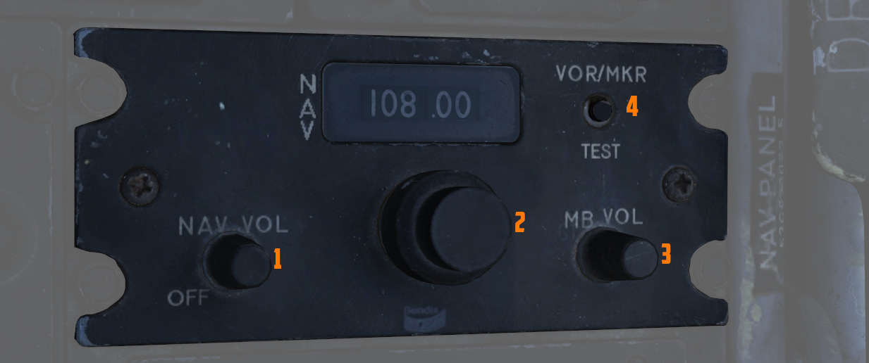
The control panel for the VOR/ILS is found on the front cockpit left console;
the panel includes a frequency indicator, two frequency select knobs (
VOR/ILS Frequency Selector Knobs
The Frequency Selector Knob (
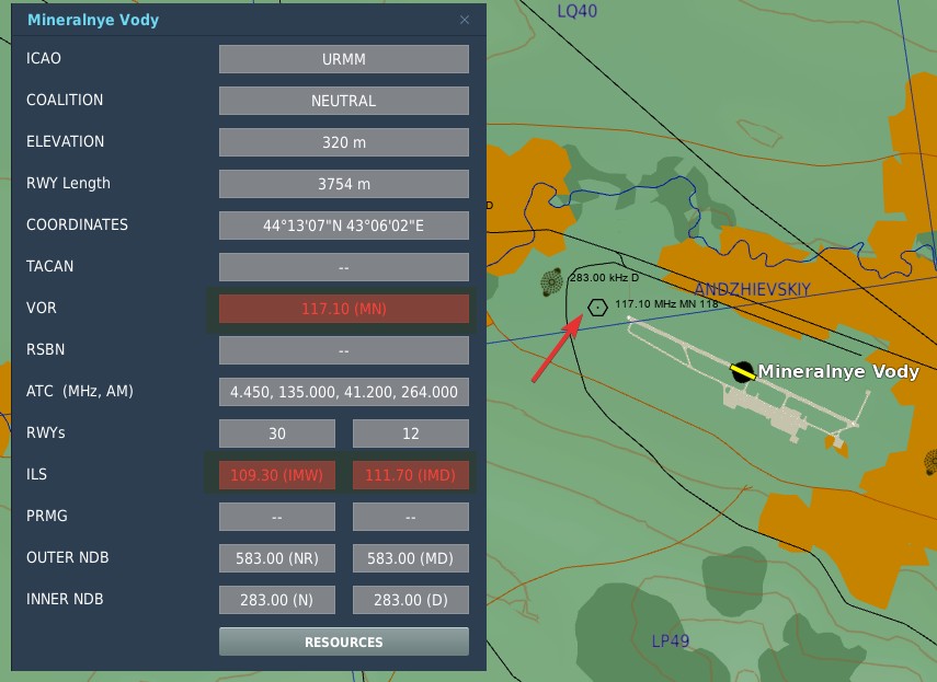
In DCS, to find the desired VOR/ILS frequency of your target, go on the Map and click an airfield that you want to fly to. If available, VOR and ILS frequencies will be listed.
💡 Not every airfield has a VOR station or an ILS systems.
The system is designed to automatically detect whether a tuned frequency corresponds to a VOR station or an ILS localizer. VOR operates within a frequency range of 108 MHz to 117.95 MHz. The ILS localizer frequency range is from 108.1 MHz to 111.95 MHz.
In the shared frequency region, VOR stations typically operate on frequencies with an even-numbered tenth of the range (e.g. 108.2 MHz, 108.4 MHz, etc.), while ILS localizer frequencies are assigned to the odd-numbered tenths, including hundredths of a MHz (e.g. 108.1 MHz, 108.3 MHz, 108.35 MHz, etc.).
The glide-slope component of the ILS operates in a frequency range from 329.3 MHz to 335.0 MHz. These frequencies are paired with their corresponding localizer frequencies, ensuring that there is no need for separate manual setting. When a localizer frequency is selected, the associated glide-slope frequency is automatically tuned, providing integrated lateral and vertical guidance (if available) for precision approaches. The Marker Beacon that works in conjunction with the ILS system, operates at a frequency of 75 MHz.
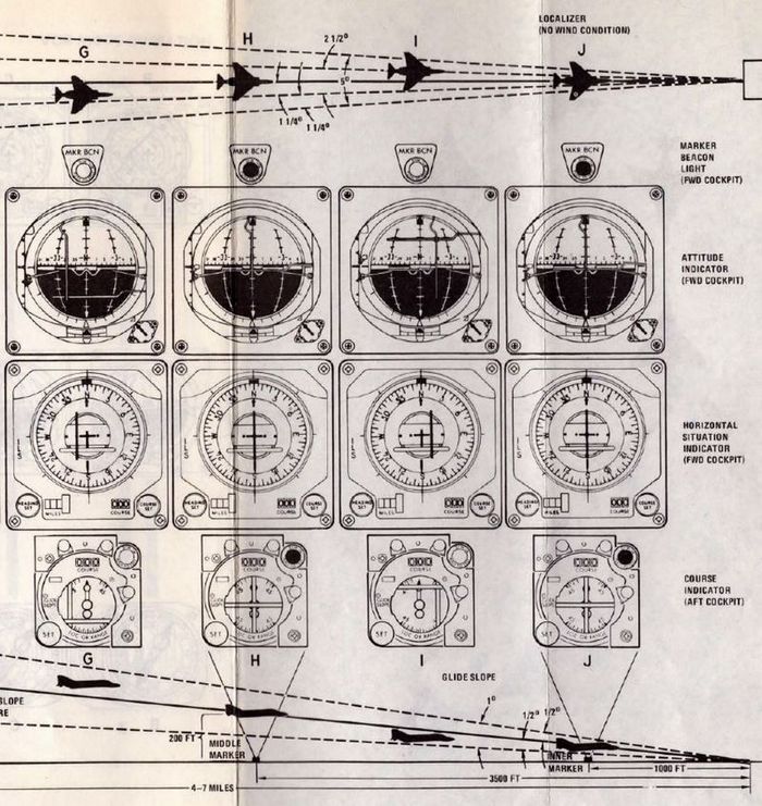
VOR/MKR Test Pushbutton
After an ILS frequency has been selected on the frequency indicator, pressing the VOR/MKR Test
pushbutton (
NAV VOL Knob and MB VOL Knob
The NAV VOL knob (
WSO Course Indicator
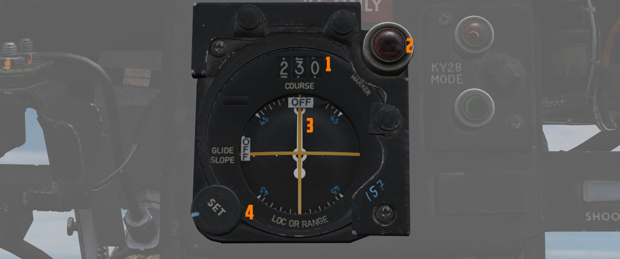
In the rear cockpit is the Course Indicator, on the main instrument panel; During an ILS approach, the indicator displays relative heading for the course set in the course selector window, as well as horizontal and vertical position relative to the ILS localizer and glide slope entered by the pilot. In this way, the WSO can assist the pilot in achieving and maintaining glide slope. The controls for the indicator are purely for the WSOs reference, and do not interact with the Flight Director Group displays in the front cockpit.
Components of the course indicator are a TO-FROM indicator (does not function with ILS), a course deviation scale, a glide slope deviation scale, a COURSE selector window, a course SET knob, a heading pointer and heading scale, a marker beacon light, a GLIDE SLOPE indicator, a course deviation indicator (LOC OR RANGE), and course and glide slope OFF warning flags.
Once the pilot has selected an ILS frequency, the WSO must set a course inbound heading in the selector window using the SET knob.
Used only with the ILS system (doesn't function with VOR).
ICS - Intercommunications System
The ICS provides normal, backup, or emergency communications between crewmembers. It also combines and amplifies audio signals received from other electronic receiving equipment (ECM, Sidewinder tone, IFF/SIF, radar altimeter, and voice radios, etc.). Identical ICS control panels are on the pilot and RIO left side consoles. The ICS consists of four amplifiers, two at each cockpit station, which permit duplex operation during normal operation. If one amplifier fails, it may be bypassed by selecting either the B/U (backup) or EMER (emergency) position on the ICS control panel. This permits continued ICS operation.
Note: If two amplifiers fail at the same station, intercommunication is impossible.
Note 2: By selecting EMER on the respective ICS control panel and using the other crewmember’s amplifier, you can listen in on audio normally only available at that station (like SW-tone or ALQ-126 PRF) but you lose the ability to control the volume of the audio you listen to.
The external interphone connection is in the nose-wheel well. When the pilot ICS switch is set to HOT MIC, ground personnel can communicate with the cockpit stations. In DCS, this works through selecting the ground crew communication menu in the DCS radio communication menu when activating ICS PTT.
| Control/Indicator | Function |
|---|---|
| Pilot Radio ICS button | ICS – Permits intercommunication when COLD MIC is selected on the function selector. Overrides UHF/VHF communications. BOTH – Keys both radios for operation. Not functional in DCS. UHF 1 – Keys ARC-159 radio for operation. UHF 2 – Keys ARC-182 radio for operation. |
| VOL control | Controls intercommunication audio level at that cockpit station. Audio level at other stations is not affected. |
| Amplifier selector | B/U – (Backup) used to bypass a fault amplifier and uses a backup output amplifier at own station. NORM – (Normal) used when all amplifiers are functioning properly. EMER – (Emergency) used to bypass faulty amplifier and makes use of input amplifier of the other station. No HOT MIC. |
| CAUTION | With the front cockpit amplifier selector switch in the EMER position, engine stall/overtemperature and Sidewinder tones will not be available to the pilot. |
| Function selector | RADIO OVERRIDE – Attenuates noncritical radio audio to emphasize intercommunication when urgent. HOT MIC – Intercommunication without keying. COLD MIC – Intercommunication only when the pilot actuates ICS keying switch on the inboard throttle or RIO actuates the keying switch on the left footrest. |
| RIO’s ICS button (Left Foot Rest) | Permits intercommunication if COLD MIC is selected on the function selector control. Overrides UHF communication. |
| RIO’s MIC button (Right Foot Rest) | Permits transmission of UHF 1 or UHF 2 radios as selected on the communications/TACAN command panel. Note that BOTH is not functional in DCS. |
Note: The two RIO footpedals have axis bindings in DCS to allow sim rudder pedals to trigger these functions.
Communications Systems
Antennas
Four VHF/UHF/L-band dual-blade antennas provide omnidirectional coverage for VHF/UHF voice, UHF data link, TACAN, and identification friend or foe/selective identification feature transponder (APX-72) operation. TACAN and VHF/UHF 2 voice communications use one set of antennas; UHF 1 voice communications, the data link, and IFF transponder use another set of antennas. Refer to the general arrangement illustration for antenna locations. The IFF interrogator (APX-76) antenna is an integral part of the AWG-9 WCS antenna.
Each individual system is connected to the appropriate portion of an upper or lower antenna through a coaxial switch and diplexer. The V/UHF 2 ANT switch on the RIO communication TACAN CMD panel must be used to select the upper or lower antenna manually; there is no automatic actuation function in these aircraft. The data link (DIL) antennas are similarly selected manually. Upper or lower antenna is selected by means of ANTENNA switches on the DATA LINK control panel. The UHF 1 voice communication ARC-159 antenna is shared with the DIL antenna system and is always on the opposite antenna from the one selected by the ANTENNA switch.
The upper V/UHF 2/TACAN antenna is the first one aft of the canopy on the turtleback, and the lower antenna is embedded in the bottom of the left ventral fin. Only one antenna is used at a time. Automatic switching between antennas prevents the loss of TACAN information. If a signal is lost or is too weak to hold receiver lockup, the TACAN automatically cycles between the two antennas every 6 seconds seeking a stronger signal.
During this cycling and search period, memory circuits retain range tracking for 8 to 12 seconds and bearing tracking for 8 seconds. The IFF antenna lobing switch is controlled by the IFF ANT switch on the RIO right outboard console. In AUTO, the lobing switch cycles the receiver-transmitter between the upper and lower antenna. In the LWR (lower) position, only the lower antenna is used to receive and transmit signals. The upper antenna pattern has a slight forward tilt; the lower pattern a slight aft tilt.
Note: In real life, it is often necessary to select LWR to improve ground station reception. However, due to the limitations of DCS, antenna switching is not modeled and thus not functional. The use of antennas is automated and/or neglected for the player. All radios and radio functions work through proper keying.
Audio Warning Signals
Audio warning signals from the weapon system are available to either or both crewmen through the ICS. Each signal has a distinct tone. A visual display accompanies most audio signals so that the flight crew can expect the tone and interpret its meaning. Most audio signals may be attenuated or turned off if not required, allowing the flight crew to concentrate on more critical tones.
Critical warning tones cannot be attenuated by any mode of ICS operation. The table below provides a glossary of audio warning signals available within the aircraft weapon systems. Approximately 1 minute of warmup is required to achieve normal operating temperature.
| Tone | Position | Controls | Function | Characteristics |
|---|---|---|---|---|
| Sidewinder | Pilot | Volume/TACAN Command Panel | Missile lock tone | High frequency, increases with lockon indication. |
| ALR-67 | Pilot & RIO | Volume/TACAN Command Panel (pilot) & Radar Warning Receiver Panel (RIO) | Threat indication | Low to high frequency, determined by threat level. |
| AN/ALQ-126 | RIO | DECM Control Panel | Threat indication | Raw PRF sound. |
| Radar Altimeter | Pilot & RIO | Radar Altimeter Indicator (Pilot) | Low altitude warning | 1 000 Hz tone, modulated at 2 pulses per second for 3 seconds. |
| TACAN | Pilot & RIO | TACAN Control Panel | Station identification | TACAN station Morse code. |
| AN/ARC-159 (UHF 1) | Pilot & RIO | UHF 1 Control Panel (Pilot) & RIO Communication/TACAN Command Panel | Own aircraft DF transmission | 1 020 Hz |
| AN/ARC-182 (V/UHF 2) | Pilot & RIO | V/UHF 2 Control Panel (RIO) & Volume/TACAN Command Panel (Pilot) | Other aircraft DF transmission | 1 020 Hz, Morse code or voice. |
| Engine Stall/Overtemperature | Pilot | None | Engine stall detection & EGT overtemp warning | Modulated 320 Hz for 10 seconds or until fault is removed if before. |
Pilot Volume/TACAN Command Panel
The Volume/TACAN command panel on the pilot left side console has three volume controls for regulating audio signals from the ALR-67, Sidewinder (SW), and V/UHF 2.
| Control/Indicator | Function |
|---|---|
| ALR-67 Volume control | Controls volume for pilot ALR-67 indication. |
| SW (Sidewinder) Volume control | Controls volume of the pilot’s Sidewinder tone. |
| V/UHF 2 Volume control | Controls volume of pilot audio from V/UHF 2 (AN/ARC-182). |
| TACAN CMD control switch/indicator | Controls and indicates crewmember in control of TACAN. |
RIO Communication/TACAN Command Panel
Allows RIO to select either UHF 1 (AN/ARC-159), V/UHF 2 (AN/ARC-182), or both radios for transmitting.
Note: BOTH is not functional in DCS.
- The V/UHF 2 ANT switch allows the selection of upper or lower antenna to minimize interference between dual UHF or data link operation. Opposite antenna selection, frequency separation greater than 55 MHz, or turning one radio off is recommended. Additionally, the DATA LINK panel provides lower or upper antenna selection for UHF 1 and DIL operation.
- The TACAN CMD push buttons provide for the transfer of TACAN control functions between pilot and RIO. The crewmember (PLT or RIO) in control illuminates when selected.
- The UHF 1 VOL control allows the RIO to adjust the audio level of the ARC 159 UHF 1 radio. The KY MODE switch is operative only when the KY-58 is installed.
Note: The Heatblur F-14 version uses the KY-28 only.
| Control/Indicator | Function |
|---|---|
| XMTR SEL switch | Selects desired VHF/UHF radio for use. UHF 1 - Selects ARC-159 UHF 1 radio. V/UHF 2 - Selects ARC-182 VHF/UHF radio. Both - Selects both radios. (Not functional in DCS) |
| V/UHF 2 ANT switch | UPR - Selects upper antenna for V/UHF 2. LWR - Selects lower antenna for V/UHF 2. |
| TACAN CMD control switch/indicator | Controls and indicates crewmember in control of TACAN. |
| UHF 1 VOL control | Controls volume of RIO audio from UHF 1 (AN/ARC-159). |
| KY MODE switch | Non-functional with KY-28. |
Loading (saving) Preset Channel(s) on UHF 1 and V/UHF 2
- MODE selection- T/R or T/R&G.
- Frequency mode control - PRESET.
- CHAN SEL switch- Select desired channel.
- Frequency mode control- READ.
- Frequency select switches - Slew to desired Frequency.
- Frequency mode control - LOAD (frequency is stored in memory for the selected channel).
- Frequency mode control- READ, Verify frequency display.
- Repeat steps 2 through 7 for subsequent channels.
AN/ARC-159 and AN/ARC-182 Remote Displays
Both the pilot and RIO have remote displays for the currently set channel or frequency of the radios. The pilot has remote displays for both UHF 1 and V/UHF 2 and the RIO only for UHF 1.
| Control/Indicator | Function |
|---|---|
| UHF 1 Remote Channel/Frequency Indicator (Pilot) | Displays a readout of the frequency or channel set for the UHF 1 radio. TEST - Initiates test for the indicator, no fault resulting in 888.888 readout. BRT - Controls display brightness. |
| V/UHF 2 Remote Channel/Frequency Indicator (Pilot) | Displays a readout of the frequency or channel set for the V/UHF 2 radio. TEST - Initiates test for the indicator, no fault resulting in 888.888 readout. BRT - Controls display brightness. |
| UHF 1 Remote Channel/Frequency Indicator (RIO) | Displays a readout of the frequency or channel set for the UHF 1 radio. TEST - Initiates test for the indicator, no fault resulting in 888.888 readout. BRT - Controls display brightness. |
AN/ARA-50 UHF Automatic Direction Finder
The UHF automatic direction finder is used with the ARC-182 radio. ADF provides relative bearings to transmitting ground stations or other aircraft. It can receive signals on any 1 of 30 preset channels or on any manually set frequency in the 108 to 399.975 MHz range. The system has a line-of-sight range, varying with altitude.
The system requires a 5-minute warmup period. During the warmup time, failure indications should be disregarded. The system uses the AS-909/ARA-48 ADF antenna. Bearing to transmitting stations is displayed on the pilot/RIO BDHI (No. 1 needle), pilot HSD, and RIO multiple display indicator. The ADF signal is interrupted during voice UHF transmissions.
AN/ARC-159 (UHF 1) Radio
The UHF 1 (ARC-159) radio provides air-to-air and air-to-surface voice communications. Radio frequency range extends from 225.000 to 399.975 MHz. The equipment allows AM mode transmission and reception on any of the 20 preset channels and a guard channel (243.000 MHz). Guard frequency may be monitored simultaneously with any other frequency selected. The ARC-159 has a possible 7,000 frequencies available by manually tuning in 25-kHz steps. The ARC-159 radio is a solid-state, self-contained unit with a minimum RF output of 10 watts. All controls for operation of the radio are on the front panel of the radio. The radio is located on the pilot left console.
Note: The UHF 1 (ARC-159) ADF position is non-functional in the modeled version of the F-14; use the DF mode of V/UHF 2 ARC-182.
| Control/Indicator | Function |
|---|---|
| VOL control | Controls volume of pilot audio for UHF 1. |
| SQL (Squelch) switch | On/off control for radio squelch (noise-blanking when carrier is not present). |
| Frequency Tuning switches | Four frequency tuning switches are used to tune the transceiver when the mode selector switch is set to MANUAL. The left switch controls the hundreds and tens digits, the second switch controls units, the third switch controls tenths, and the right switch controls hundredths and thousandths. Forward deflection of the switch increases the numeric reading, and aft deflection decreases the numeric reading. |
| FREQ/(CHAN) display | Displays frequency when the mode selector switch is in MANUAL and displays UHF channel when the mode switch is in PRESET. |
| READ switch | Deflection of the switch causes the frequency display to show the preset channel frequency. |
| BRT/TEST control | Controls brightness of radio FREQ/(CHAN) display. Turn past max to show 888.888 test display. |
| LOAD button | Depressing button saves displayed frequency to the selected preset channel. |
| Function selector | ADF – The UHF 1 ARC-159 ADF function is not functional; use the DF mode of the V/UHF 2 ARC-182. BOTH – Energizes both the main transceiver and the guard receiver. MAIN – Main transceiver is energized permitting normal transmission and reception. Receive or transmit function is selected by the microphone push-to-talk switch. OFF – Secures UHF 1 radio. |
| CHAN SEL control | Selects one of 20 preset frequency channels to use when the tuning selector switch is set to PRESET. |
| Frequency Chart | Used to record preset channel frequencies. Frequencies preset in the mission editor will be automatically displayed here in DCS. |
| Mode Selector switch | GUARD – Main transceiver is energized and shifted to guard frequency of 243.0 MHz permitting transmission and reception. In this position, both preset and manual frequency selections are not available. MANUAL – Frequency tuning controls are used to tune the main transceiver to any frequency (7,000 available) within the range of the set. The frequency selected is displayed in the readout window. In this position, PRESET selections are not available. PRESET – Used to tune the transceiver to any of 20 preset channels using the PRESET channel selector. The selected channel is displayed in the readout window. |
| TONE button | Depressing button causes a steady tone (1 020 Hz) to be transmitted on the frequency or channel selected. |
Note: UHF communication interference with the D/L may cause the TILT light to illuminate and the autopilot ACL or VEC/PCD mode to disengage. Data link interference with the UHF radios may cause audible chirping at the D/L message reply rate. Although antenna switching is not implemented in DCS, it is still recommended to use a frequency separation greater than 55 MHz, and if necessary along with turning UHF 1 or V/UHF 2 radio OFF to avoid mutual interference between UHF communications.
Note 2: Transmissions on both UHF 1 and V/UHF 2 radios, while operating on the same frequency, may result in a squeal. This feedback is a normal condition caused by RF interaction between the two radios operating on the same frequency in close proximity to each other.
AN/ARC-182 (V/UHF 2) Radio
The ARC-182 radio provides multimode, multichannel, air-to-air/air-to-surface voice and tone communications. The ARC-182 control panel is located on the RIO left console. Frequency range extends in four bands from 30 to 88, 108 to 156, 156 to 174, and 225 to 399.975 MHz on any of 11,960 channels (separated by 25 kHz).
Note: The “Have Quick” anti-jam function is not implemented in DCS.
Transmission and reception are available in AM or FM bands. The modulation is selected automatically by the radio except in the 225 to 399.975 band (toggle switch). 30 preset channels are available. Guard frequency of each band may be monitored simultaneously with any other frequency selected. The radio is used with the ARA-50 to provide automatic direction finding (ADF) to the transmitting station. The ARC-182 operates with secure-voice equipment (KY-28, the KY-58 is not implemented in DCS). Upper and lower antenna installations provide reliable line-of-sight communications to 200 NM (depending on altitude and atmospheric conditions). A remote indicator on the pilot instrument panel indicates the channel or frequency selected.
| Control/Indicator | Function |
|---|---|
| VOL control | Controls volume of RIO audio for V/UHF 2. |
| SQL (squelch) switch | On/off control for radio squelch (noise-blanking when carrier is not present). |
| Frequency Tuning switches | Four frequency tuning switches are used to tune the transceiver when the mode selector switch is set to MANUAL. The left switch controls the hundreds and tens digits, the second switch controls units, the third switch controls tenths, and the right switch controls hundredths and thousandths. Forward deflection of the switch increases the numeric reading, and aft deflection decreases the numeric reading. |
| FREQ/(CHAN) | Displays frequency when the mode selector switch is in MAN and displays V/UHF channel when mode switch is in PRESET. |
| UHF Mode switch | Operational when tuned to frequencies in the 225.000 to 399.000 MHz band. AM – Selects amplitude modulation signals. Varies with atmospheric conditions, susceptible to electromagnetic interference. FM – Selects frequency modulation signals. Reduces electromagnetic interference. |
| BRT control | Controls brightness of radio FREQ/(CHAN) display. |
| MODE selector | OFF – Secures VHF/UHF radio, unless the frequency mode switch is set to 243. T/R – Energizes transmitter and main receiver. T/R&G – Energizes transmitter, main, and guard receivers. DF – Provides automatic direction finding from 108 to 399.975 MHz. TEST – Indicates built-in-test (BIT) AT; displayed on FREQ/(CHAN) indicator. |
| Frequency Mode switch (Outer Dial) | 243 – Turns on the transceiver (takes precedence over (outer dial) operational mode control) and causes the main transceiver, and guard receiver to tune to 243.000 MHz (UHF guard frequency). All functions except VOL SQL and BAT are disabled. MAN – Allows manual selection of an operating frequency using the frequency tuning switches. The transceiver is disabled during a frequency change. G – Tunes the transceiver to the guard frequency in the band to which the radio was last tuned. PRESET – Allows selection of any one of 40 present operating frequencies with the CHAN SEL switch. The selected channel is displayed on the FREQ/(CHAN) display. Channels 31 through 40 are for Have Quick (anti-jam) use and are not implemented in DCS. READ – Displays the frequency (rather than channel) of the preset channel selected. LOAD – Automatically places the displayed frequency into the memory for the selected preset channel. |
| CHAN SEL switch (Inner Dial) | Selects one of 40 preset frequency channels to use when the tuning selector switch is set to PRESET. |
AN/ARC-182 BIT (Built-in Test)
BIT isolates faults in AN/ARC-182. BIT should be started if the FREQ/(CHAN) display blanks, indicates an erroneous readout, or the transceiver otherwise malfunctions.
Proceed as follows:
- MODE selector - TEST.
- BRT control- As Required.
- BIT requires approximately 10 seconds, observe FREQ/(CHAN) display.
- No fault is indicated by 888.888.
- Faults are indicated by a number that identifies the module or modules at fault.
| Mode | Display | Fault | Interpretation |
|---|---|---|---|
| RCV | ' | RMT or RT | Select test mode |
| XMT | ' | LOW PWR | Select test mode |
| TEST | ' | RMT CTRL | Defective control |
| TEST | 888.888 | NONE | RT and CTRL ok |
| TEST | 4 6 5 | RT | Modules 4, 5, or 6 bad |
| TEST | 0 6 1 | VSWR | RT or antenna system |
| TEST | 6 5 1 | FWD PWR | RT or antenna system |
| TEST | 1 5 7 | RT | Modules 1, 5, or 7 bad |
| TEST | 3 3 3 | RT | Module 3 bad |
TSEC/KY-28 Voice Security Equipment
The security equipment is integrated and operates with the VHF/UHF 2 and UHF 1 communication sets to enable secure voice in a hostile environment. The KY-28 control panel on the RIO left side console is the only cockpit control for operating the KY-28 in either cipher or plain-language modes.
The KY-28 has two basic modes of operation: plain (P) and cipher (C). The plain mode is used during normal UHF communications. The cipher mode is used when secure voice communications are desired. The radio sets must be ON to attain secure operation. The receiving station must be properly equipped to receive transmissions in the proper cipher mode.
| Control/Indicator | Function |
|---|---|
| ZEROIZE switch | By lifting the guard the preloaded codes are erased and must be loaded on the ground before the cipher mode can be used again. In DCS this is done via the ground crew communications menu. |
| Power-mode switch | P/OFF - UHF radio is used as a plain-language transceiver. Removes power from the system. C - Used to transmit and receive in secure mode (cipher) using preloaded codes. Also applies power to the system. To preload codes the system must be in this mode and power be applied. DELAY - Provides a time delay between PTT and actual transmission. |
| Radio-select switch | RELAY - Re-transmits information acting as a relay for other stations, increasing their range. (Not functional in DCS) RAD-2 - Selects V/UHF 2 for secure voice. RAD-1 - Selects UHF 1 for secure voice. |
KY-28 Operation
Prelaunch:
- Determine that the proper code has been set by personnel qualified in voice security equipment. In DCS and in combination with SRS (Simple Radio) this is done through the ground crew communication menu in the DCS communications menu.
- VHF/UHF radios - ON.
- Power mode switch - C.
- Radio selector - RAD-1 or RAD-2.
- If a ground test of equipment is desired, establish two-way, plain-text radio communications on the plain-voice radio with a suitable remote station and request an equipment check. (In DCS another player is needed)
- After a 2-minute warmup period, on the cipher-selected radio listen for a steady, unbroken tone in the headset followed by a double-pitched broken tone.
- Key the appropriate radio selected for transmission, hold for approximately 2 seconds, and release. The double-pitched broken tone will cease and no sound will be heard.
- Key radio and hold. A single-beep tone will be heard in approximately 1-1/2 seconds. When this tone is heard, the equipment is ready to cipher transmission.
- After the beep tone is heard, establish two-way cipher radio communications with a cooperating ground station and check for readability and signal strength.
- Set power mode and radio selector switches in accordance with the tactical situation.
Note: The above procedures may be used to perform an in-flight check of the equipment.
Postlaunch:
- The speech security equipment shall be operated as briefed.
Note: If ZEROIZE is pressed during flight, ciphered communication is not possible. The code can only be reset (or changed) through the ground crew communications menu after landing.
After Landing:
- ZEROIZE switch - ZEROIZE (as briefed).
- Power switch - OFF.
Note: If ZEROIZE has been pressed and the POWER MODE switch is in C, both crewmembers will be warned by a continuing beeping sound.
Link 4A & C Data Link
The F-14 Tomcat is equipped with the Link 4 data link system to allow for the transmission and reception of target track, waypoint information, and steering commands. Link 4 exists in two versions, the first being Link 4A which allows a surface ship or airborne AWACS to control the aircraft and also Link 4C, unique to the F-14, which is a fighter-to-fighter data link.
The Link 4A or TADIL C data link allows the F-14 to connect to a data link network controlled by a surface ship or an AWACS. The data source (or really its operator) will then provide the F-14 with target tracks, waypoints, and control commands. Additionally, it’s also used for the carrier automatic landing system (ACLS).
Link 4C, on the other hand, allows up to four F-14 Tomcats to interconnect and share target tracks to coordinate their engagements.
The system does not allow an F-14 to use both at the same time as the same transmitter and receiver are used for both A and C links. The Link 4 system itself, operates using the UHF radio band at 5,000 bits per second.
The Link 4 is controlled using the Data Link Control Panel and the Data Link Reply and Antenna Control Panel. Received control signals are displayed on the pilot VDI indicators (Vertical Display Indicator (VDI)) and the RIO DDI panel (Digital Data Indicator (DDI)).
Link 4 Controls
 The Data Link Control Panel contains the main Link 4 system power switches and the frequency selection wheels.
- The first switch controls the Link 4 built-in test and also enables the anti-jam (A-J) function, this control is currently non-functional in DCS and should be set to NORMAL.
- The frequency thumbwheels are used to set the used data link frequency, note that the first digit is set and displayed as a fixed number before the first wheel. The allowable frequency range is 300.0 MHz to 324.9 MHz.
- The third switch controls power and operational mode of the Link 4. ON turns on and enables the Link 4A data link, OFF disables the system and AUX enables the Link 4C data link.
 The Data Link Reply and Antenna Control Panel is used to select what antenna to use, own aircraft data link address, whether to transmit and which mode the Link 4A is used in.
- The ANTENNA switch sets if the data link uses the upper or lower antenna. As these are the same antennas that the UHF 1 (AN/ARC-159) uses it automatically sets that radio to the other antenna.
- The REPLY switch sets whether own aircraft replies to data link messages. NORM allows for normal operation while CANC turns off the transmitter and sets the data link to receive only.
- The MODE switch controls whether the Link 4A operates in the normal TAC (Tactical) mode or the CAINS/WAYPT (Carrier Aircraft Inertial Navigation System/Waypoint) mode. The TAC mode is the normal airborne mode while the CAINS/WAYPT mode is used while on the carrier deck to receive preflight waypoints and INS alignment data from the ship's INS system. The switch is solenoid held and spring-loaded to the TAC position, if the data link reception is lost or the power lost the switch automatically returns to the TAC mode, forcing an ongoing INS alignment to the backup handset mode. If the aircraft takes off with the switch in the CAINS/WAYPT position the weight on wheels sensor will also release it to TAC.
- The two address thumbwheel sets the least significant bits (two lowest numbers) of the aircraft data link address, the rest have to be set by the ground crew.
Link 4 in DCS
The Link 4 implementation in the Heatblur DCS F-14 implements both the Link 4A and C versions.
- To use Link 4A the data link has to be powered on, set to Link 4A mode (ON) and tuned to the correct data link frequency for the desired host which can be found on the kneeboard. On the ground and set to the CAINS/WAYPT mode the data link will receive the ME set waypoints and allow for CVA alignment if on a carrier. The frequency does not need to be set to use CAINS/WAYPT as that frequency is set with jumpers on the actual equipment by the ground crew.
- When set to TAC the data link will then receive the 8 target tracks with the highest priority from the TDS controller. The Link 4A also allows for automatic carrier landings with the data link set to use the carrier as a host.
- To use Link 4C the data link should be set to Link 4C (AUX) and be tuned to a frequency agreed upon between participating aircraft. Up to four aircraft can participate within a flight and all four aircraft should have different addresses set. As the ground crew set the two most significant bits to be the same for a flight automatically the link can only be used within the same flight currently.
- In Link 4C the participating aircraft shares up to 4 target tracks, selected by the RIO using the CAP as well as own aircraft position. The CAP also allows the RIO to update own aircraft INS position to another aircraft on the link to correlate track transmissions.
Identification Systems
AN/APX-76 IFF Interrogator
The AN/APX-76 IFF (Identification Friend or Foe) interrogator is integrated into the AN/AWG-9 operation. Then interrogator antenna itself is located on the AN/AWG-9 antenna gimbal platform.
An IFF system works by sending out an interrogation pulse and then listening for returns from cooperating transponders. In addition to the unencrypted civilian mode the AN/APX-76 is capable of interrogating in the encrypted military mode 4. This ensures that targets replying to mode 4 interrogations are indeed friendly.
The AN/APX-76 can be used both in search radar modes and in STT radar modes. To enable interrogation the IFF switch is depressed on the Detail Data Display Panel which then activates the interrogator for as long as the button is held up to 10 seconds max.
When enabled IFF received IFF returns are then overlaid on the normal AN/AWG-9 radar returns on the DDD. A friendly target will be indicated with two bars, one above and one below the normal radar return. As the AN/APX-76 is a secondary mode radar (transponder radar) apart from the AWG-9 the IFF can sometimes also detect targets not detected by the AWG-9. In this case the IFF return will not have a radar echo inside it.
In the search mode this is overlaid over each target replying and in STT over the STT target. Additionally, if the STT target is hooked on the TID the DDD will switch from normal range display to a ±10 NM display to enable display of multiple returns in case of closely grouped targets.
AA1 Control Panel
 AN/APX-76 interrogator control panel.
| No. | Control/Indicator | Function |
|---|---|---|
| 1 | M4 ALARM OVERRIDE switch | Switch disabling the mode 4 tone alarm in the RIO headset. |
| 2 | TEST-CHAL CC switch | Switch spring-loaded to center controlling IFF challenge and test. TEST - Momentary actuation, tests the AN/APX-76 by interrogating own transponder, if the same codes are set two solid lines appear on DDD at 3 and 4 miles. CHAL CC - Momentary actuation, starts a 10 second interrogation cycle only showing returns with correct mode and code on DDD. |
| 3 | CODE selector thumbwheels | Thumbwheels controlling mode and code used for interrogation. First wheel sets mode, last four set code. |
| 4 | CHAL light | Light indicating active interrogation in progress. |
| 5 | FAULT light | Light indicating fault in AN/APX-76. |
Hydraulic System
The F-14 has two separate hydraulic systems, the flight hydraulic system and the combined hydraulic system.
Both systems are driven by hydraulic pumps connected to each engine, the flight hydraulic system from the right engine and the combined hydraulic system from the left engine. Both systems are pressurized to around 3,000 psi when operating normally.
Flight control surfaces are supplied by both systems while the combined system also supplies pressure to secondary systems such as the flaps, landing gear and the refueling probe. This is so that both systems can drive the control surfaces independently from each other in case of a failure in the other.
Additionally, the hydraulic systems related to systems not necessary while airborne can be isolated by a switch next to the landing gear handle. This is so that damage to those systems won’t affect the combined system pressure and cause fluid loss. The systems that can be isolated are the landing gear, wheel brakes, anti-skid and nosewheel steering. This switch is mechanically locked to not isolating these systems by the landing gear handle when it’s in the down position.
If only one of the hydraulic pumps fail it’s possible to pressurize that system from the other pump via the hydraulic transfer pump. This pump is an omni-directional hydraulically driven pump that can supply either system from the other and will maintain a pressure between 2,400 and 2,600 psi if the driving system is at around 3,000 psi. If one system pressure falls below 500 psi the pump will be secured to prevent pump damage and preserve pressure in the working system. The pump can also be manually disengaged by the pilot.
In case of failure of both hydraulic pumps the flight hydraulic system can be driven by an electrical pump, called the emergency flight hydraulic pump. This pump is capable of independently driving the tail control surfaces, enabling the aircraft to return home and land even without pressure in either main hydraulic system. The electric pump is automatically enabled if both main systems drop below 2,100 psi and shut off if either reaches 2,400 psi again. The automatic pump activation activates the system in the low mode but it can also manually be selected to either low or high operation. The control surfaces will have a reduced deflection rate if driven by this pump, more so in low than high.
There is also a hand driven hydraulic pump that can be used to pressurize the refueling probe and wheel brake accumulator if there’s otherwise no pressure in the combined system. This is mainly for unpowered ground operation but can be used as a backup in the air.
Controls and Indicators

The HYD PRESS, hydraulic pressure indicator, contains two gauges indicating COMB, combined, and FLT, flight system hydraulic pressure in thousands of psi. The scales have markings for the nominal 3,000 psi pressure when the pumps are operating normally.
Below the gauges are flags indicating hydraulic pressure availability to the spoilers SPOIL and the operation of the EMER FLT, emergency flight hydraulic pump. The HI flag indicates on if the emergency flight hydraulic pump is operating in high and the LOW if it’s operating in low.

The BRAKE PRESSURE gauge shows available pressure in the brake accumulators. PARK indicating parking brake pressure and the AUX indicating wheel brake pressure. The green area represents a pressure from about 2,150 psi to 3,000 psi and the red a pressure below that.

The HYD TRANSFER PUMP, hydraulic transfer pump switch is located on its own panel on the pilot’s right side console. The switch allows for manual shut-off of the pump (SHUTOFF) but is normally in the NORMAL position allowing the pump to activate automatically if either hydraulic pump fails. The switch is guarded to the NORMAL position.
The emergency flight hydraulic pump is controlled by a guarded switch on the Master Test Panel. The guarded position, (AUTO)LOW allows the pump to automatically activate as detailed above and the two other positions, HIGH and LOW can manually activate those modes when the guard is up.
On the Caution - Advisory Indicator the only relevant caution light is the HYD PRESS light indicating that either main hydraulic system pressure is below 2,100 psi. It turns off when both systems are again above 2,400 psi.
Utility Systems
Oxygen System
The F-14 carries one or two 10-liter liquid oxygen bottles providing oxygen to the crew when needed.
-
Control: The oxygen supply is controlled on the pilot Oxygen-Vent Airflow Control Panel and RIO Oxygen-Vent Airflow Control Panel respectively. Both panels contain an OXYGEN switch that sets oxygen supply to ON or OFF.
-
Indicator: Liquid oxygen remaining is shown on the Liquid Oxygen Quantity Indicator on the pilot’s right side console. The gauge shows remaining liters of liquid oxygen up to 20 liters (if two bottles are installed). The indicator is electrically driven, and if it receives no power, an OFF flag will be visible, and it will display 0 liters remaining.
-
Caution light: The RIO Caution-Advisory Panel has the OXY LOW caution light which illuminates when the liquid oxygen quantity is below 2 liters.
During the INST test on the ref:MTPanel, the liquid oxygen meter shows 2 liters, and the OXY LOW caution light illuminates.
Canopy
The rear-hinged F-14 canopy is operated hydraulically and pneumatically. Controls are present in both the pilot and RIO cockpits.
See Canopy Control Handle or Canopy Control Handle for the controls.
The CANOPY caution light on both the pilot Caution - Advisory Indicator and the RIO Caution-Advisory Panel illuminates if the canopy is not in the down and locked, secured position.
Ejection System
The F-14 Tomcat is equipped with dual Martin-Baker GRU-7A rocket-assisted ejection seats, one for the pilot and one for the RIO. The ejection system is a zero/zero system, capable of successfully ejecting the crewmembers at zero airspeed, stationary, on the ground.
-
Ejection command lever: This lever, located in the RIO cockpit, selects if the RIO ejects the pilot as well when he ejects. The lever is situated beside the sensor control panel, see Eject Command Lever. When set to PILOT, the pilot ejects both crewmembers, while the RIO ejects only himself. When set to MCO, both crewmembers eject both crewmembers.
The system does not allow pilot-only ejection because it would be undesirable for the RIO to remain in the aircraft alone.
-
Indicator: The pilot has an indication of what position the ejection command lever is at on the Landing Gear Control Panel, the EJECT CMD flip-flop indicator showing PILOT when the lever is in the pilot and MCO when in MCO.
-
Canopy jettison: If the canopy does not jettison when initiating the ejection sequence, it’s possible to manually jettison it using the Canopy Jettison Handle in the pilot cockpit or the Canopy Jettison Handle in the RIO cockpit. If the canopy inhibited ejection after ejection initiation, jettisoning the canopy will most likely restart it. If ejection is needed during a flat spin, it’s also recommended to manually jettison the canopy and allow it to clear before initiating the ejection sequence as the canopy might need longer to clear during a flat spin.
Jettison System
The Jettison system has four modes of operation: emergency, ACM, selective, and auxiliary.
Emergency Jettison
The emergency jettison is selected via the EMERG STORES JETT on the Landing Gear Control Panel. Selection causes the EMERG JETT caution light to illuminate on the pilot Caution - Advisory Indicator.
- Requirement: The emergency jettison requires only no weight on wheels indicated (no master arm) and ejects all stores except for Sidewinders.
ACM Jettison
The ACM jettison is selected via the ACM JETT button under the ACM cover/switch on the Air Combat Maneuver Panel.
- Requirement: The ACM jettison, like the emergency jettison, requires no master arm but instead requires that the landing gear lever is up. Unlike the emergency jettison, the ACM jettison only ejects those stations selected by the RIO on the Armament Panel (set to SEL or B for stations 1 and 8).
Selective Jettison
The selective jettison is set and executed by the RIO on the Armament Panel. This mode of jettisoning requires the landing gear handle to be in the up position and the master arm to be on.
- Procedure: To jettison in selective mode, set the desired station switches to SEL and hold the SEL JETT switch to JETT.
Auxiliary Jettison
The auxiliary jettison mode is a backup mode to use when the other modes have failed. Like the selective jettison mode, it requires the landing gear handle to be up and the master arm to be on.
- Limitation: This mode can only eject air-to-ground stores and ejects them by actuating the normal release hooks. This means that the aircraft needs to fly straight and level as the stores are not ejected forcefully but instead just released and cleared using gravity.
Note: No jettison mode can jettison ITERs or stores loaded on those; they need to be dropped like normal, with or without the fuzes armed.
Electrical Power System
All main electrical power in the F-14 is generated from the two engine driven AC generators. The generators connected to the gearboxes on the engines are each capable of generating enough power to individually drive all aircraft systems.
As for DC power generation the F-14 has two transformer-rectifiers supplying 28 V DC, and again each one is individually capable of driving all aircraft DC appliances.
The F-14 has an external power receptacle for AC power just aft of the nosegear, capable of driving aircraft AC and DC (through the transformer-rectifiers). External power is automatically disconnected from the aircraft power system when one of the internal generators come online.
Emergency Power
The F-14 has an emergency generator driven by the combined hydraulic system generating a limited supply of AC and DC power. If the system loses main power the emergency generator takes over supply of flight critical systems within 1 second.
Controls and Indicators

The controls for the electrical systems are located on the master generator control panel.
- MASTER GEN switches: Control connection of the main generators to the electrical buses. The NORM position on the switches connect the individual generators to the buses. The OFF/RESET position disconnects the generator and also resets any protection circuits that might have cut in because of the power supply being outside normal limits. The TEST position starts the generator but do not connect it to the electrical buses making it possible to test the generator without affecting other aircraft systems. The switch is locked to the on position and needs to be lifted to move it to the OFF/RESET position from NORM.
- EMERG switch: Controls the emergency generator. In the NORM position the emergency generator is automatically connected to the essential buses if the main generators fail. The OFF/RESET position deactivates the emergency generator and also resets the associated protection circuits if tripped. The switch is guarded to the NORM position and that guard needs to be opened to move the switch to OFF/RESET.
Associated caution and advisory lights are located on the pilot Caution - Advisory Indicator. The L GEN and R GEN lights, when illuminated, indicate that the respective generator is not functioning correctly. Either because of a fault or because the engine driving the generator not running.
The TRANS/RECT advisory light indicates that only one or none of the transformer-rectifiers are functioning.
The emergency generator can be tested by selection of EMERG GEN on the MASTER TEST switch on the Master Test Panel. Completion of the test is indicated by the GO light illuminating. In case of a fault the NO GO light illuminates.
Circuit Breakers
The circuit breakers in the F-14 are located on the pilot’s right and left knee panels and behind the RIO’s seat on his left and right sides. The breakers protect aircraft systems from overcurrent by popping out and isolating the system drawing too much current. This is indicated by a white line becoming visible on the breaker as it pops out. The breaker can be reset by pushing it in and it can also be pulled out manually.
These breakers will be detailed here when implemented in DCS.
Lighting System
The F-14 Tomcat lighting system consists of the internal and the external lights.
Internal Lighting
The internal lights are the red instrument panel and console lights, red and white floodlights, and a movable utility light at both crew stations.
-
Red instrument panel and console lights: Normally used during nighttime, they back-light all instruments and controls, allowing their use while impacting night vision minimally.
-
Floodlights: Allow for additional lighting of the cockpit panels, but care should be taken to avoid affecting night vision.
-
Utility lights: Movable and can be used to illuminate a specific spot and as a map or reading light.
Controls for the internal lights are on the Master Light Control Panel in the pilot cockpit and Interior Light Control Panel in the RIO cockpit, each controlling their own cockpit lighting.
Note: The utility light function is not modeled in DCS, but the flashlight function, default keybind Left Alt + L, which moves with the cursor, can be used, providing a similar function.
External Lighting
The external lights are the position lights, the anticollision lights, the formation lights, the taxi light, the approach lights, and the refueling probe light.
-
Position lights: Located on the left wing tip (red), right wing tip (green), top aft of the left vertical stabilizer (white), and upper and lower lights on the wing gloves on each side (red on the left glove and green on the right). The glove lights are additional lights supplementing the wing tip lights. When the wings are swept forward of 25°, the wing tip lights are active, and when aft of 25°, the glove lights are active instead. With the gear down, wings forward of 25°, and the position lights in steady mode, both the glove and wingtip position lights are lit. When the anticollision lights are on, the position lights can only operate in the steady mode; otherwise, they can be set to flash.
-
Anticollision lights: Located on the chin pod or TCS pod, top front of the left vertical stabilizer, and top aft of the right vertical stabilizer. The anticollision lights are all red flashing lights. The chin pod-mounted lower light only operates while the nosegear wheel door is closed.
-
Formation lights: Dim green lights used for formation flight, which can be dimmed gradually. They are located on the aircraft nose (behind the radome), the wing tips, on the fuselage aft of the wings, and on the top edge of the vertical stabilizers. All are duplicated on both sides of the aircraft.
-
Taxi light: A fixed headlight located on the nosewheel strut. It’s automatically turned off with gear retraction if set to on.
-
Approach lights: Located on the nosewheel strut and replicate the AoA indexer for the LSOs during carrier traps.
-
Refueling probe light: Used to illuminate the refueling probe and is automatically enabled with probe extension.
All external light controls are located on the Master Light Control Panel, except for the exterior lights switch on the left throttle (see Throttle), which disables or enables all external lights apart from the approach lights.
Radar system
"I'll tell you what, it's got a fine radar inside, the APQ-120, you can get a skin paint on a skeeter 200 miles, or a stealth fighter."
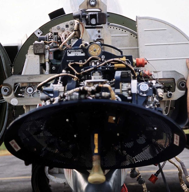 A technician works on the AN/APQ-120(V) fire control radar in the nose
of a 3rd Tactical Fighter Wing F-4E Phantom II aircraft
A technician works on the AN/APQ-120(V) fire control radar in the nose
of a 3rd Tactical Fighter Wing F-4E Phantom II aircraft
The Westinghouse AN/APQ-120 Fire Control Radar, a continuation of the F-4C's -100 and the 4D's 109, is a solid state pulse radar providing the F-4E with air to air intercept functionality, air to ground mapping, ground target reference provision to the LABS and WRCS bombing systems, as well as radar beacon capability. The APQ-120 also functions as the display system for TISEO and TV guided weapon imagery, and is integrated with the APX-80 interrogation system.
The primary conversion from the APQ-109 to APQ-120 included a reduction in the number of field replaceable units in the nose, as well as the reduction in their size; whereas the -109 had been a hybrid in its movement towards solid state hardware (primarily in the low voltage processing sections), the 120 was a fully solid-state system. While this update reduced the space overhead and weight for the system, the modification of the F-4 nose to include the M61 cannon required a reduction in antenna size, causing a marginal decrease in overall detection range. However, when taken with the increase in system reliability and reduced maintenance, the tradeoff was considered acceptable.
Starting with production of the F-4E block 60, and retrofitted to selected earlier block aircraft, was the addition of the Digital Scan Converter Group display. The inclusion of DSCG increased the overall ease of handling the APQ-120 by adding additional information on the display directly, including current radar range setting and the calculated range rate value against the current acquired target. Further, clarity of the display in all lighting conditions was improved by rendering the radar reference grids directly as part of the displayed image, rather than the previously used markings on the DVST glass. In addition, the DSCG provided the ability of the two crew members to utilize the displays independently; previously, the WSO had control over which mode both the DVST and front seat repeater display would show. With DSCG, the pilot could utilize TISEO or TV air to ground weapons while the WSO maintained a scan pattern or found a ground reference point and inserted it into the WRCS.
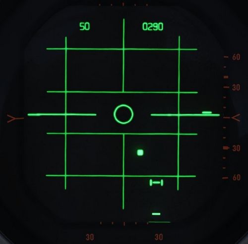
Principle
The APQ-120 is a pulse radar. The radar transmits a radio pulse focused in one direction via the antenna.
Any obstacle in that direction, for example another aircraft or simply ground, will reflect part of the energy back, which the radar then receives via the antenna to be processed and evaluated by the crew. Based on the time it took for the signal to travel back, the radar computes the distance to the obstacle.
All radar returns are then displayed on the screen based on their distance, resulting in a direct and unfiltered representation of the world in front of the aircraft.
However, since the emitter is not a perfect device, energy is transmitted into all directions, with the main focus being the direction in which the antenna is pointing at. This is referred to as the main lobe of the antenna, while any other unwanted returns from different directions are called side lobes.
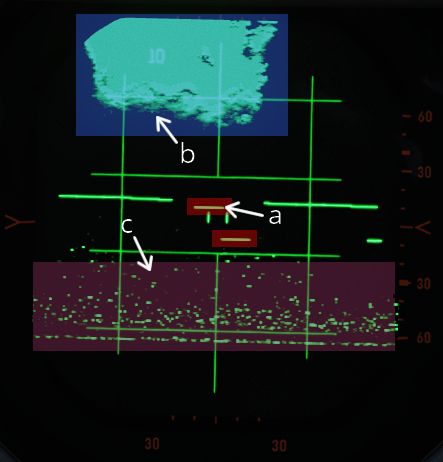
| Label | Description |
|---|---|
| a | Targets from main-lobe |
| b | Ground clutter from main-lobe |
| c | Ground clutter from side-lobes |
The same situation from outside looks as follows.
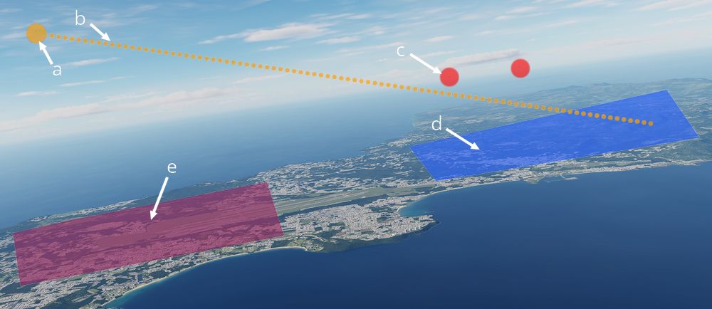
| Label | Description |
|---|---|
| a | Own aircraft |
| b | Antenna direction |
| c | Targets from main-lobe |
| d | Ground clutter from main-lobe |
| e | Ground clutter from side-lobes |
Radar Interface
The AN/AWG-9 weapons control system (WCS) is an integrated system containing the F-14’s main sensors and computer providing detection, tracking, and engagement of targets in the air-to-air and air-to-ground roles.
Detail Data Display (DDD) and Panel
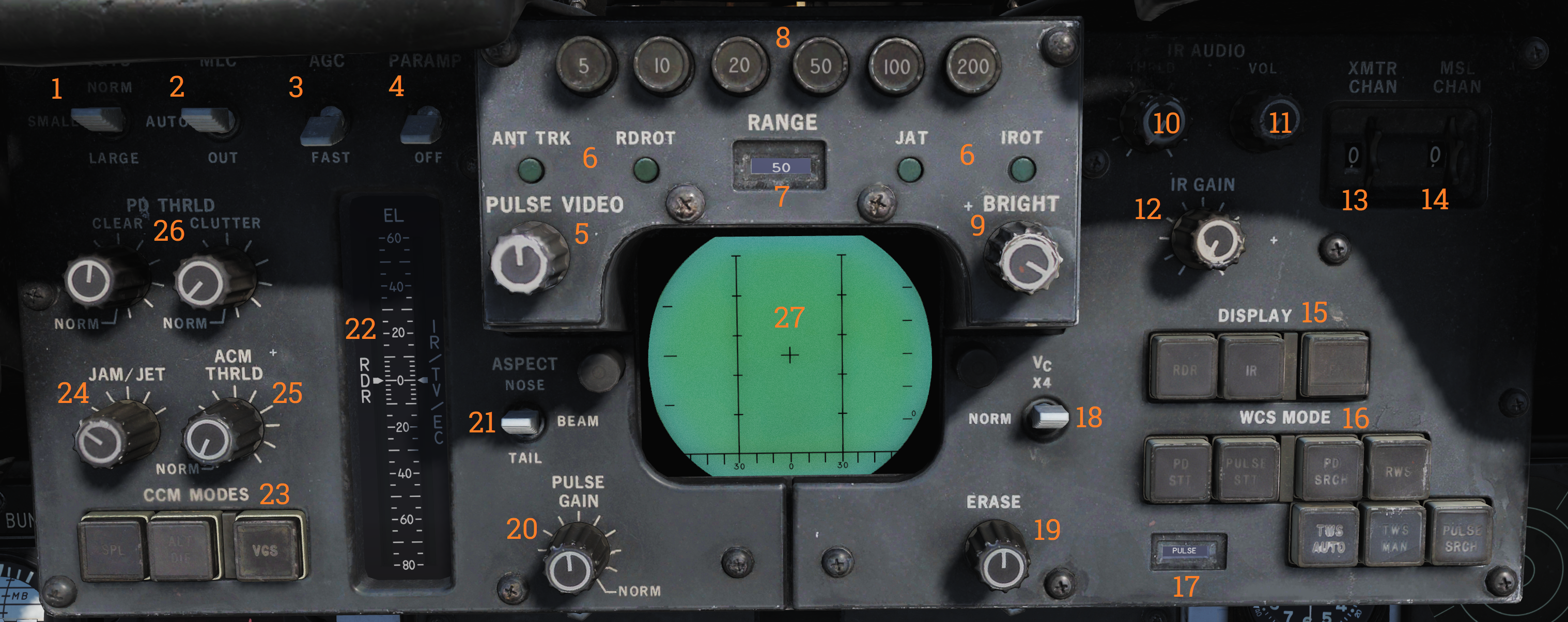
The DDD is the main control panel and display for the radar part of the AN/AWG-9 system. It contains all the controls for the radar except the scan volume and stabilization controls which are on the sensor control panel.
TGTS, MLC, AGC and PARAMP Switches
The upper left part of the DDD panel contains four switches (1-4) controling amplification, mainlobe clutter (MLC) suppression and target size parameters.
The TGTS (targets) switch selects expected target size which is used by the WCS to calculate missile launch zones and set parameters for target tracking in the radar. It also sets the range at which the missile ATC is sent, SMALL being 6NM, NORM 10NM and LARGE 13NM. The selected position of this switch might negatively affect target tracking and engagement if set incorrectly.
The MLC switch controls how the system supresses the MLC in the radar system while in pulse doppler mode. The OUT position disables the system while the IN position enables it. The AUTO position automatically enables the MLC filter if the antenna look-up angle is less than 3°.
The AGC switch controls the automatic gain control and is used in the pulse doppler modes to allow control of the time constant used for the AGC. Normally (NORM position) the AGC uses a longer time constant to calculate a mean value used for amplification. If the radar is operating in a jammed environment or heavy clutter is present the AGC can be set to use a faster time constant to mitigate these factors but this setting can also make the radar less sensitive to real targets.
The PARAMP, parametric amplifier switch allows for manual control of the parametric amplifier which is used to amplify weaker targets in all radar modes. Normally the WCS controls when to use the PARAMP depending on range but if tracking an unusually strong target it can be used to disable PARAMP to lessen the effect from background noise. If set to off manually it lessens the detection range by approximately 35%.
| Switch | Function |
|---|---|
| TGTS (targets) switch | Selects expected target size used by the WCS to calculate missile launch zones and set parameters for target tracking in the radar. Sets the range at which the missile ATC is sent: SMALL (6NM), NORM (10NM), LARGE (13NM). Incorrect setting might negatively affect target tracking and engagement. |
| MLC switch | Controls how the system suppresses the MLC in the radar system while in pulse doppler mode. OUT disables the system, IN enables it, and AUTO enables the MLC filter if the antenna look-up angle is less than 3°. |
| AGC switch | Controls the automatic gain control used in the pulse doppler modes. NORM uses a longer time constant for amplification; FAST is used in jammed or heavy clutter environments but can make the radar less sensitive to real targets. |
| PARAMP (parametric amplifier) switch | Allows manual control of the parametric amplifier to amplify weaker targets in all radar modes. Disabling PARAMP reduces detection range by approximately 35%. |
Note: AGC, PARAMP, and TGTS switches are currently not implemented.
AWG-9 Range Selection and Tracking Indication
In the upper central part of the DDD panel are located the controls and indicators for setting the radar range in the search modes. Below these are also present the indicators for radar tracking while in the single target track (STT) modes.
The six round buttons (8), which are labelled 5, 10, 20, 50, 100 and 200, are used to set desired radar range in pulse modes and IFF range, they also set the scale on the pilot target range displays. The buttons are mutually exclusive as only one range can be selected at a time. In pulse search this setting affects the PRF of the radar and the scale on the DDD and if set to 20nm or greater range it also enables pulse compression.
The range display drum (7) indicates currently displayed scale on the DDD for the pulse modes and is blank when using pulse-doppler. It can also show ±10 for when using the IFF interrogator in the STT modes.
Below these are the four radar track indicator lights which are used to indicate how the radar tracks the target in STT.
- ANT TRK: Indicates the radar is tracking the target angle (azimuth and elevation).
- RDROT: Indicates the target is in the range or rate gate.
- JAT: Indicates the antenna is tracking a jamming source’s angle.
- IROT: Indicates target angle tracking via TCS.
IR AUDIO Controls
The IR AUDIO controls (10-12) in the upper right part of the DDD panel were used with the original IR-sensor and are non-functional in modelled F-14 versions.
Radar and Missile Frequency Selectors
The thumbwheels in the upper rightmost part of the DDD panel are used to control the AN/AWG-9 radar emitter’s frequency (13) and the missile control channel used with the AIM-7 and AIM-54 (14). Adjustment of these might be needed to avoid interference from other AN/AWG-9 equipped aircraft or other external sources. The WCS reads the missile channel for the AIM-7 as the missiles are prepared as they need to be tuned and changing the channel after this will not affect a change unless the preparation sequence is restarted.
Note: Non-functional in DCS currently.
Radar Mode Selectors
In the lower right part of the DDD panel are located the controls for display mode and radar mode and its indicator drum. The display mode buttons (15) selects what mode is currently selected for display on the DDD. The RDR, radar, mode is the normally selected mode. The IR mode is non-functional as the IR system is not installed. The IFF button enables the IFF interrogator in one of its two operational modes, for more detail see the IFF section in the General design and systems overview chapter.
The radar mode buttons (16) selects the operational mode of the AN/AWG-9 radar. The two STT buttons, pulse-doppler single target track (PD STT) and pulse single target track (P STT), enables selection of an STT mode if available and relevant. These are used to automatically attempt an STT lockon onto a hooked TID target or to transfer between these two STT modes. The pulse doppler search button (PD SRCH) selects the PD SEARCH mode of the radar. The range-while-search button (RWS) selects the RWS mode of the radar. The two track-while-scan buttons (TWS AUTO and TWS MAN) selects their respective TWS modes for use in the radar. The pulse search button (PULSE SRCH) selects the pulse search mode of the radar.
The indicator drum (17) shows currently selected radar mode. Apart from TWS MAN, TWS AUTO, RWS which refers to their respective modes it can also show MRL (manual rapid lockon), A-G (air-to-ground), VSL (vertical scan lockon), OPTTRK (TCS track), PLM (pilot lockon mode), PULSE (for both pulse search and pulse STT), PD (for both pulse dopple search and PD STT) and PAL (pilot automatic lockon mode).
| Button | Function |
|---|---|
| Display mode buttons (15) | RDR, radar, mode is normally selected. IR mode is non-functional as the IR system is not installed. IFF button enables the IFF interrogator in one of its two operational modes. |
| Radar mode buttons (16) | STT buttons: PD-STT (Pulse-Doppler STT) and P-STT (Pulse STT). Search buttons: PD SRCH (pulse doppler search), RWS (range-while-search) TWS AUTO and TWS MAN (track-while-scan) PULSE SRCH (pulse search). |
Indicator drum (17):
- Shows currently selected radar mode: TWS MAN, TWS AUTO, RWS, MRL (manual rapid lockon), A-G (air-to-ground), VSL (vertical scan lockon), OPTTRK (TCS track), PLM (pilot lockon mode), PULSE (pulse search and pulse STT), PD (pulse doppler search and PD STT), and PAL (pilot automatic lockon mode).
Aspect and Vc Switches
On opposite sides of the DDD itself are located the ASPECT and VC switches. The Vc switch (18) controls the rate scale on the DDD in the pulse doppler search modes. X-4 sets the scale to 800 knots opening to 4,000 knots closing, NORM sets the scale to 200 knots opening to 1,000 knots closing and VID sets the scale to 50 knots opening to 250 knots closing.
The ASPECT switch (21) controls two different things depending on radar mode. In the pulse doppler search modes it controls the rate processing windows of the radar, NOSE sets 600 knots opening to 1,800 knots closing, BEAM sets 1,200 knots closing to 1,200 knots opening and TAIL sets 1,800 knots opening to 600 knots closing. In the short pulse STT modes the switch sets the system tracking mode to the corresponding echo edge or centroid to counteract countermeasures like chaff and specific jammer modes.
Elevation Indicator
The elevation indicator scale, EL, (22) is used to indicate the sensor elevations. The left (RDR) needle indicates current actual radar elevation. This indicator will move with the antenna in the radar search modes.
If the HCU is set to RDR the right (IR/TV/EC) needle indicates the currently set elevation center of the antenna scan pattern. This is usefull in STT as it enables the RIO to set the antenna elevation center to use when you eventually revert to search.
If the HCU is set to IR/TV the right needle instead displays current TCS elevation.
Counter-Countermeasure Mode Controls
In the lower leftmost corner are located the three counter-countermeasure mode buttons. These controls functionality to counter different jammers affecting the system. (Not currently implemented)
Radar and DDD Control Knobs
Spread out on the DDD panel are eight different knobs controlling differing functions on the DDD and radar. On the upper left side of the DDD is located the PULSE VIDEO control knob (5) which controls the video intensity on the DDD for the pulse modes. It affects only the DDD display, not the radar itself.
On the upper right side of the DDD is located the BRIGHT control knob (9) which adjusts a polarized filter which allows for mechanical control of the brightness of the DDD, mainly used in low light conditions.
On the lower left side of the DDD is located the PULSE GAIN control knob (20) which controls the radar gain in the pulse modes. This control affects the gain of the radar directly. Normally left in the detent at the fully clockwise position which allows the WCS to control it automatically.
On the lower right side of the DDD is located the ERASE control knob (19) which controls the strength of the erase beam on the DDD. The erase beam is what erases the indications continually on the DDD and thus affects how long the after-image of the detected targets will remain.
On the left side of the DDD panel are located the PD THRLD (26), JAM/JET (24) and ACM THRLD (25) control knobs. The pulse-doppler threshold knobs (PD THRLD) controls the threshold at which an echo is regarded as a contact, displayed on the DDD and tracked on the TID in RWS and TWS. The CLEAR knob controls the clear region threshold (upper half of the DDD) and the CLUTTER knob controls the clutter region (lower half of the DDD). Normally left in the clockwise NORM detents, letting the WCS automatically control them.
The JAM/JET control knob selects the threshold of what jamming intensity signal strength is needed to regard an emitter as a jammer and make it indicate a jammer strobe on the TID. The ACM THRLD sets the threshold for what to regard as a target at ACM ranges. Normally left in the counter-clockwise detent, letting the WCS automatically control it.
| Knob | Function |
|---|---|
| PULSE VIDEO (5) | Controls video intensity for pulse modes. |
| BRIGHT (9) | Adjusts brightness of the DDD. |
| PULSE GAIN (20) | Controls radar gain in pulse modes. |
| ERASE (19) | Controls the strength of the erase beam on the DDD. |
| PD THRLD (26) | Controls threshold for echo as contact in pulse-doppler modes. |
| JAM/JET (24) | Sets jamming intensity signal threshold. |
| ACM THRLD (25) | Sets threshold for target at ACM ranges. |
Note: JAM/JET and ACM THRLD not currently implemented in DCS.
Detail Data Display
| Mode | Search | STT |
|---|---|---|
| Pulse | 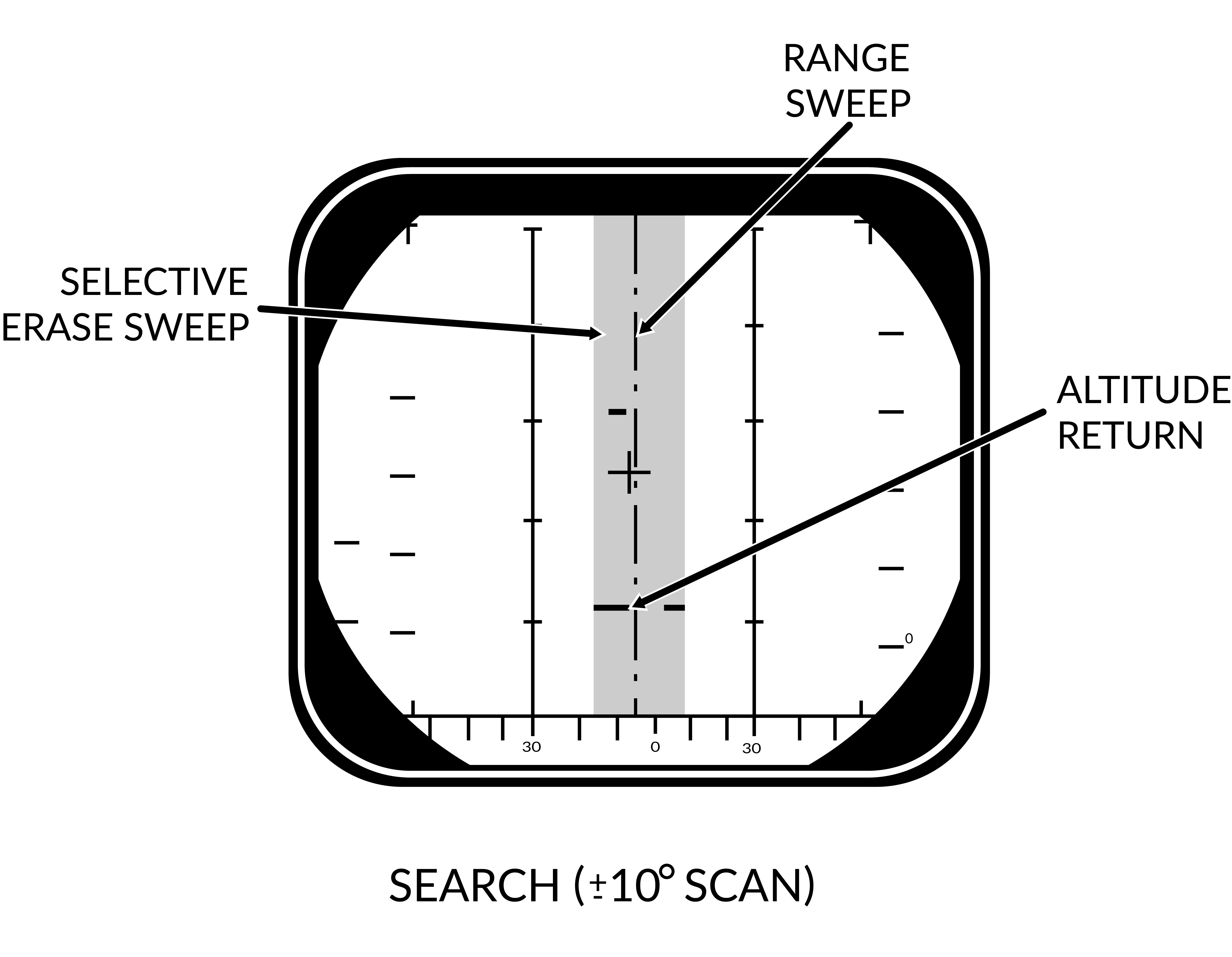 | 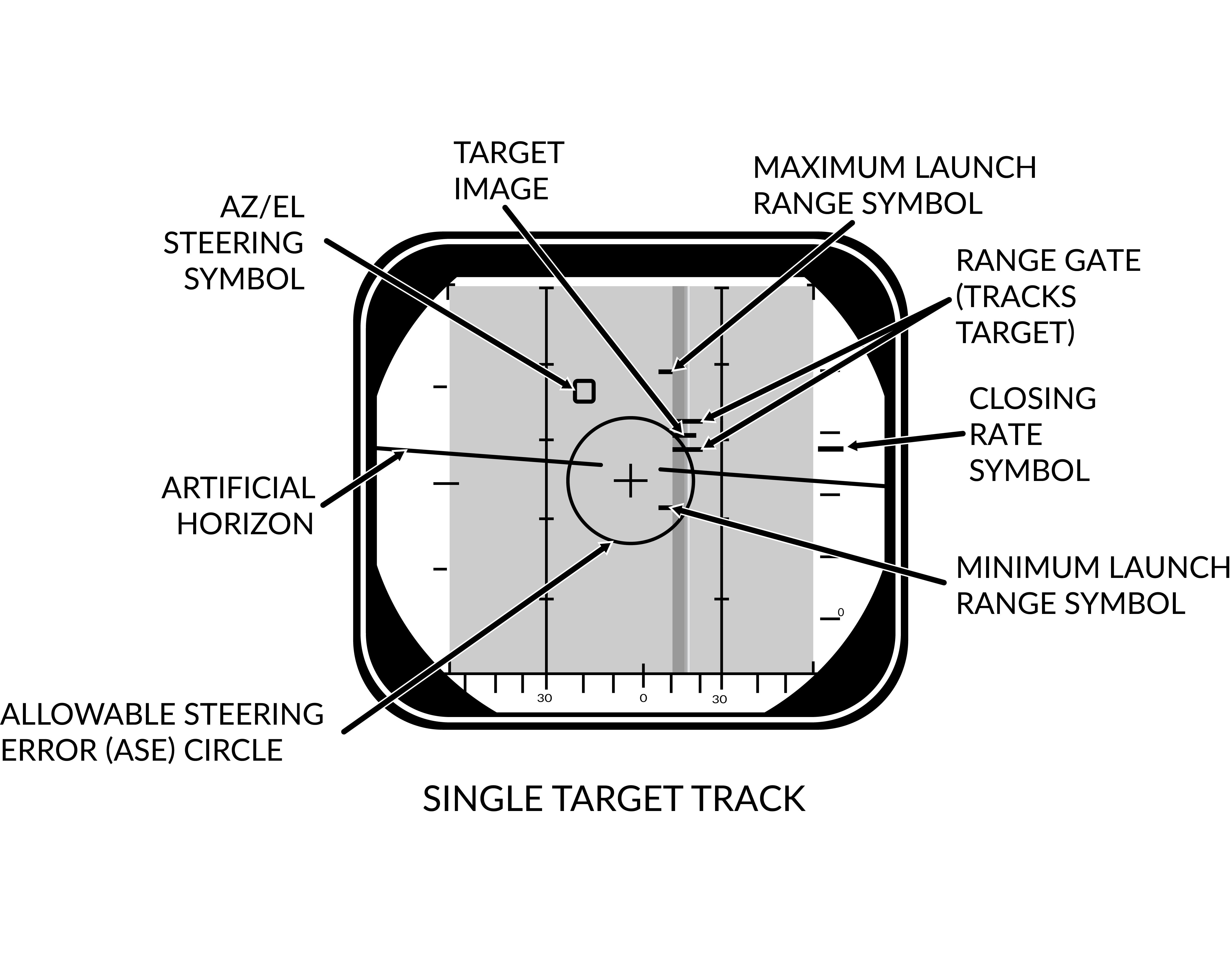 |
| Pulse-Doppler | 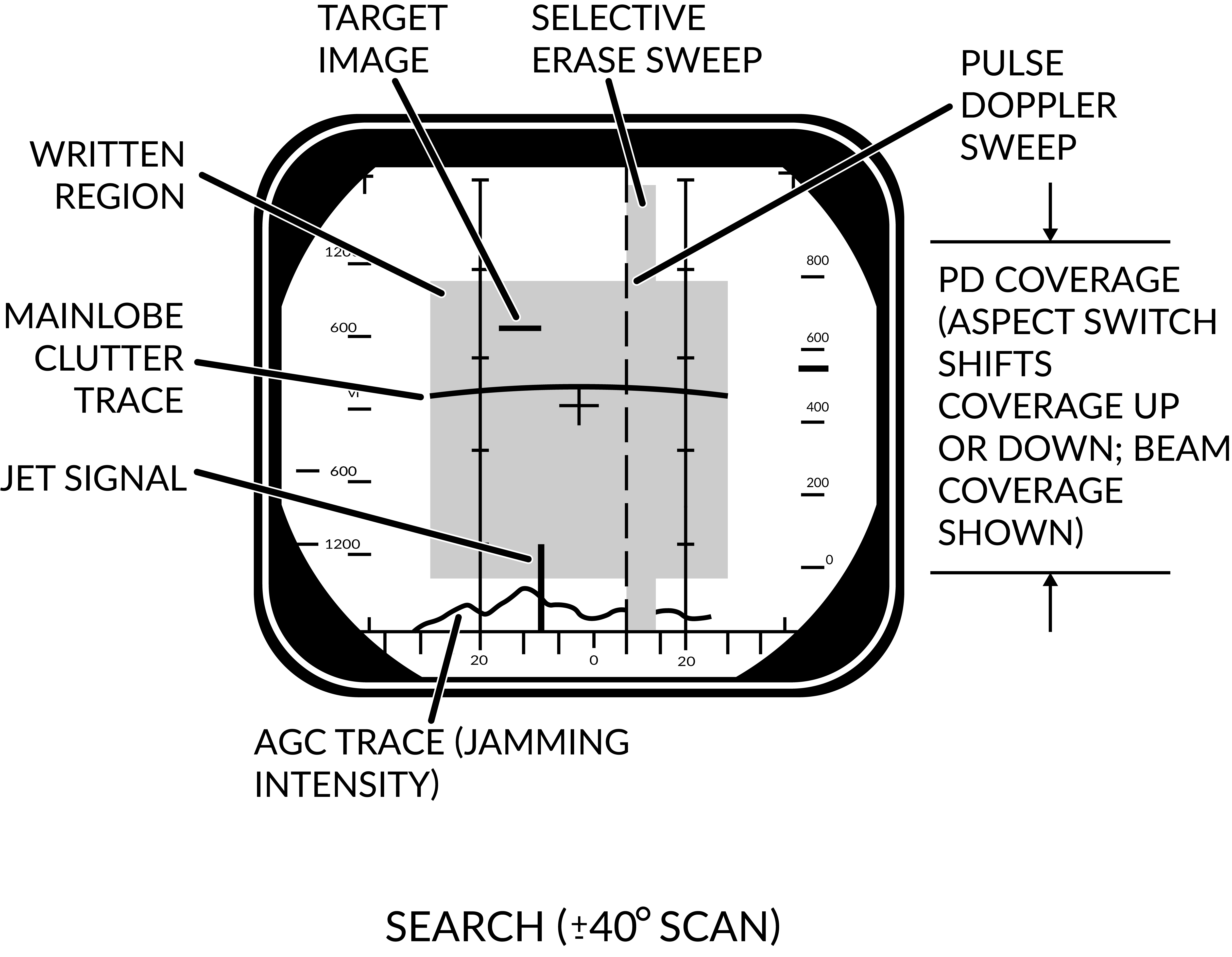 | 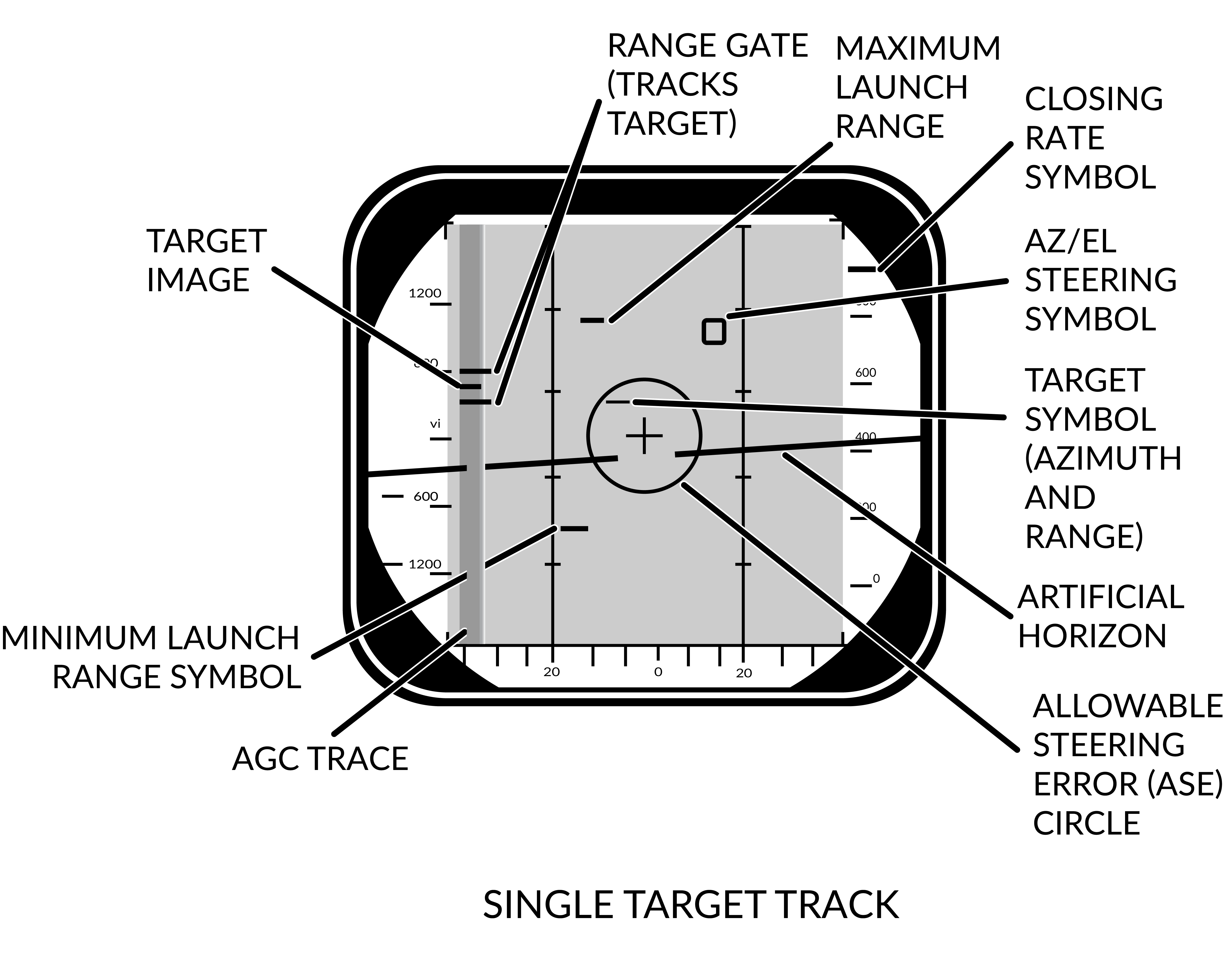 |
The DDD screen itself shows either only radar return data or radar returns combined with symbology depending on radar mode.
In the pulse search mode the display shows only radar returns and the a visual representation of the radar sweep and erase sweep. The screen shows range vs azimuth in this mode. In pulse doppler modes the AGC TRACE is added on the bottom showing supposed jamming intensity of the detected targets. The screen shows rate vs azimuth in these modes.
In the two STT modes the display shows, in addition to the return from the target, the tracking gates (either range or range rate gate), a closing rate indication on the right side and the attack symbology if in air-to-air mode and a missile is selected.
In pulse STT the target is displayed at the correct azimuth and range while in pulse doppler STT the target is shifted to the left side of the display and a generated target symbol is at the correct azimuth instead. In pulse doppler STT the AGC TRACE is added as well to give an indication of jamming strength. For information about the attack symbology see the VDIG section.
Note: AGC TRACE not yet implemented.
When the IFF interrogator is activated it superimposes the IFF information on top of the normal radar picture if in pulse search. In pulse doppler search the DDD switches to range vs azimuth at the previously set range scale while the IFF information is shown and in PD STT, if the target is hooked on the TID the DDD switches to a ±10 scale centered on the target while the IFF returns are shown.
Tactical Information Display (TID) and Associated Controls

The TID is the main data display for the WCS. It displays a tactical picture to the RIO which is used to identify and select targets for the long range weapons on the F-14 Tomcat. Think of it as a top down map showing the relative coordinates of all presented tracks and symbols, but without a representation of the ground/surface features (map). It is also used in secondary roles as a display for entering data into the WCS, for navigation, for INS alignment and for the on board checkout, OBC.
TID Display Control Knobs**:
On the upper edge of the TID are two display control knobs (2 & 4). The left one controls the contrast of the TCS display and the right one controls the overall brightness of the TID. Both settings will depend on user preference and ambient lighting.
INS and Navigational Controls**:
On the upper left corner of the TID is the status display for the INS (1), used to indicate status of the INS and its alignment.
To the sides of the TID are located two selector knobs. The one on the left side (12) controls and selects the INS or AHRS mode to use. It also allows for INS alignment.
On the right side is the selector knob (6) controlling the source used when destination steering is selected by the pilot. Selects between the different waypoints stored in the WCS. MAN position is used only for aircraft with TARPS mounted.
Adjacent to this selector is a readout drum on the upper right edge of the TID (5). It’s used to indicate the type of steering information currently displayed to the pilot.
Possible steering type shown are: destination (DEST), data link command heading (D/L), azimuth lead collision steering (LD CLSN), collision steering (CLSN), lead pursuit steering (LD PURST), pursuit steering (PURST), TACAN radial (TACAN) and manually set commanded heading (MAN).
TID Data Readout Drum
Above the TID is located the data readout indicator drum (3). It’s used to indicate the source of the data displayed on the TID text readouts. Possible readouts are: the different waypoints in the navigational system (WAY PT, ST, FIX PT, IP and HB), own aircraft (OWN A/C), first priority target (TGT 1) and SYMBOL.
Symbol indicates that the readout displays data for a hooked symbol on the TID which doesn’t have its own indicator text on the drum. The drum can also show a blank face to indicate the data source as one not having its own indicator text and which has no symbol on the TID.
TRACK HOLD and CLSN buttons
Below the selector knobs on the sides of the TID are two buttons with indicator lights, one on each side. The lights illuminates green to indicate selection.
On the left side is the TRACK HOLD button (11) which enables the track hold function. Normally targets on the TID in TWS mode are retained 14 seconds after last observation. The track hold function extends this two 2 minutes for all tracks. If disabled it reverts to the standard 14 second period, whereafter the targets will be dropped if no new observations occur.
On the right side is the CLSN button (7) enabling collision steering to currently tracked target or centroid if in TWS. This selection overrides the current steering information presented to the pilot with the collision steering, only exception being if the pilot selects the ACM.
TID Control Panel
Below the TID is the TID control panel (8). It contains 8 buttons selecting what symbology to show on the TID, these illuminates green when active. It also contains two selector knobs controlling display scale and TID mode. The buttons are:
| Control/Indicator | Function |
|---|---|
| RID DISABLE | Not implemented. |
| ALT NUM | Altitude numerals, enables display of track altitudes on the left side of track symbols. Shows a single digit representing ten-thousands of feet, 1 as an example indicating an altitude of between 5 000 and 15 000 feet. |
| SYM ELEM | Symbology elements, enables display of all supplementary symbology of tracks and waypoints. If deselected all tracks and waypoints are represented only as dots on the TID. |
| DATA LINK | Enables display of data link tracks. |
| JAM STROBE | Enables display of jam strobes on the TID. Jamming targets exceeding the JAM/JET setting on the DDD are shown if enabled. Not yet implemented. |
| NON-ATTK | Non-attack, enables or disables display of targets which aren’t possible to engage. Friendly targets being an example. |
| VEL VECTOR | Velocity vector, enables display of velocity vectors on tracks. |
| LAUNCH ZONE | Enables display of weapon launch zones depending on selected missile type. These replace the velocity vectors on relevant targets. This function is automatically enabled by the WCS 60 seconds prior to a target entering maximum launch range. |
TID Data Readouts
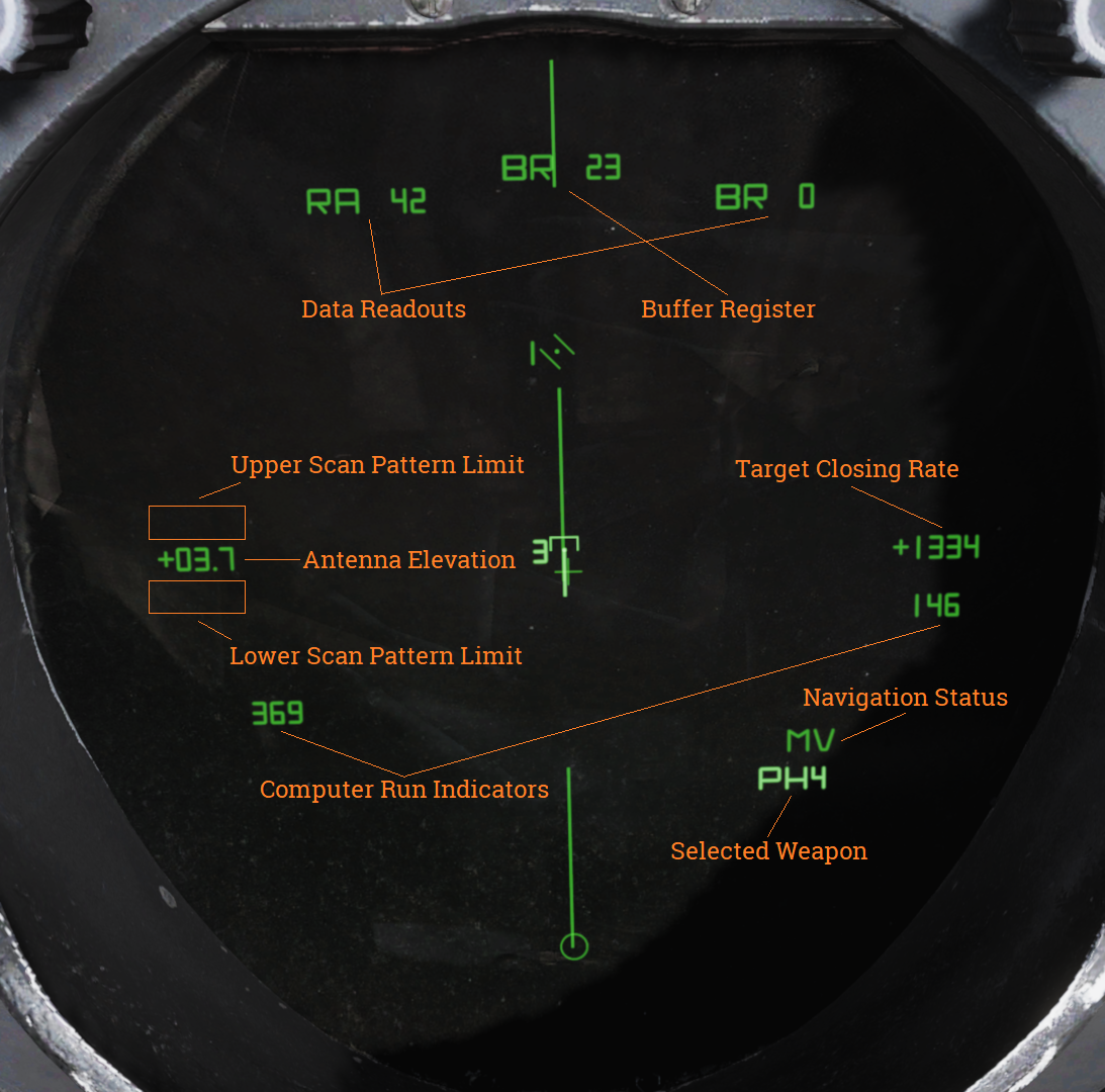
| Indicator | Function |
|---|---|
| Buffer Register | Shows data currently being entered into the WCS. |
| Data Readouts | Displays data from hooked tracks or own aircraft. |
| Computer Run Indicators | Shows WCS program cycles. |
| Antenna Elevation | Shows radar antenna elevation. |
| Scan Pattern Limits | Shows altitude limits of selected scan pattern. |
| Navigation Status | Shows status of the navigation system. |
| Target Closing Rate | Shows closing rate of STT or TWS hooked target. |
| Selected Weapon | Indicates selected air-to-air weapon. |
TID Symbology
| Element | Shape | Function |
|---|---|---|
| Center Dot |  | Marks coordinates of symbol, basic component of all symbols representing a coordinate. |
| Own Aircraft |  | Symbol representing own aircraft. Antenna scan limits, jamming strobes emanate from this symbol. Moves and has a velocity vector in ground stabilized mode. Stationary in aircraft stabilized and attack modes. If the symbol moves outside of TID presentation a line is drawn from the center of the display to the edge of the display indicating direction of the own aircraft symbol. |
| TID Cursor |  | Circle used as a hook cursor. Controlled by the HCU when in TID mode. Half-action on the HCU enables display of the symbol and also enables the HCU stick to move the cursor. The cursor location is set by stick deflection. Full-action on the HCU hooks (selects) the closest symbol if one is present within 0.125 inches of cursor center. The hooked symbol gets brighter to indicate hook. |
| TWS Steering Centroid |  | Steering centroid of TWS tracks selected by WCS for weapons engagement. |
| Unknown Onboard Sensor Target |  | Unknown sensor track in RWS, TWS, and STT modes. |
| Hostile Onboard Sensor Target |  | Track in TWS and STT modes designated as hostile by RIO. |
| Friend Onboard Sensor Target |  | Track in TWS and STT modes designated as friendly by RIO. |
| Angle-Tracked Radar Target |  | Radar target tracked only in angle (jamming target). |
| Angle-Tracked Radar Target with Altitude Difference |  | Radar target being tracked in angle only and range being computed by altitude difference ranging. |
| TCS-Angle Tracked Target |  | Target being tracked in angle by TCS. |
| TCS-Angle Tracked Target with Altitude Difference |  | Target being tracked in angle by TCS and range being computed by angle difference ranging. |
| Unknown Data Link Target |  | Data link track identified as unknown by source. |
| Hostile Data Link Target |  | Data link track identified as hostile by source. |
| Friend Data Link Target |  | Data link track identified as friendly by source. |
| Manually Entered Reference Points | ||
|---|---|---|
| Home base |  | Waypoint representing home base, carrier or airfield. |
| Waypoint |  | WCS navigational waypoint, supplanted by number indicating waypoint 1, 2 or 3. |
| Defended Point |  | Waypoint used to show area to protect. |
| Fixed Point |  | Generic fixed-point waypoint. |
| Hostile Area |  | Waypoint indicating a hostile area. |
| Surface Target |  | Waypoint indicating a surface target. |
| IP |  | Waypoint used for air-to-ground engagement, see Computer Initial Point. |
| Data Link Reference Points | ||
|---|---|---|
| Home Base |  | Data link waypoint representing home base. |
| Waypoint |  | Data link generic waypoint. |
| Data Link Fixed Point |  | Data link waypoint representing a fixed point. |
| Data Link Surface Target |  | Data link waypoint representing a surface target. |
| Position Symbol Modifiers | ||
|---|---|---|
| Mandatory Attack |  | Additional symbology on a TWS track (horizontal bar through center dot) selected as mandatory attack by the RIO. Only one target can be designated thusly and always receives an engagement priority number. |
| Data link Destroy |  | Additional symbology on a data link track (horizontal bar through center dot) designated to be destroyed by data link source. Does not affect target prioritization in WCS. |
| Do Not Attack | 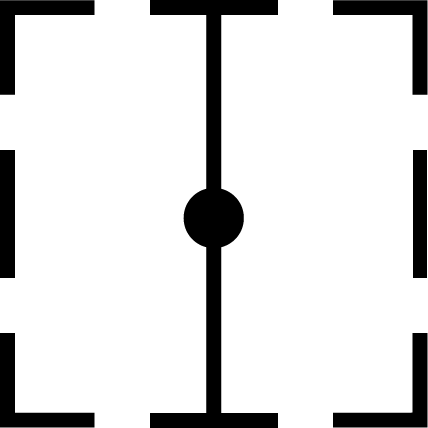 | Additional symbology on a TWS or data link track (vertical bar through center dot) designated as do not attack (by RIO) or disengage (via data link). If set by RIO removes target from WCS target prioritization. |
| Multiple Targets |  | Additional symbology on a TWS or data link track (horizontal bar on left side of symbol) indicating that the track represents multiple targets. Can be set manually by RIO or received via data link. |
| Data Link Challenge |  | Additional symbology on a data link track (small V with apex at center dot) representing data link command to visually identify target. |
| Track Extrapolated |  | Additional symbology on TWS or STT track (small X with center at center dot) indicating that no update to target has occurred within 8 seconds. Track will be deleted after 14 seconds or 2 minutes if track hold function is enabled. |
| Hooked Symbol | Symbol brightens | When a symbol is hooked by HCU or CAP functions it brightens to indicate hook. |
| Target Under Missile Attack | Symbol brightens | In TWS and STT symbols of tracks being engaged by own aircraft brightens during computed missile flight time plus 15 seconds to indicate missile engagement in progress. |
| Target in Optimum Missile Launch Zone | Symbol blinks | In TWS and STT symbols, launch zones and firing order numerics of target tracks blink when time to optimum missile range is less than 8 seconds. |
| Altitude Numerics |  | When altitude numerics are selected for display a number on the left side of the tracks indicate track altitude to nearest ten thousands of feet. The number four as an example indicates an altitude between 35,000 and 45,000 feet. Available on radar and data link tracks. |
| Firing Order Numerics |  | Indicates AIM-54 phoenix target prioritization (1 to 6) in WCS when in the TWS mode. Next missile launch will target track with number 1 and remove the number from that track to advance the other 5 track numbers one step to prepare for next launch. Mandatory attack selection on a target forces the WCS to always include that target in the prioritization. Next launch selection automatically sets hooked target as number one. |
| Time-to-Impact (TTI) |  | After AIM-54 launch the firing order number on a track is replaced with the TTI or time-to-impact indication, showing WCS calculated time until missile intercepts the target track. When the AIM-54 active command is sent the TTI numbers flash to indicate this. |
| Velocity Vector |  | Velocity vector emanating from center dot of tracks when velocity vector display is selected. Vector direction represents track heading and length represents track speed so that the max indicated speed (1,800 knots) is 1.5 inches on the TID. In TID ground stabilized mode the vector direction represents track true heading and the vector length represents track ground speed. |
| Launch Zone Vectors |  |  TUMR (Time Until Minimum Range), TUOR (Time Until Optimum Range) and TUIR (Time Until In-Range/Maximum Range). The launch zone vectors are activated manually by the RIO or when time to maximum launch range is less than 60 seconds and replaces the normal track velocity vectors. TUMR (Time Until Minimum Range), TUOR (Time Until Optimum Range) and TUIR (Time Until In-Range/Maximum Range). The launch zone vectors are activated manually by the RIO or when time to maximum launch range is less than 60 seconds and replaces the normal track velocity vectors. |
| Jamming Strobe |  | Line extending from own aircraft symbol to edge of TID to indicate a jammer exceeding the set JAM/JET threshold. |
| Radar Antenna Scan Pattern Azimuth Limits |  | The limits of the radar scan pattern in azimuth is displayed as two dashed lines extending from own aircraft symbol. Each dash and space represent 20 nautical miles each in all radar modes. In STT the two lines converge to a single tracking strobe to indicate that the antenna tracks a single target. |
| Data Link Jamming Strobe |  | Jamming strobe received via data link indicated by a line emanating from a data link point towards the jammers direction. |
| Data Link Pointer |  | Brightened cursor (circle) around a data link track used to indicate data link operator concern about the specific track. |
| Data link Priority Kill |  | Additional symbology on a data link track indicating a target that must be destroyed. Will not by itself affect WCS prioritization. |
| Artificial Horizon |  | Artificial horizon on TID representing aircraft roll and pitch. Angle of the line represents roll and vertical deflection on display represents pitch. |
| Steering Guidance Symbol |  | Symbol representing steering error from optimal missile launch direction. Should be placed by the pilot as near as possible to the center of the ASE circle and at launch should be inside of that same circle. |
| Allowable Steering Error Circle |  | ASE circle used to indicate the allowable steering error for missile launch. Size varies with attack geometry, mode and selected missile. |
| Breakaway Indication | | Large cross appearing in the center of the TID when target range is less than minimum missile launch range or gun firing range. |
Note: Some of these symbols pertain to functions not yet implemented in DCS.
Navigation Command and Control Grid (NAV GRID)
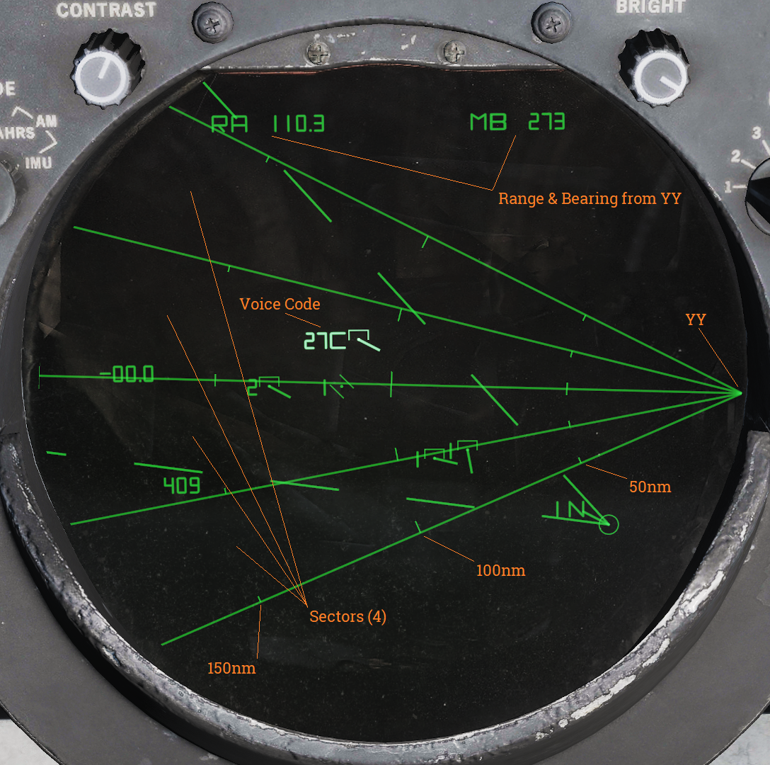
The Navigation Command and Control Grid or NAV GRID was designed to enable easy navigation and CAP control from a common fixed reference point. It enables TID readout of bearing and range from that set reference point, called YY. While NAV GRID is active displayed range and bearing on the TID for hooks and own aircraft is indicated relative YY. Additionally it also displays a grid extending from YY along a set threat axis. The purpose of the grid itself is to allow for quick position reference while a precise readout is available for a hooked target. This is where the name NAV GRID originates.
Lastly it also allows for display of something called Voice Codes. These are displayed for current hook alternating with the altitude readout on the TID if ALT NUM is selected for display. It indicates bearing from YY in tens (15 reading as 150 as an example) followed by a letter indicating range. A would indicate 0-50nm while B indicates 50-100nm and so on for consecutive letters.
The standard NAV GRID display mode is GND STAB and this allows for the grid itself to be visible. If A/C STAB or ATTK display modes are selected only the Voice Code display functionality is retained but it addition to the normal functionality the Ownship Symbol will always display its Voice Code.
As default the grid origin, YY, is positioned at the edge of the TID extending outwards along the set threat axis. The grid can be set to have between 1 and 6 sectors display, all being outlined meaning that the one sector display will have 2 lines delineating the limits and 6 having 7 lines. The size of the sectors depend on the total grid coverage, which can be up to 180 degrees, which is then divided into the selected number of sectors. Along the sector demarkation lines are drawn range indicator marks at 50nm intervals, the 50nm marks being shorter than the even 100nm markers.
The ground stab view as well as the grid can be offset as normal by the RIO via the HCU. To reset the offset, cycle to any aircraft stabilized mode and back to GND STAB.
While the original purpose of this functionality was intended for fleet defence use it works perfectly fine as a bulls-eye reference in DCS with YY set to the bulls-eye. The only real limitation being the grid only displaying along the threat axis and not all around.
Operation
NAV GRID entry:
| 1. | Set the TID MODE knob to GND STAB. | |
| 2. | Select D/L category on the CAP CATEGORY knob. | |
| 3. | Select the CAP MESSAGE button corresponding to NAV GRID. | |
| 4. | Enter grid coverage angle using the ALT/4 button on the CAP. | Press CLEAR, ALT/4 and enter desired grid coverage angle followed by ENTER. |
| 5. | Enter numbers of grid sectors using the NBR/2 button on the CAP. | Press CLEAR, NBR/2 and enter desired numbers of sectors followed by ENTER. |
| 6. | Enter YY location using the LAT/1 and LONG/6 or RNG/5 and BRG/0 CAP buttons. | Press CLEAR, LAT/1 and enter desired latitude followed by ENTER. Repeat for longitude using LONG/6 or use RNG/5 and BRG/0 instead of both for YY location referenced from own aircraft position. |
| 7. | Enter the threat axis using the HDG/8 CAP button. | Press CLEAR, HDG/8 and enter desired threat axis extending from YY followed by ENTER. |
NAV GRID exit:
- Deselect the CAP MESSAGE button corresponding to NAV GRID under the D/L category on the CAP.
NAV GRID in DCS:
When hot spawning in DCS YY will be set to mission bulls-eye for your faction and threat axis will be set from YY to first valid waypoint in the following order: HA, DP, ST, FP, 3, 2, 1 and HB or own aircraft position at spawn if none of those waypoints are present.
When cold starting with Jester he has to be commanded to adjust these parameters via the Jester wheel. He can enter YY using the same methods available for waypoints as well as entering a waypoint’s location as YY.
With a human RIO he/she will have to enter it manually.
Hand Control Unit (HCU)
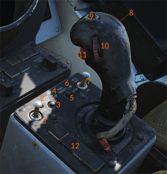
HCU Power Controls and Indicators
The controls on the HCU stick are: the action trigger switch (11), elevation vernier control (10), the OFFSET button (9) and the MRL button (8). The action trigger on the forward side of the stick has two detents, the half-action first detent and the full-action second detent. Half-action enables display of the cursor for the selected mode except when in TCS mode where it enables stick control of TCS elevation and azimuth. In the radar mode it additionally enables the super search acqusition mode in the radar (See chapter about radar transitional modes for more information). Full-action, when enabled tells the TCS to lockon to a target in the TCS mode if a target is present in its acquisition gates. In the radar mode it tells the radar to attempt lockon to a target in the radar range/rate gates at the set azimuth. In the DDD and TID modes it marks the current cursor position or, in the case of the TID mode, tries to hook a symbol if present within 0.125 inches on the display.
The elevation vernier control is a thumbwheel on the left side of the stick used in the TCS and radar modes to fine tune sensor elevation ±4° for target acquisition, this elevation deflection is added to the normal sensor elevation control. The OFFSET button on the top of the stick is used to offset any of the TID tactical displays, moving the own aircraft symbol to the TID cursor spot hook (if present) and the rest of the symbology relative to that. This function is reset and all the symbols are moved to the original positions by cycling the TID display mode selector to another mode and back. The MRL button on the right side of the stick is used to enable the manual rapid lockon mode (MRL) for target acquisition. See Manual Rapid Lockon (MRL) for more information.
The stick itself functions differently depending on selected HCU mode. In all cases the stick is only enabled with the action trigger depressed and all modes control sensor or cursor position absolutely meaning that a given deflection of the stick always moves the sensor or cursor to the same position. In the TCS mode X (up/down) controls TCS elevation and Y (left/right) controls TCS azimuth. In the radar mode X controls the range or rate of the radar acquisition gate on the DDD and Y controls the gate in azimuth in a similar fashion. In the two cursor modes X controls up/down of the cursor on the respective screen and Y controls left/right of the same.
- IR/TV overtemp indicator (2), power reset indicator (4), WCS power indicator (6).
- IR/TV switch (1): Controls power to the TCS.
- WCS XMT switch (7): Controls power to the WCS computer system and displays.
HCU Mode buttons
The four lighted buttons on the left side (12) of the HCU stick are the HCU mode buttons which illuminates green to indicate which one is active, they are mutually exclusive. The IR/TV button selects TCS mode, allowing the HCU stick and controls to control the TCS. The RDR button selects radar mode, allowing the HCU stick and controls to control the radar acquisition cursor on the DDD allowing for transition from radar search modes to STT. The DDD CURSOR button selects DDD cursor mode, allowing the HCU stick and controls to control the DDD cursor used to indicate ground coordinates when using the radar for ground mapping. This is used for radar navigational fixes or for selecting a position on the DDD radar display for use as a waypoint. The TID CURSOR button selects TID cursor mode, allowing the HCU stick and controls to control the TID cursor used to hook (select) symbology on the TID for symbology control and data readout.
- IR/TV: Selects TCS mode.
- RDR: Selects radar mode.
- DDD CURSOR: Selects DDD cursor mode.
- TID CURSOR: Selects TID cursor mode.
HCU Control Stick
The controls on the HCU stick are: the action trigger switch (11), elevation vernier control (10), the OFFSET button (9) and the MRL button (8). The action trigger on the forward side of the stick has two detents, the half-action first detent and the full-action second detent. Half-action enables display of the cursor for the selected mode except when in TCS mode where it enables stick control of TCS elevation and azimuth. In the radar mode it additionally enables the super search acqusition mode in the radar (See chapter about radar transitional modes for more information). Full-action, when enabled tells the TCS to lockon to a target in the TCS mode if a target is present in its acquisition gates. In the radar mode it tells the radar to attempt lockon to a target in the radar range/rate gates at the set azimuth. In the DDD and TID modes it marks the current cursor position or, in the case of the TID mode, tries to hook a symbol if present within 0.125 inches on the display.
The elevation vernier control is a thumbwheel on the left side of the stick used in the TCS and radar modes to fine tune sensor elevation ±4° for target acquisition, this elevation deflection is added to the normal sensor elevation control. The OFFSET button on the top of the stick is used to offset any of the TID tactical displays, moving the own aircraft symbol to the TID cursor spot hook (if present) and the rest of the symbology relative to that. This function is reset and all the symbols are moved to the original positions by cycling the TID display mode selector to another mode and back. The MRL button on the right side of the stick is used to enable the manual rapid lockon mode (MRL) for target acquisition. See Manual Rapid Lockon (MRL) for more information.
The stick itself functions differently depending on selected HCU mode. In all cases the stick is only enabled with the action trigger depressed and all modes control sensor or cursor position absolutely meaning that a given deflection of the stick always moves the sensor or cursor to the same position. In the TCS mode X (up/down) controls TCS elevation and Y (left/right) controls TCS azimuth. In the radar mode X controls the range or rate of the radar acquisition gate on the DDD and Y controls the gate in azimuth in a similar fashion. In the two cursor modes X controls up/down of the cursor on the respective screen and Y controls left/right of the same.
HCU Control Stick:
- Action trigger switch (11): Controls cursor display and super search acquisition mode.
- Elevation vernier control (10): Fine tunes sensor elevation.
- OFFSET button (9): Offsets TID tactical displays.
- MRL button (8): Enables manual rapid lockon mode.
Computer Address Panel (CAP)
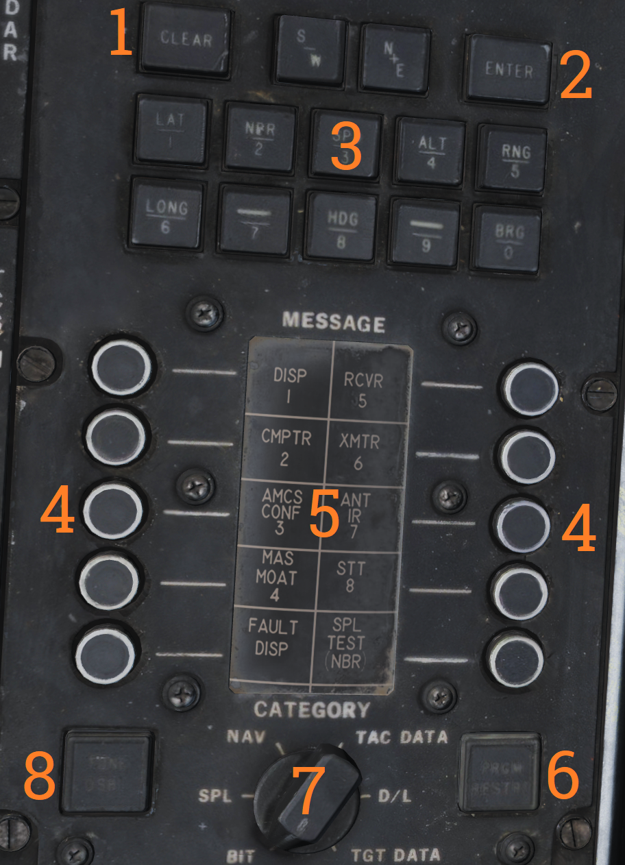
The computer address panel (CAP) is the RIO’s main interface for controlling and entering/reading data into/from the WCS computer.
Numeric Keypad (3):
The upper part of the CAP contains a numeric keypad with additional buttons for clearing input (CLEAR), entering input (ENTER) and two buttons for selecting S/W and N/E prefixes for coordinates. Some of the number keys has an additional function selecting a prefix for data display and/or entry. The keys containing functions and what those are:
| Key | Function |
|---|---|
| 1 | LAT - Latitude, selects latitude for display and entry. |
| 2 | NBR - Number, used for IFT and BITs. |
| 3 | SPD - Speed, selects speed for display and entry. |
| 4 | ALT - Altitude, selects altitude for display and entry. |
| 5 | RNG - Range, selects range for display and entry. |
| 6 | LONG - Longitude, selects longitude for display and entry. |
| 8 | HDG - Heading, selects heading for display and entry. |
| 0 | BRG - Bearing, selects bearing for display and entry. |
CAP Message Matrix Indicator Drum and buttons
The middle/lower part of the panel contains the message buttons and indicator drum and its CATEGORY selector knob. Its functionality is somewhat akin to the buttons on a MFD in a more modern system except that instead of a screen the drum is used to display the current functionality of the buttons.
The current functionality of the buttons are chosen by selecting a category on the CATEGORY selector knob, movement of the selector turns the display drum to indicate selected category’s button functionality. When a function or symbol hook is in use the corresponding message button illuminates to indicate activation.
The matrixes and corresponding functionality of the different categories are as follows:
BIT (Built in Test)
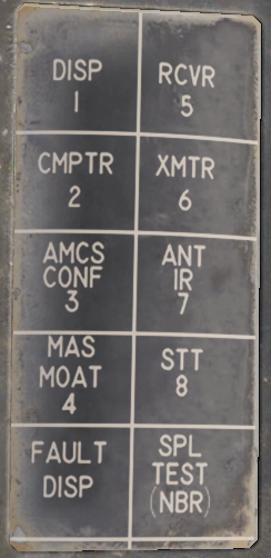 | The BIT category contains message button functions pertaining to BIT initiation of different aircraft systems. These might be functions normally run during OBC during startup or separate tests only available from here. This will be detailed in a separate chapter about on board tests and BIT when implemented, not currently implemented in this simulation. |
|---|
SPL (Special)
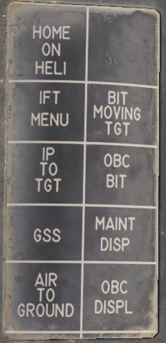 | The SPL category contains various message button functions not contained under the other categories. Currently only the IP TO TGT function is implemented and used for the Computer Initial Point air to ground mode, see Computer Initial Point. It also contains a button for manually initiating the OBC routine (OBC BIT), a button for displaying latest OBC results (MAINT DISP) and a button for clearing the latest OBC results (OBC DISPL). These and the other functions are not yet implemented. |
|---|
NAV (Navigation)
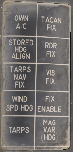 | The NAV category contains message button functions used for navigational fixes and updating data used by for INS operation and alignment. The OWN A/C (own aircraft) button selects own aircraft for data readout and entry, the same as hooking the own aircraft symbol on the TID. Its used to enter data critical for INS alignment like aircraft coordinates and altitude (and heading and speed if on a moving carrier) and can also be used for readout of the various data available about own aircraft. The STORED HDG ALIGN button is used to store and indicate if a stored heading align is available. It also allows deselection of the function resulting in a normal alignment. The WIND SPD HDG button selects entry and display of wind data, can also be used to enter wind speed and heading manually for backup navigation. The MAG VAR (HDG) button is used to display and enter magnetic variation used by the navigational system. The four FIX buttons, TACAN FIX, RDR FIX (radar), VIS FIX (visual) and FIX ENABLE are used to update aircraft position to correct for INS drift. Basic function is the selection of type of fix followed by FIX ENABLE to enter it into the system. Full procedures for these fixes can be found in the navigational section in this chapter. The two TARPS buttons are non-functional in a non TARPS aircraft. |
|---|
TAC DATA (Tactical Data)
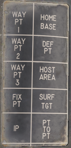 | The TAC DATA category contains message button functionality allowing for hook/selection of the different waypoints available in the WCS navigational system. The same hook can be made via HCU hook on the TID. Hooking the waypoints enables them to be updated via the CAP keypad. The PT TO PT button is non-functional. |
|---|
DATA LINK
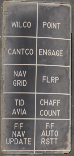 | The DATA LINK category contains message button functionality for RIO data link responses to data link controller commands. The WILCO (will comply), CANTCO (can not comply) tells the controller if own aircraft can or can not comply to a command. POINT enables the RIO to mark a hooked track sent to the controller for special attention. ENGAGE likewise indicates own intention to engage a hooked track. The NAV GRID button enables the NAV GRID functionality on the TID, see Navigation Command and Control Grid (NAV GRID). The TID AVIA button enables the AVIA display on the TID. Not yet implemented. The F/F NAV UPDATE allows for Link-4C fighter to fighter navigational updates. See the navigation chapter. Remaining buttons are non-functional. |
|---|
TARGET DATA
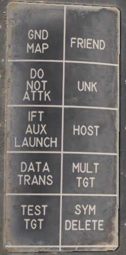 | The TARGET DATA category contains message button functionality used to modify hooked track symbols. The FRIEND, UNK (Unknown), HOST (Hostile) and MULT TGT (Multiple Target) message functions are used to mark a hooked symbol as the respective category (multiple target can be set in addition to the other three). The DO NOT ATTK button sets a target as a do not attack target, removing it from the WCS firing order. The DATA TRANS (Data Transfer) function enables a hooked jam strobe to be correlated with another hooked track symbol. This is used to allow the WCS to better use both data sources to track the target. The strobe needs to be hooked before the symbol. Currently not implemented. TEST TGT (Test Target) calls up a simulated test target in the WCS for test purposes. Currently not implemented. The SYM DELETE (Symbol Delete) allows the RIO to manually drop/remove a track or waypoint from the TID if no longer relevant. Own aircraft and data link track symbols can not be removed. IFT AUX LAUNCH and GND MAP are non-functional. |
|---|
Program Restart Button
Below the message readout and buttons are two final buttons on the panel. The PRGM RESTRT (Program Restart) button resets the currently running program in case of a computer hang-up. A computer hang-up is indicated when the computer run indicator digits on the TID stops cycling. The last button is the TUNE DSBL button which is non-functional in this F-14 version.
Data Readout/Entry Procedure
- Selection of symbol/function -> Prefix selection for display -> Data entry.
Data readout and entry on the TID always follows the following sequence: Selection of symbol/function -> Prefix selection for display -> Data entry.
Selection of desired symbol or function can be achieved either via TID hook or via the CAP MESSAGE buttons available under the different categories on the CAP DRUM.
Most data readout prefixes displays multiple readouts, as an example calling up either latitude and longitude shows both and calling up range also displays bearing and vice versa but the selected prefix is the one used for data entry.
To select another prefix for data readout without reselecting the message function the CLEAR key on the CAP is used, this resets the readout and allows for selection of a new prefix. As it’s possible that depression of a prefix button is read as a data entry if a prefix is already selected it’s normally recommended to reset using CLEAR before reselecting a new prefix. This makes the recommended sequence: Selection of symbol/function -> CLEAR -> Prefix selection for display -> Data entry.
To enter new data into selected prefix the RIO enters desired data after the prefix selection, checks it is correct and then enters it with the ENTER key. The TID readout is then updated with the new data. To clear the data without entering it, instead use the CLEAR key.
Sensor Control Panel

The sensor control panel contains the main controls for the AN/AWG-9 radar antenna scan patterns. It also contains various TCS controls, a control allowing the RIO to slave the radar to the TCS and vice versa and controls for the airborne video tape recorder (AVTR).
Antenna Search Pattern Selection
The upper half of panel contains controls for the radar antenna scan pattern. The STAB (stabilization) switch controls whether the radar antenna scan pattern is stabilized relative to the horizon (IN) or not. If in OUT instead meaning that the scan pattern is relative to the F-14 aircraft armament datum line (ADL). The WCS computer can override this setting if necessary. The AZ CTR (azimuth control) and EL CTR (elevation control) knobs sets the elevation and azimuth centerpoint of the antenna scan pattern. The azimuth control moves the azimuth scan center within 65° degrees of the aircraft centerline, this is disabled if azimuth scan width is set to ±65° as it already scans the whole available azimuth range. Do not move the scan pattern so that it scans outside of 65° from aircraft centerline as this might damage the antenna as it might hit the antenna azimuth stops. The elevation control moves the elevation position of the bottom bar of the elevation scan pattern relative to zero elevation. It can move from -76° to +54°. Both control knobs have marked centerpoints, being aircraft centerline and zero elevation respectively.
The AZ SCAN (azimuth scan) and EL BARS (elevation bars) selector knobs controls the size of the antenna scan pattern. The AZ SCAN selector knob has four settings, ±10°, ±20°, ±40° and ±65°. The EL BARS selector knob also has four settings, 1, 2, 4 or 8 bars. 1 bar being 2.3°, 2 bars 3.6°, 4 bars 6.3° and 8 bars 11.5°. The reason for the elevation coverage not equalling one bar times the number of bars being that the bars overlap slightly.
The last radar control on the panel is the VSL switch. Momentary selection of VSL HIGH or LOW activates the vertical scan lockon acquisition mode (VSL). (See Vertical Scan Lockon (VSL))
TCS Controls
On the right side of the panel the SLAVE switch controls which sensor is slaved to the other or none slaved at all. In the center position the sensors move individually from each other. In RDR the radar is slaved to the TCS line of sight while a TCS track is present. In TCS the TCS is slaved to the radar line of sight if a an STT or JAT exists. Both modes can be used to allow a sensor to guide a sensor to lock onto whatever the other sensor is currently tracking.
The TCS TRIM knobs controls TCS calibration in azimuth (AZ) and elevation (EL). This is used to calibrate the TCS line of sight to be equal to the radar line of sight. Normally this is done by locking a target in STT, setting slave to TCS and then fine-tuning the calibration knobs until the TCS looks directly at the locked target.
The last two switches controlling the TCS are the ACQ (acquisition) and FOV (field of view) switches. The ACQ switch controls how the TCS locks onto targets. AUTO SRCH means the TCS will move by itself in a limited search pattern trying to find a target. MAN (manual) means the TCS only locks onto targets if commanded to by the HCU in TCS mode and AUTO means the TCS automatically tries to lock onto targets entering its field of view. The FOV switch sets whether the WIDE or NAR (narrow) field of view is used by the TCS.
The lower part of the panel contains controls for the airborne video tape recorder (AVTR) controlling and indicating power mode and time remaining on tape. This is currently not modelled in DCS.
General Radar Operation
The AN/AWG-9 radar in the F-14 is an all-weather, multi-mode pulse doppler radar using the X-band (X-band being 8-12 GHz). It was designed specifically to be a long range radar system capable of guiding up to 6 AIM-54 Phoenix missiles using its track while scan mode. One originally envisioned scenario was its use as a long range fleet defender intercepting russian bombers and attack aircraft threatening the fleet. During the F-14’s later service life this mission transitioned more towards the anti-fighter side, a mission for which it was very well adapted.
The AN/AWG-9 radar has two basic operational modes, pulse and pulse doppler, each with its own pros and cons. Below is a table listing function, weapons capability, expected range and target data available.
| Mode | Function | Weapons capability | Detection-range |
|---|---|---|---|
| Pulse | |||
| Pulse Search | Medium range search and detection, secondary air-to-ground. | Boresight missiles. | 60nm |
| Pulse STT | Short to medium range single target track and missile launch. | Gun and missiles, AIM-7 in CW and AIM-54 in active launch. | 50nm |
| Pulse Doppler | |||
| Pulse Doppler Search | Long range search and detection. | Boresight missiles. | 110nm |
| Range While Search | Long range search, detection and ranging. | Boresight missiles. | 90nm |
| Track While Search | Long range search, detection, multiple target track and missile guidance. | AIM-54, multiple target capability. | 90nm |
| Pulse Doppler STT | Long range single target track and missile guidance. | Gun and all missiles. AIM-7 in PD and CW and AIM-54 in PD and active. | 90nm |
Detection-range approximation for a 5m²-target.
Pulse Mode
In the pulse mode of operation the AN/AWG-9 does not use pulse doppler filtering which means that it can be used to detect targets at all aspects and also be used for rudimentary ground mapping. On the pro side this means that the radar in this mode cannot be notched as it does not need to have a relative speed to register the target. The downside however is that the radar does not have an easy way of differentiate between unwanted ground reflections and real targets meaning that aircraft can hide in the ground clutter near the ground. Because of this and the increased difficulty from trying to differentiate real targets from the general background noise without doppler filtering means that the range in the pulse modes are less than in the pulse doppler modes.
The radar has two pulse modes, pulse search and pulse single target track (P-STT).
Pulse Search
Pulse search is used to search for and find airborne targets at range.
It is possible to use this radar mode as a basic ground mapper as well which can be useful for navigation and navigational fixes and can also be used in a pinch to detect larger surface targets like ships. Keep in mind though that the radar is not built with this as its main function and that a real air-to-ground radar will outperform it handily.
In this mode the radar cannot by itself differentiate targets and generate tracks meaning that the WCS will not generate track files and display anything on the TID. This also means that pulse search is not capable of guiding missiles.
The DDD in this mode will display a radar image indicating the azimuth and range of targets at selected scale and it is possible to transition to P STT using the RDR mode with the HCU stick. It is possible to select ground or aircraft stabilized modes of operation using the STAB switch on the sensor control panel.
Pulse Single Target Track (P STT)
Pulse STT is used to track a single target, like pulse search mode it is not susceptible to notching but it is to ground clutter. The fact that the STT modes use gates to track the target, in this case range gates, means that it is less susceptible to ground clutter but a target close enough to the ground that the ground return enters the range gates would be likely to shake the lock.
As it is only in the pulse doppler modes that the missile guidance commands can be sent pulse STT is limited to launching AIM-7s in CW mode and AIM-54s in active launch mode limiting their ranges. At short ranges, ACM ranges, it is possible to use the ASPECT switch to set what aspect of the target to track, this is just to counter different types of countermeasures. As an example, if set to NOSE the radar will be less susceptible to chaff as the radar weights its track towards the targets leading edge (nose) away from the chaff being launched behind the target.
A successful track is indicated by the ANT TRK and RDROT indicator lights on the DDD, meaning that the antenna is tracking the target and that the target is within the range gates. If the target is jamming with sufficient strength, negating a range track, the radar will transition to a jam angle track instead, indicated by the JAT indicator light on the DDD illuminating instead of the RDROT. When range tracking is again possible at closer ranges the radar will transition to that instead.
The DDD in this mode will be similar to the pulse search mode but the antenna will be locked onto the target and not scan. Additionally the DDD will show the range gates around the target, a closing rate symbol at the right scale and applicable attack symbology if a valid missile is selected.
Pulse Doppler Mode
In pulse doppler mode the AN/AWG-9 uses doppler filters to filter out unwanted returns, enhancing target detection and thus increasing detection range. The pros of this mode being that, as said, targets can be detected at greater ranges, ground returns mostly eliminated and missile guidance commands be sent to AIM-7 and AIM-54 missiles. The AIM-54 both in TWS and STT and the AIM-7 in STT only. The biggest con of this mode being that it is susceptible to notching as a target returning zero relative speed will be filtered out.
The pulse doppler modes of the AN/AWG-9 are, pulse doppler search, range while search, track while scan and pulse doppler STT. The three search modes have a common DDD display, the main difference being that pulse doppler search has a slightly better range as the other two modes need to process FM-ranging to enable range indication of tracked targets.
Pulse Doppler Search
The DDD in the pulse doppler search modes displays returns at azimuth versus rate (closing speed) meaning that by reading only the DDD the RIO can only discern target closing speed and azimuth. The display indicates observed closure rate vs the ground (with own airspeed subtracted) as opposed to relative closure rate. While this means that a target directly ahead, moving directly towards the radar, will show true target airspeed this speed varies with target aspect and radar antenna azimuth. This reason for this is that the radar itself only reads relative airspeed which is then modified by subtracting own airspeed for display on the DDD.
At the bottom edge of the DDD the AGC-trace is displayed indicating radar return intensity enabling the RIO to discern jamming targets by their return strength. The jamming targets are shown as jamming strobes on the TID if they exceed the set jamming threshold (set by the JAM/JET knob on the DDD).
The scale shown on the DDD (what rate region is shown) can be set by the Vc switch on the DDD panel. X-4 sets the scale to 800 knots opening to 4 000 knots closing, NORM sets the scale to 200 knots opening to 1 000 knots closing and VID sets the scale to 50 knots opening to 250 knots closing. The operating range of the doppler filters can also be configured by the ASPECT switch on the same panel, NOSE sets 600 knots opening to 1 800 knots closing, BEAM sets 1200 knots closing to 1200 knots opening and TAIL sets 1 800 knots opening to 600 knots closing. This allows the RIO to optimize the doppler filters for a known target closing speed and this affects the whole radar processing unlike the Vc switch which only affects the DDD.
Because of the way the radar operates the doppler filters it will have two blind ranges. The main lobe clutter (MLC) region which contains most of the ground returns, including those returning with zero groundspeed and is 266 knots wide, centered around own aircraft groundspeed (133 knots slower and 133 knots faster). This is the reason that the radar can be notched as a target with the same relative groundspeed as the ground will also be filtered out. This is however only true for look-down conditions as when the radar antenna looks up into the sky this filter isn’t necessary and can be turned off. If the MLC switch on the DDD panel is in AUTO the radar will automatically turn off the MLC filter if looking more than 3 degrees above the horizon. It can also be turned off manually by the RIO but if the antenna looks down this can make the displays unusable in RWS and TWS as all of the ground returns will be sent to the computer for tracking. In whichever case, with the MLC filter off, the target cannot notch the AN/AWG-9 if it is above the radar.
The second filter, and second blind spot, of the radar is the zero doppler filter. This blind area is centered around a closure rate of negative own groundspeed, meaning a target moving away from own aircraft at the same speed as own aircraft. This blind area is a hardware limitation as it is a doppler radar mode it cannot detect targets without a doppler shift. The resulting blind area is 200 knots wide, meaning that a chased target moving at a speed of within 100 knots (+/-) of own groundspeed will be invisible to the radar. This means that when chasing a fleeing target it may very well be necessary to use the pulse modes instead.
Both filters vary with azimuth as own airspeed relative to target varies with aspect. Relative airspeed from a target at 45° will be less than a target at 0° as own speed vector will be pointing away from it slightly. This is the reason for the mainlobe clutter trace presenting a curve on the DDD as the observed speed of the returning ground returns will vary with azimuth.
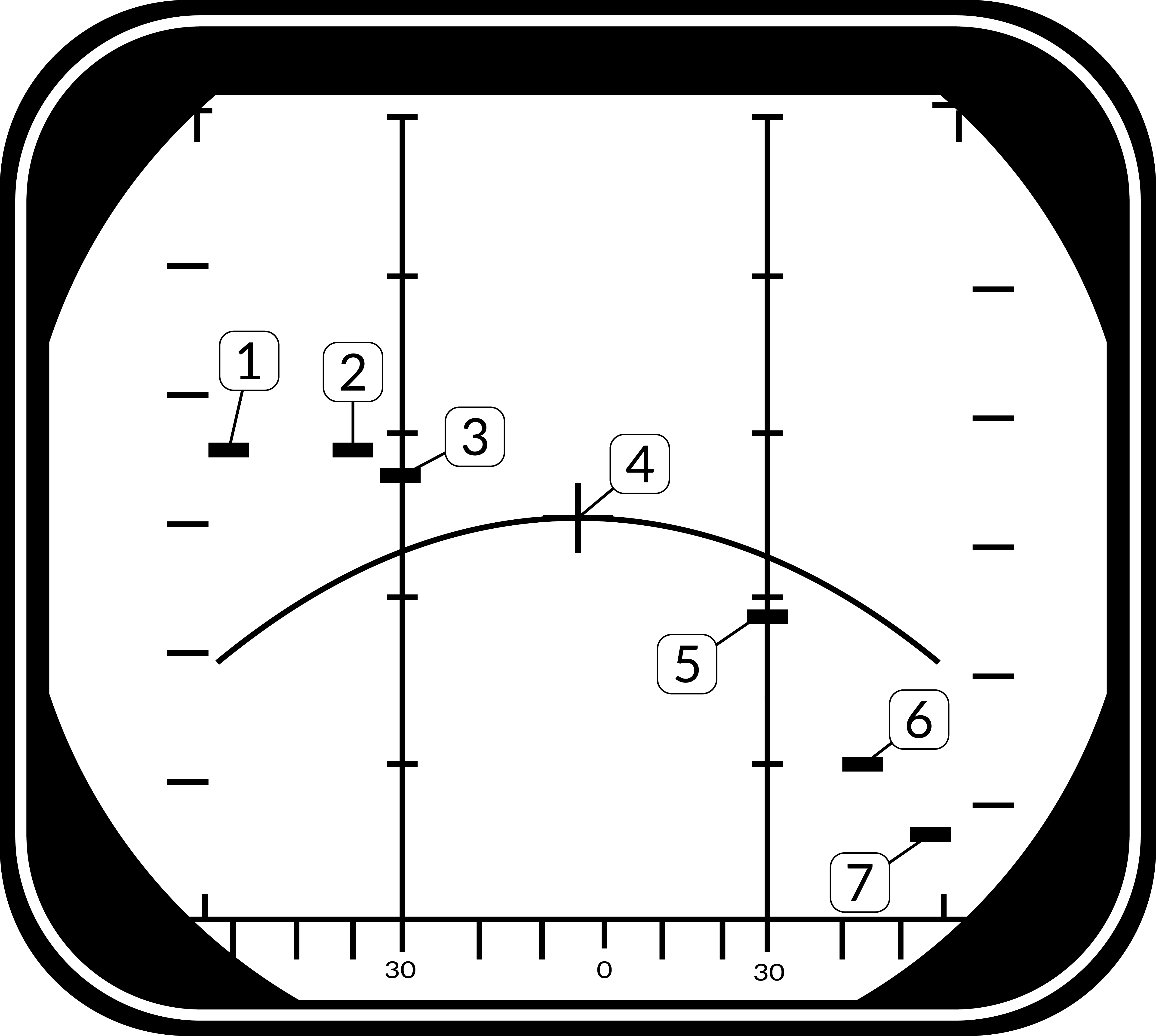
Target groundspeed 900 knots, own airspeed 1200 knots. See table below for details, line of sight rate is the sum of target and own aircraft relative rate.
| Look Angle | Line of Sight Rate | Target Heading |
|---|---|---|
| 60° | 1490 | 180° |
| 45° | 1500 | 120° |
| 30° | 1428 | 100° |
| 0° | 1200 | 90° |
| 30° | 672 | 80° |
| 45° | 210 | 60° |
| 60° | -300 | 0° |
Note: Position 4 has the target in a flanking or “notching” position making it disappear inside the MLC filter or MLC ground return. In a look-up situation with the MLC filter disabled the target would still be visible.
Additionally, all pulse doppler search modes use ground stabilization exclusively and thus the STAB switch is inoperative.
Pulse Doppler Search
The pulse doppler search mode is used mainly as a kind of early warning mode. It is the search mode with the greatest detection range but it can display no range to the RIO, only closure rate. For this reason, the TID can display no track information.
Range While Search (RWS)
In range while search a frequency measuring ranging mode is added (FM ranging) to allow the radar to measure range of tracked targets in addition to closure rate. This additional processing does however mean that the effective range of the radar is somewhat lesser. The display on the DDD is the same as in pulse doppler search, the TID however also shows tracks in this mode showing the targets as tracks momentarily as they’re scanned and displaying their position and altitude. The targets are shown for a maximum of two seconds or until the antenna again scans the same bar at the same azimuth at which time it is removed unless detected again. Maximum number of concurrently shown tracks are 48.
Track While Scan (TWS)
The track while scan mode uses the same FM ranging as RWS with the same reduction in range compared to pulse doppler search and the DDD display is also the same. The main difference that the computer establishes track files and tracks up to 24 targets concurrently of which 18 can be shown on the TID at any given time.
As the computer routine calculating these tracks need a set track refresh time of 2 seconds this limits available azimuth scan area and bar settings to either 20° 4 bars or 40° 2 bars. When entering TWS the computer automatically selects the ±20° 4 bar scan disregarding the RIO set scan volumes unless those are set to ±40° 2 bars in which case that is used instead.
The TWS mode is also the only mode enabling guidance of the AIM-54 at multiple targets (up to six), and as soon as engagable targets are detected the computer starts assigning them a missile priority number according to optimal missile firing sequence.
The TWS has two submodes available, TWS Auto and TWS Manual, which one is used is selected by the RIO with the corresponding button on the DDD panel. What differs between the two is that in TWS auto the computer takes control of used scan volume and scan pattern azimuth and elevation as soon as target tracks are present. The WCS computer automatically tries to optimise the scan volume and direction so that tracking of the prioritized targets is maximised. If not selected before launch the WCS overrides as soon as the first AIM-54 is launched and selects TWS Auto.
In TWS the pilot is guided to the computed centroid of the tracked targets via the navigational cues and this centroid is also displayed on the TID as a small x-shaped cross.
For additional information about TWS symbology and missile guidance see TWS and TID Symbology.
Pulse Doppler Single Target Track (PD STT)
The pulse doppler STT works and looks much like the pulse STT mode. It does however have the same advantages and disadvantages compared to pulse STT as the other pulse doppler modes compared to the pulse modes. This means that while much better at tracking a target close to the ground it is however vulnerable to notching.
The DDD display for pulse doppler STT looks like pulse STT display except that the target return and antenna azimuth display is moved to the left side of the screen and a generated synthetic target marker is displayed at the correct azimuth instead. This is so that the targets range can be displayed by the synthetic target unlike the other pulse doppler modes which only shows closure rate. The other symbology on the DDD in this mode are the same as in pulse STT.
Unlike in pulse STT however the AN/AWG-9 can send missile guidance commands in pulse doppler STT enabling launch of AIM-7 and AIM-54 in pulse doppler mode. This is the mode with the greatest launch ranges for those missiles with the disadvantage, in the case of the AIM-54, of only being able to engage one target at a time.
Transitional Modes
The transitional modes are the ones used to transition into the single target tracks from the search modes, ACM modes, via TCS or between the two STT modes.
HCU Stick in Radar Mode
When using the AN/AWG-9 radar in the different search modes it’s possible to manually use the HCU stick with radar mode selected to select a target on the DDD for STT lock.
Pressing the HCU trigger to half-action while in radar mode displays the acquisition gates on the DDD and enables the supersearch mode in the radar. In supersearch mode the antenna does a ±10° search pattern at the selected amount of bars around the acquisition gates.
The acquisition gates can then be steered over the detected position of the target with the HCU, left/right used to steer azimuth and up/down used to steer range or rate depending on if pulse or pulse doppler is used. The antenna elevation is then fine-tuned using the elevation vernier on the HCU until the target return is visible within the acquisition gates. At that time the RIO can then select full-action on the HCU trigger, commanding the radar to attempt a lockon at the commanded azimuth, range/rate and elevation.
If successfully executed the radar then transitions into the respective STT mode and the correct indicators on the DDD illuminates. Pulse STT is used if transitioning from pulse search and pulse doppler STT if transitioning from any of the pulse doppler search modes.
TWS STT Acquisition
In TWS it is possible to attempt an STT lockon by hooking a track on the TID and then selecting either pulse STT or pulse doppler STT on the DDD panel. The WCS computer then commands the antenna in supersearch to the hooked tracks azimuth, range/rate and elevation and attempts a lockon if a target is detected.
Unlike in a manual HCU acquisition this process is completely automated but its success rate is also less than a manual transition.
ACM Modes
The AN/AWG-9 has three distinct ACM acquisition modes. Pilot lockon mode (PLM), vertical scan lockon (VSL) and manual rapid lockon (MRL).
The ACM modes are listed in priority order, the different modes overriding other modes lower in the prioritization. This means that PLM always overrides VSL and lower modes and VSL overrides PAL and lower modes but not PLM and so on.
All of the modes can be exited by the RIO selecting half-action and release on the HCU except PLM which will be in effect until the pilot releases the PLM button.
Pilot Lockon Mode (PLM)
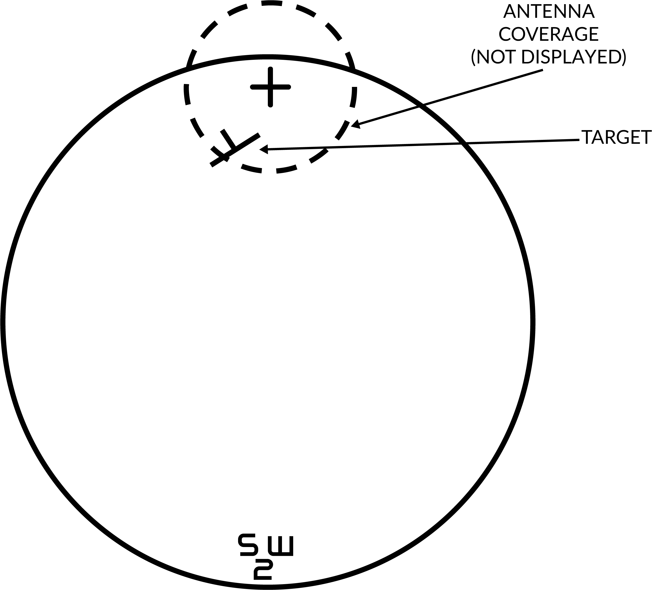
The PLM is the ACM mode with the highest priority, it always overrides any other radar mode and is enabled when the pilot presses the PLM button on the front of the right throttle. Depression of that button commands the antenna to the armament datum line (ADL) and causes it to lock onto the first target seen out to 5 NM.
Thus the procedure to use PLM is for the pilot to fly the ADL marker on the HUD over the target and then press and hold the PLM button until lockon occurs. The PLM continues until a target is detected and transition to pulse STT occurs or the PLM button is released making the radar transition to pulse search instead.
Vertical Scan Lockon (VSL)
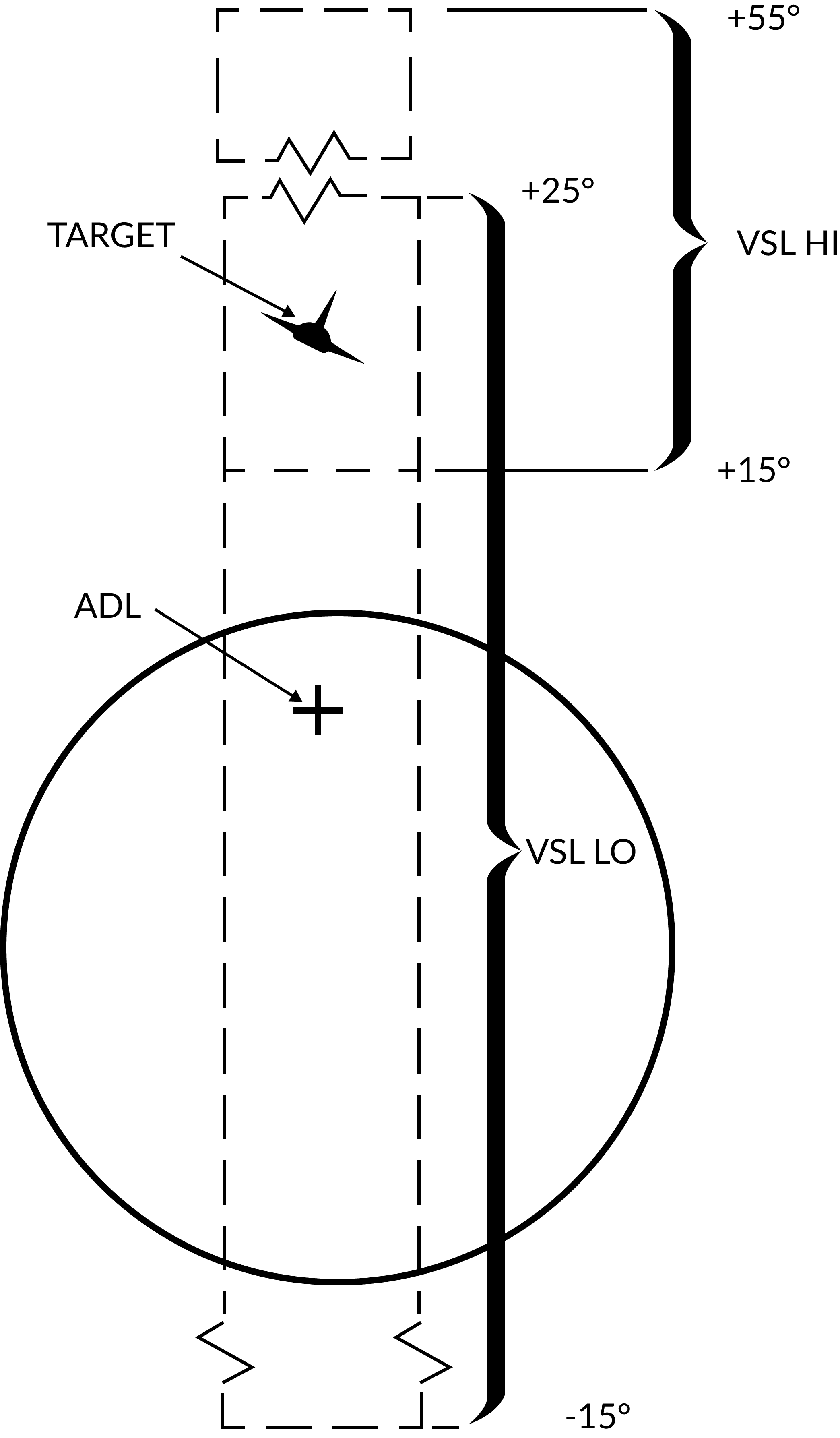
The VSL mode is enabled by the pilot or the RIO and is used to acquire a target at own aircraft's current heading from an elevation of -15° to +55°. The RIO can use the VSL switch on the sensor control panel in the RIO cockpit. Two submodes are available by placing the switch into either VSL HI (high) or VSL LO (low) and releasing it back to center. The pilot can enable VSL HI or LO by selecting UP or DN respectively on the target designate switch when not in A/G mode.
This commands the antenna to start a volume 5° wide in a circular fashion. If VSL HI is commanded the vertical area covered is from +15° to +55° and if VSL LO is commanded the area covered is from -15° to +25°. VSL is indicated on the HUD by the diamond moving with antenna line of sight indicating its current position.
When a target is detected within 5 NM the radar transitions into pulse STT, otherwise it continues in VSL until another mode is selected.
Pilot Automatic Lockon (PAL)
PAL is enabled by the pilot selecting DES on the target designate switch when not in A/G mode.
PAL commands the antenna to an 8-bar ±20° scan pattern locking onto the first target detected out to 15 NM. This mode is indicated by the diamond on the HUD following current antenna line of sight.
Manual Rapid Lockon (MRL)
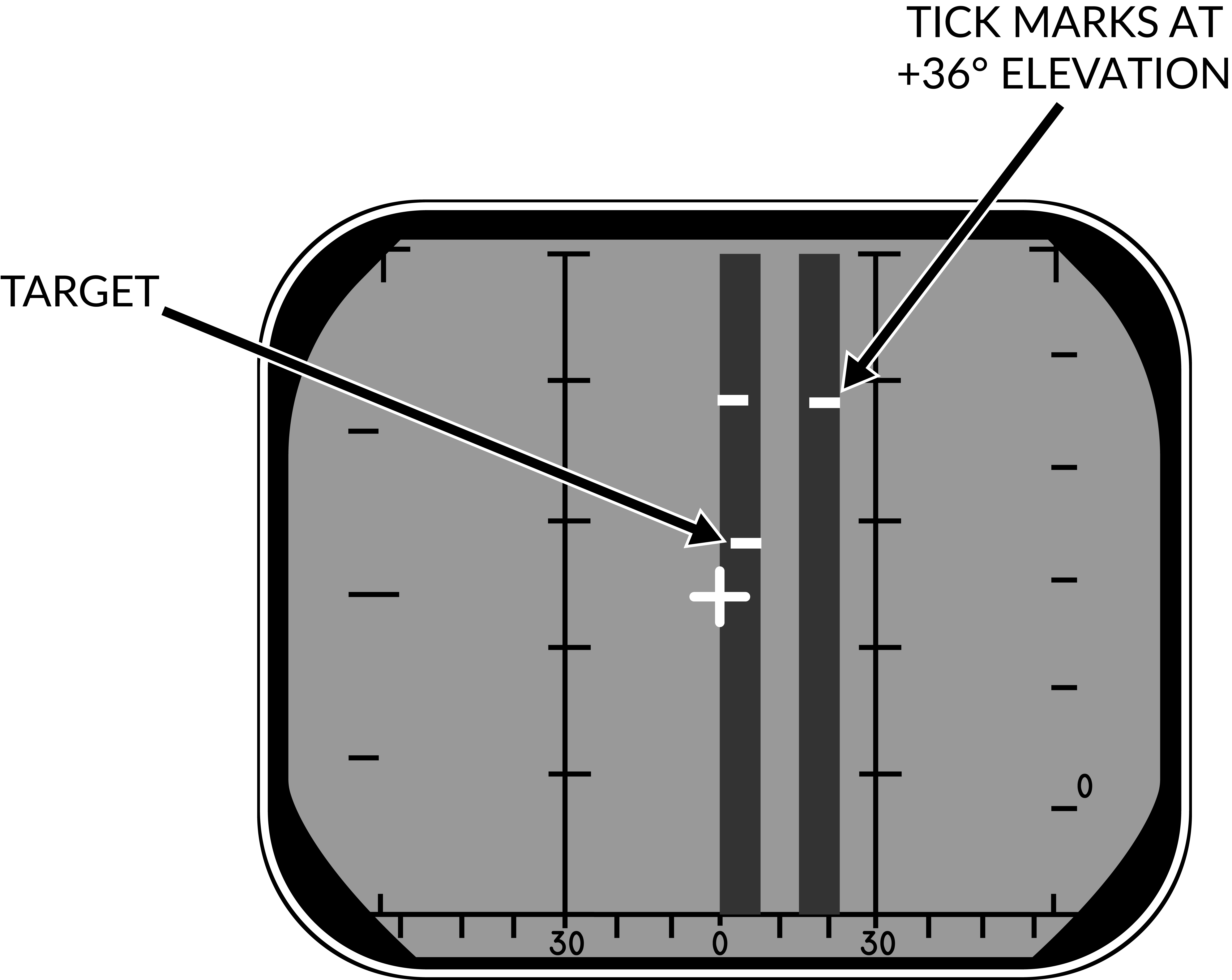
The manual rapid lockon (MRL) mode allows the RIO to quickly acquire a target within the antenna limits out to 5 NM. When the MRL button on the right side of the HCU stick is depressed it commands the radar to start a one-bar supersearch pattern out to 5 NM.
The HCU stick controls the supersearch pattern in azimuth and elevation (left/right controlling azimuth and up/down controlling elevation). The DDD displays a normal supersearch pattern in 5 NM scale and additionally two tick marks are shown at the edge of the scan pattern indicating current elevation.
When the target is visible the RIO commands full-action to acquire the target and transfer to pulse STT. If only half-action is commanded after entering into MRL and then released the radar transfers back to pulse search.
TCS Slave Radar Acquisition
The TCS can be used to track a target in angle while still using the radar for range and rate. When selecting the radar to be slaved to the TCS line of sight via the sensor control panel (SLAVE in the RDR position) the radar will still be active but pointing in the direction of the TCS line of sight while the TCS has an active track instead of scanning.
From this state it is possible to command half-action and then position the acquisition gates at the target video and then command full-action. This will result in either pulse doppler slaved or pulse slaved mode depending on previous radar mode. It is also possible to switch using the P STT and PD STT button on the DDD panel.
The resulting submode entered is equivalent to an STT mode where the TCS is instead used to track the target's angle rather than the radar itself. The radar is still used to track range and rate, on the DDD the IROT lights instead of the ANT ROT, IROT relating to IR tracking which has been replaced by the TCS in the modeled F-14 versions.
This mode can be used to guide missiles, active and CW modes if in pulse and in PD if in pulse doppler. If the SLAVE switch is set to INDEP from this mode the system reverts to true pulse STT or pulse doppler STT depending on current mode.
Transition Between the Two STT Modes
If necessary it is possible to transition between pulse STT and pulse doppler STT by pressing the corresponding button. If the transition fails the radar reverts to the respective search mode of the commanded STT mode (pulse search if pulse STT was selected and vice versa).
Transition Back to Search
If the RIO wishes to transition back to a search mode he commands half-action and releases it causing the radar to return to pulse search if in pulse STT and pulse doppler search if in pulse doppler STT.
If the radar loses target lock in STT and cannot reacquire it reverts to the respective search mode as when the RIO transitions manually via half-action.
VSL and MRL can also be reset and returned to search the same way but PLM being prioritized means that the only way to deselect PLM is either target lockon and transition to pulse STT or the pilot selecting the PLM button again telling the radar to return to pulse search.
AN/AXX-1 TCS General Operation
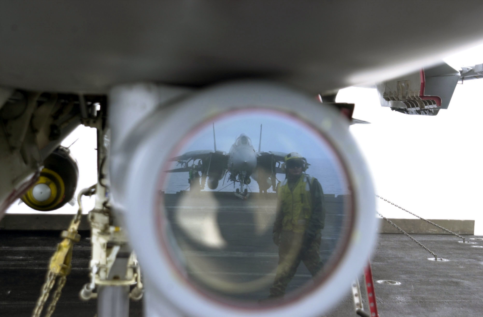 U.S. Navy photo by Photographer’s Mate Airman Justin S. Osborne. (030418-N-0382O-591)
The television camera set, or TCS, was constructed as a replacement for the IRST which was present in the first F-14As produced. When the IRST was found to have insufficient capability it was decided to replace it with the TCS giving the F-14 a long range visual identification capability.
The TCS is located underneath and behind the radar radome, just in front of the nose gear well. It contains an aircraft stabilized high resolution (for its time) closed circuit television camera. The sensor has two fields of view (FOV), narrow (NFOV) which is 0.44° or 10X magnification and wide (WFOV) which is 1.42° or 4X magnification. The gimbal limits are +/- 15° except upwards which is limited to +11° and the TCS is capable of independent contrast lock or being slaved to the AN/AWG-9 radar.
The TCS is controlled by the RIO using the sensor control panel, DDD, TID and the HCU. Video from the sensor can be displayed on the TID and the VDI in the front seat. Also, the video can be recorded using the airborne video tape recorder for later review. (Not currently implemented in DCS.)
TCS Controls and Symbology
The controls for the TCS are located in the RIO cockpit at the sensor control panel, the DDD and the HCU/TID. The pilot display control panel contains a switch allowing display of TCS video on the VDI.
Sensor Control Panel
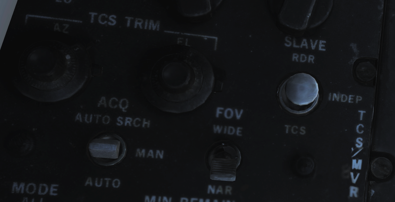
The controls on the sensor control panel for the TCS are; the TCS trim knobs, the SLAVE switch, the field of view, FOV, switch and the acquire, ACQ, switch.
The TCS TRIM knobs control TCS sensor line of sight, LOS, calibration relative to the AN/AWG-9 radar LOS. If needed these can be used to trim the TCS so that the two sensors LOS correlate. They have a ±2° range of motion and the easiest way to check and calibrate the TCS is to lock up a friendly target in STT and adjust the knobs until the TCS LOS is correctly aimed at the locked target.
The SLAVE switch controls which sensor is controlled by the other. If set to RDR the radar is slaved to the TCS as long as an optical track exists. If set to INDEP each sensor operates independently of the other. And if set to TCS the TCS is slaved to radar LOS as long as an STT track exists.
The FOV, field of view switch controls what FOV is used in the TCS. WIDE sets the 1.42°, 4X magnification FOV and NAR sets the narrow 0.44°, 10X magnification FOV.
Lastly the ACQ, acquire switch controls the acquisition mode in use in the TCS. AUTO SRCH enables an automatic acquisition mode with a search pattern, enabling acquisition of the closest target even if outside current FOV. MAN selects purely manual acquisition with the HCU where the target needs to be pointed at directly. AUTO sets an automatic acquisition mode without a search pattern making the TCS snap to a target as long as it’s inside the TCS FOV.
DDD
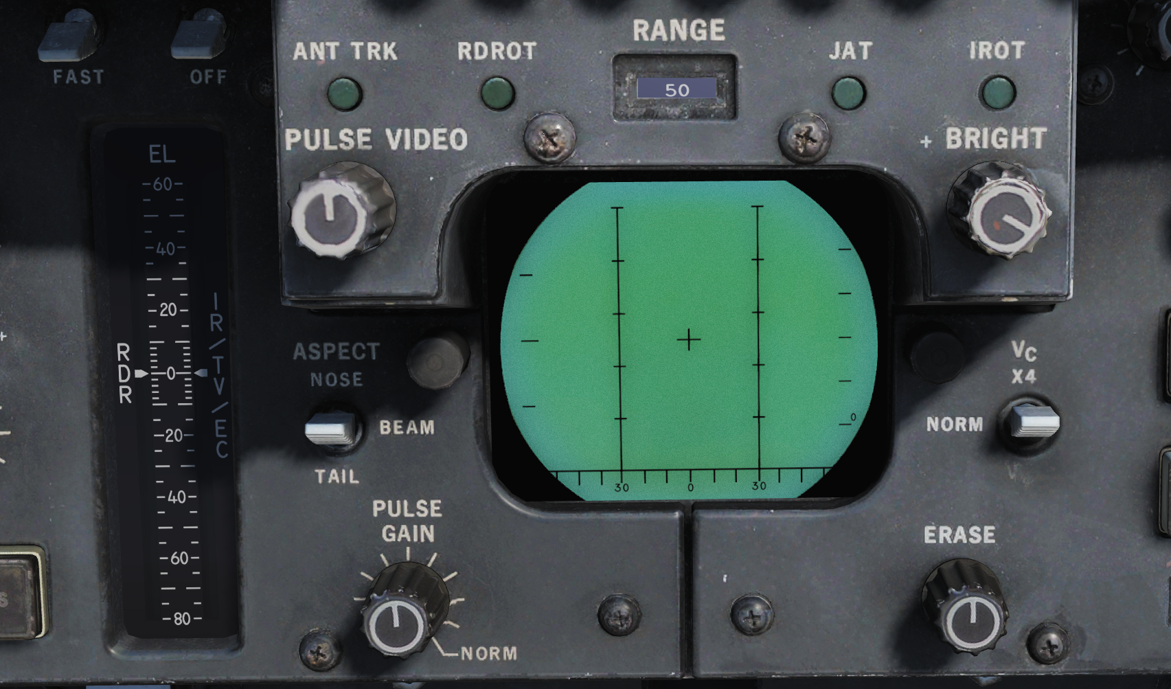
The DDD contains two indicators pertaining to the TCS.
The DDD EL meter shows current elevation of the TCS sensor LOS as long as the IR/TV mode is selected on the HCU.
The IROT light indicates the presence of a TCS track. The IROT acronym is inherited from the IRST which the TCS replaced.
HCU/TID
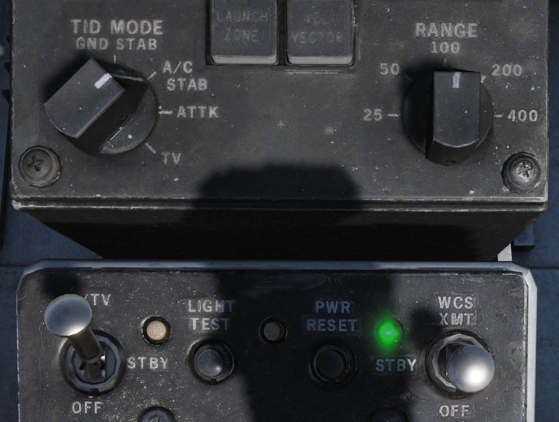
The HCU contains the power switch and indicator for the TCS as well as a button enabling selection for using the HCU to control the TCS while the TID itself has a control knob enabling display of the TCS video on the TID as well as a brightness and contrast control for the video on the TID.
The IR/TV power switch is located on the top left corner on the HCU panel and controls power to the TCS. OFF disables all power to the TCS. STBY enables power to the cooling fans and heaters in the TCS. IR/TV supplies power to all systems in the TCS, allow 1-2 minutes for the TCS to spin up and deliver video. TCS symbology on the TID on the other hand will be available directly. There is also no need to select the STBY position first, setting the switch to IR/TV directly works fine.
The indication light next to the power switch indicates a TCS over temperature condition is lit. If present the TCS should be powered off to prevent damage to the system.
The IR/TV button next to the HCU stick enables HCU stick control of the TCS sensor, half-action to manually control sensor LOS and full-action to command target acquisition.
On the TID display control the TID MODE switch set to TV enables display of the TCS video on the TID. Note that this disables the TID repeat on the HSD.
Finally, the CONTRAST and BRIGHTNESS knobs on the upper part of the TID can be used to control the TCS video shown on the TID.
Symbology
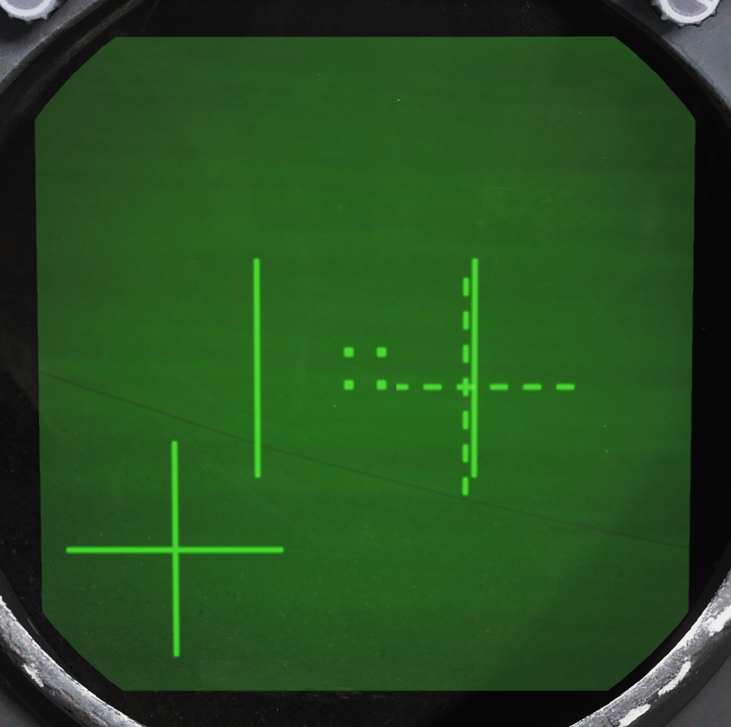
On the TID in non TV mode, a TCS track is indicated by a 1.5” strobe at TCS LOS azimuth with a hollow circle at the end.
The symbology on the video feed from the TCS has indicators for the FOV and two crosshairs indicating TCS LOS relative own aircraft, GACH, and AN/AWG-9 radar LOS relative TCS LOS, RACH. Additionally, the track window is indicated by 4 small squares representing each corner of that window.
The field of view lines are shown when in the wide FOV indicating the size of the area visible when switching to the narrow FOV. They consist of two parallel lines together creating the sides of an imaginary box indicating the narrow FOV size.
The gimbal angle crosshairs or GACH, which is a solid cross, indicate deflection of the TCS LOS from the aircraft datum line, ADL. GACH crosshair in center indicates TCS LOS along ADL and deflection towards the edges indicate deflection towards the gimbal limits with the video edges being maximum deflection.
RACH or radar angle crosshairs, a dashed crosshair, indicate radar antenna LOS when inside the current TCS FOV. When the sensors are slaved to one another RACH and GACH will coincide creating a single solid crosshair.
The track window indicates the area that the TCS contrast tracker is currently locked on to if it has acquired a target. When not in an active track these squares collapse into the center of the display being 2% of the screen width when in manual mode and 5% when in an auto mode.
TCS Operation
All acquisition modes of the TCS have in common that they can be controlled using the HCU in IR/TV mode. Selection of the IR/TV button on the HCU enables this mode and also sets the DDD EL meter (right indicator) to show current TCS sensor LOS elevation. Half-action enables the HCU to directly control the LOS of the TCS and full-action commands target acquisition using the selected acquisition mode.
For manual, MAN, TCS acquisition mode this means that the HCU must be used in half-action to position the tracking window indication over the target and then selecting full-action. If successfully acquired the track window will then expand to encompass the target and tracking will begin.
In automatic, AUTO acquisition mode half-action works the same but when selecting full-action for acquisition the TCS will instead automatically try to lock on to the target closest to the center in the current FOV. Automatic search, AUTO SRCH mode further enhances this by enabling a search pattern around the commanded FOV (by moving the sensor LOS) acquiring the first found target.
When using the TCS slave to radar option the two auto modes will automatically try to lock on to the STT target as soon as it exists and the TCS has been slewed to that target, enabling a fully automatic track of a target locked in STT. Additionally, as soon as a track is acquired from an STT lock the TCS will compare its own LOS to the radar LOS to check if the correct target has been locked, if the two LOS differ by more than a couple of degrees during a 3-second window a new acquisition will be attempted. The manual mode will also slave to radar LOS but will not lock on, instead just following the radar LOS.
To unlock a tracked target when not being slaved to radar, select half-action and release.
For information about RDR slaved to TCS check relevant header under AN/AWG-9 in this chapter.
Weapon Systems

The F-4E features two systems to assist the Pilot and WSO in air-to-ground Operations. The AN/AJB-7 ARBCS (Automated Release Control System) serves as the automated release control system for time or pitch-relative bombing. It interfaces with the Multiple Weapon Controls, Pedestal Panel weapon settings, and various munitions such as bombs, laser-guided bombs, or the AGM-45.
The Weapon Release Computer Set (WRCS AN/ASQ-91) supports various delivery modes for both level and dive maneuvers. The weapon release signal is automatically generated by the computing system, incorporating inputs such as INS velocities, radar target range, and manual inputs from cockpit controls.
The AWRU (Automatic Weapon Release Unit) receives operational power when BOMBS or RKTS & DISP is selected on the weapon selector. The control panel features two INTRVL controls and a quantity (QTY) selector.
Multiple Weapons System
The Multiple Weapons System is designed to provide a single point of management for all stores deliverable by the F-4 with regards to arming, pylon activation, delivery mode, and selective jettison. While specific weapons may have additional controls elsewhere in the cockpit on a case by case basis, all of the noted functions are driven by this panel on the left forward console in the front cockpit.
Nose/Tail ARM Switch

Beginning from the top of the panel, the four way Nose/Tail ARM switch selects the solenoids for arming wire capture on MERs and TERs, which then arm the fuzes at the point of release. Additionally, the switch position can also dictate in-flight high/low drag release mode for retarded bombs such as the Mk 82 Snakeye.
| Name | Description |
|---|---|
| SAFE | No arming solenoids activate; bombs release without fuzing enabled. |
| NOSE | Forward and center position solenoids activate to hold arming lanyards. |
| TAIL | Aft position solenoids activate to hold arming lanyards. |
| NOSE/TAIL | Forward, center, and aft position solenoids all activate to hold arming lanyards. |
For example, MK-82 Air or Snakeye variants will only detonate if the nose fuze is selected and switch between high drag configuration with the tail fuze set and low drag if not set.
MER-10 and TER-9 racks include an automatic stepper mode function to automatically bypass stations that have already released munitions. To set this function, when the BOMBS mode of the Weapon Select Knob is chosen, the Nose/Tail switch must be in the NOSE or the NOSE & TAIL position for release signals to be delivered through installed MERs and TERs and bypass empty positions; if the system is set in TAIL, an additional release pulse(s) must be applied using the bomb switch to cycle through the empty stations. Usage of the MER-10A and TER-9A circumvent this requirement.
RKTS and DISP bypass empty stations automatically.
Station Select Buttons
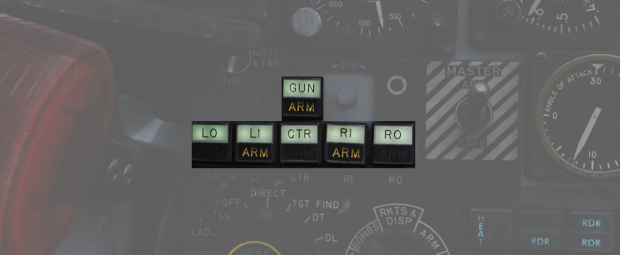
With the station select buttons it is possible to select the different armaments on the respective stations. This does not constitute air-to-air weaponry.
Mode Selection - Delivery Mode Knob
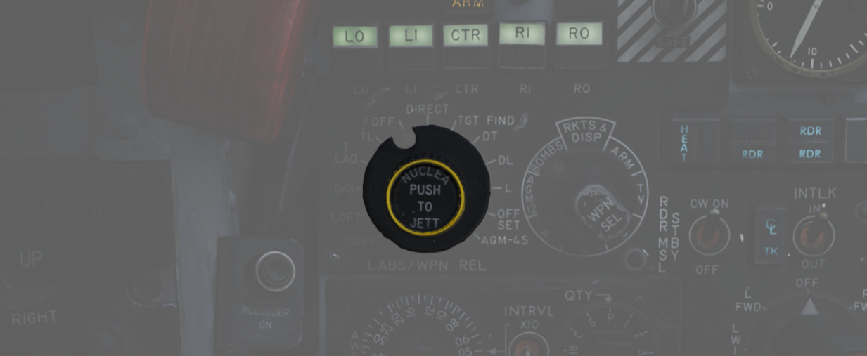
Release mode is set using the Delivery Mode Knob. Values to the left of OFF employ the AN/AJB-7 Attitude Reference and Bombing Computer Set (ARBCS), whereas values to the right of DIRECT employ the Weapon Release Computer Set (WRCS). DIRECT is the manual release mode. TGT FIND functions as a navigational mode, and cannot provide a weapon release signal to the fire control, thus can be considered in practice a "safe" position.
The values, clockwise from the left, are as follows:
| Name | Description | System |
|---|---|---|
| INST O/S | Instantaneous Over the Shoulder | ARBCS |
| LOFT | Loft | ARBCS |
| O/S | (Timed) Over the Shoulder | ARBCS |
| T LAD | Timed LADD (Low Angle Drogue Delivery) | ARBCS |
| TL | Timed Level | ARBCS |
| OFF | Off | |
| DIRECT | Manual | |
| TGT FIND | Target Find (Navigation and Pave Spike only) | WRCS |
| DT | Dive Toss | WRCS |
| DL | Dive Laydown | WRCS |
| L | Laydown | WRCS |
| OFFSET | Offset Bomb | WRCS |
| AGM-45 | AGM-45 Delivery | WRCS |
Weapon Selector Knob
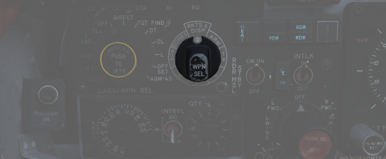
The Weapon Selector Knob is used to designate the type of weapon to be used
| Name | Description |
|---|---|
| RKTS & DISP | Rockets and dispensers. Arms AWRU release circuitry. |
| ARM | AGM-45 Shrike |
| TV | AGM-65 Maverick and other EO guided weapons. |
| C | Open/unused. May be utilized as an OFF selection. |
| B | Same function as AIR-TO-AIR button in rear cockpit. |
| A | Munitions with internally-set intervalometers (CBUs or spray containers). |
| AGM 12 | AGM-12 Bullpup. |
| BOMBS | Bombs. Arms AWRU release circuitry. |
Centerline Tank Aboard Light

The forward AIM-7 missiles can be inhibited from launch under certain centerline conditions due to possible separation issues or chance of igniting the contents of the centerline position. The CL tank light will illuminate if such a possible condition exists. The conditions that can cause this are as follows:
-
Fuel Tank or MER; the forward Sparrows cannot be launched. The CL tank light will shut off if the tank or MER is jettisoned, allowing launch or jettison.
-
BRU-5/A with single bomb; the CL tank light will illuminate. Forward position Sparrows can be launched or jettisoned; however, attention should be paid to eliminate lateral roll movements until the launched weapon is clear.
-
Aero-27/A with Centerline Arming Unit. The CL tank light will illuminate; however, the forward position AIM-7s cannot be jettisoned or released until this is removed post-flight.
Interlock Switch
The fire control system provides an inhibitor option for AIM-7 launches to confirm valid parameters are met, and is accessed with the INTLK switch. With IN selected, the missile will not release upon trigger down should any of the following not be the case:
- The IN RANGE lamp illuminated
- The target aim dot within the ASE (Allowable Steering Error) circle
- The radar knob is not in VI mode
With the INTLK switch in OUT, the AIM-7 can be launched at any time, no matter the condition of the current parameters against the target.
The INTLK switch provides no function for AIM-9 launch.
Aircraft Weapons Release Unit (AWRU)
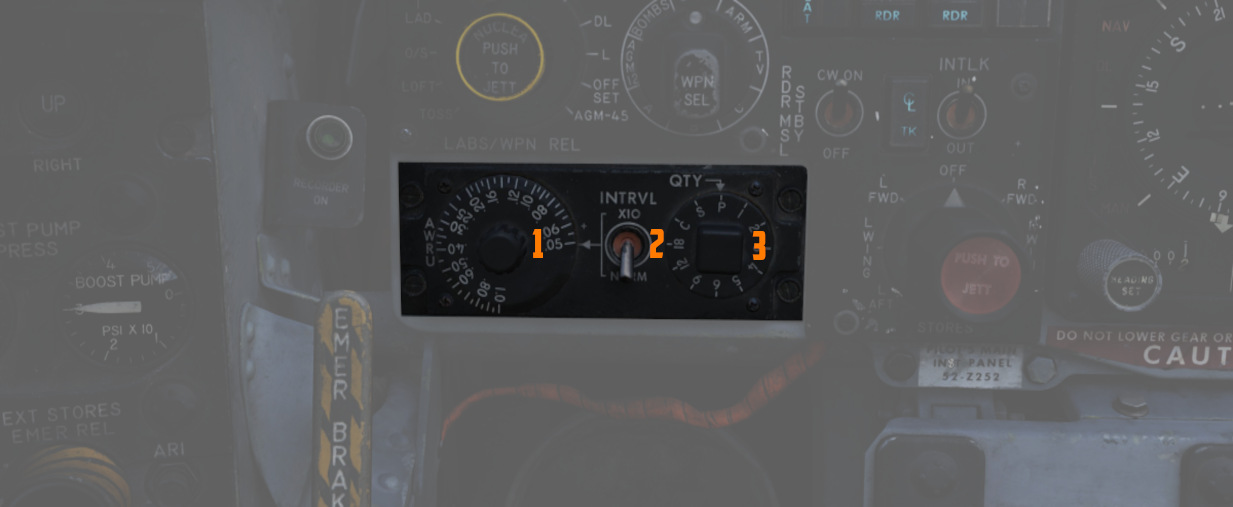
Used in the BOMBS and RKTS & DISP weapon modes, the AWRU provides interval and quantity controls for munition delivery. The AWRU has both a manual and automatic mode, and the resulting function is accessed with the appropriate settings.
The Interval Knob contains 14 values, providing base interval timing of release pulses while the bomb release button is held from 1/20th of a second (.05) to 1 second. This value can have a 10x multiplier applied to it using the INTRVL Switch. In the NORM mode of the INTRVL switch, the release will apply as on the Interval Knob, whereas when selected to x10, the 10x multiplier will apply - for example, 1 second in NORM would become an interval of 10 seconds in x10 mode.
The Quantity Knob sets the total number of munitions dropped during a bomb release hold, and applies the manual or automatic release functions based on the value selected.
Single-Manual: 1
In the 1 position, the AWRU is placed into manual mode. One munition will be dropped on each bomb release press, with releases across multiple selected stations dropping in a left-right-left pattern. The bomb release button must be released, then pressed a subsequent time, to release another round.
Single-Ripple: 2-18
In numerical positions 2-18, up to the total number of selected munitions will be dropped according to the Interval setting. As an example, with a QTY of 6 and an interval of .20, six bombs will be dropped, one every 2/10ths of a second from the press of the bomb release button. The sequence will reset upon button release, allowing subsequent ripples of the same quantity to be dropped.
Single-Continuous: C
In position C, the quantity of weapons is dictated by how long the bomb release button is held. The ripple will apply the set interval, releasing one munition each pulse, until the bomb button is released.
Pairs-Manual: P
Position P places the AWRU into pairs mode. With multiple stations selected, each time the bomb button is pressed, a weapon will be released from each station.
Salvo: S
In the S position, the AWRU enters into salvo mode, functioning like Pairs-Manual with single rounds released from each station, but using the set interval value to release multiple salvos until the bomb button is released.
Weapon Release Computer Set (WRCS)
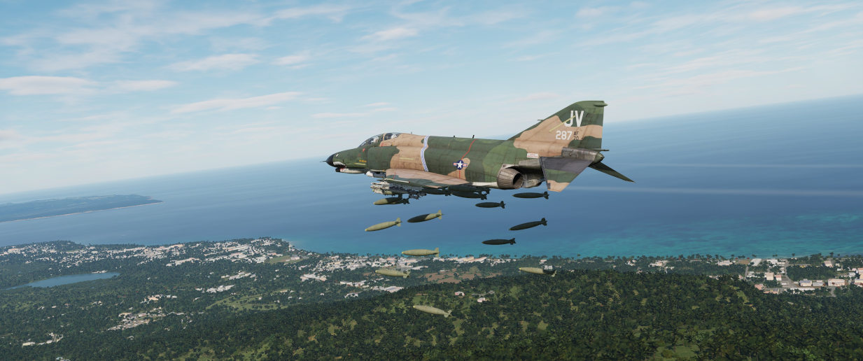
Provision for the F-4E to perform accurate level and dive munition delivery is provided by the AN/ASQ-91 WRCS. The WRCS inputs are set with the associated panels in the cockpits, and these commands, along with INS data and radar target ranging, are used by the ballistic computer to provide the release signal.
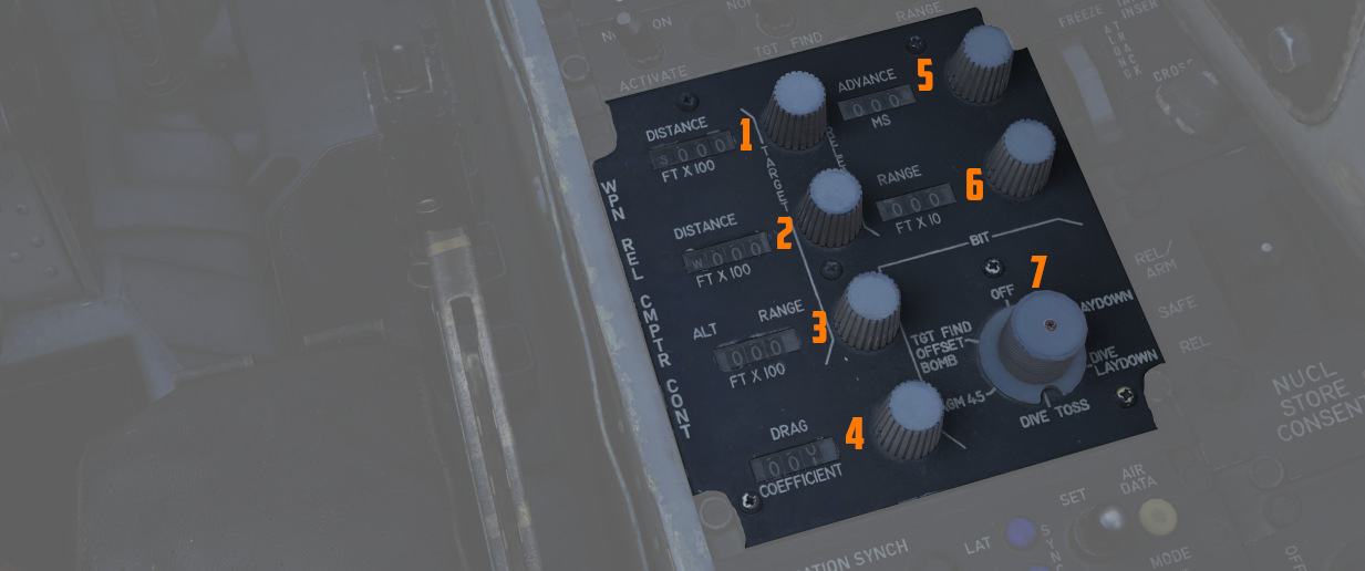
Target Range Controls
The Computer Control Panel found in the rear cockpit has three TARGET entry controls, two RELEASE entries, and a bomb DRAG COEFFICIENT entry setting, as well as a BIT control knob for system function check. Target entry is relative to the predetermined IP.
The upper range control input is for North/South, and selection of relative bearing is noted by the N or S prefix at the start.
The middle range control input is for East/West, and like the previous, the E or W prefix on the range sets the relative bearing direction.
The final ALT RANGE entry is for target altitude- whether the target or RIP (Radar Identification Point) elevation as MSL, or the target/RIP's pressure altitude. In Laydown mode the entry refers to the distance between the IP and the target in hundreds of feet.
Entries for North/South and East/West are in 100 foot increments, and a maximum value of up to 99,900 feet may be entered for these distances. The ALT RANGE entry has a maximum of 24,900 in 100 foot increments.
💡 The WRCS can be damaged if the ALT RANGE entry is greater than the aircraft's current MSL (x100) in TGT FIND and OFFSET BOMB modes.
Release Range Control
The Release Range control is used to manually set bomb range in tens of feet, and is accessible in the Laydown, Dive Laydown, and Offset Bombing modes. The maximum setting is 9990 feet (999x10), and when used in a WRCS/AJB-7 integrated delivery, the actual range can be as high as 99,900'.
The Rg control should not be set to the same value as the target range control. Otherwise, the bomb rack delay may release late, or not at all.
Release Advance Control
Operative in all WRCS and WRCS/LABS integrated motes, the Release Advance Control works in conjunction with the AWRU to advance the release signal in milliseconds. Whereas the AWRU Intervalometer setting triggers the release pulse sequence from the moment the bomb release button is pressed, when the Release Advance Control is applied in a WRCS driven delivery, the specific bomb location in a multiple ripple sequence can be calculated in advance, allowing the most effective spread possible across a given target.
As an example, an AWRU single-ripple quantity release of 4 is selected with an interval of 120 milliseconds. To place the third bomb in the ripple on target, the following equation is used:
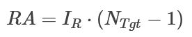
where
RA= Release Advance Setting, millisecondsI_R= AWRU Release Intervalometer setting, millisecondsN_Tgt= Impact Sequence number of bomb desired on target
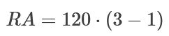
Thus, for this release, we would set the value of RA to 240 msec. This would produce a spread of two bombs ahead of target, one on the calculated target point, and one behind.
The maximum setting for the Release Advance Control is 999 milliseconds. A calculator to calculate the Release advance in-game is provided with the bombing calculator. You can open and close it by pressing RCTRL+B in game.
Drag Coefficient Control
Used only in the Dive Toss Mode, this entry is a bias factor prepared for the ballistic computer to compensate for actual bomb trajectory. The maximum setting for this value is 9.99.
Ballistic Computer
The ballistic computer is not directly accessed by the flight crew, but instead pre-set based on the configured loadout by the ground crew to add the necessary ejection bias factors. The computer uses these pre-set bias factors in conjunction with a coefficient setting for munition drag in the Dive Toss mode to calculate accurate delivery.
WRCS Built-In-Test (BIT)
The BIT control is used to confirm go/no-go status of the WRCS. The BIT system checks individual bomb modes individually, and effectivity of the given setting is confirmed by selecting the desired mode, pushing the center of the knob PUSH FOR BIT for five seconds, then pressing the FREEZE button in conjunction with the PUSH FOR BIT button. Confirmation of mode performance will be displayed as GO or NO-GO. Should a mode be checked a subsequent time during a flight and a NO-GO response is received, it can be disregarded.
Cursor Control Panel
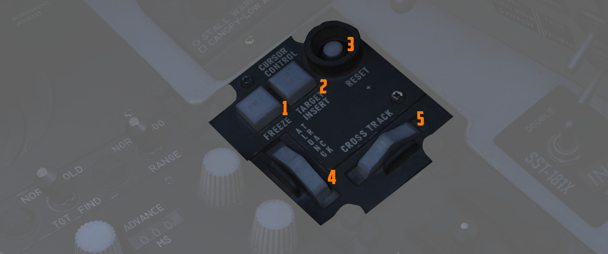
The Cursor Control Panel provides the controls needed for TARGET FIND and OFFSET bombing modes. The panel has two wheels named ALONG TRACK and CROSS TRACK, which is used in the MAP-PPI mode to position their respective cursors over the Radar Identification Point (from this point denoted as RIP). The ALONG TRACK control, which presents relative range to the RIP, also includes an internal switch enabling the cursor instructions to be acknowledged by the WRCS ballistic computer, and must therefore be the first applied command in the target insertion sequence.
Once the ALONG TRACK (range hemisphere) and CROSS TRACK (vertical line) cursors are aligned over the RIP, the FREEZE button is pressed to initiate WRCS ground path tracking of the specified point. The button remains illuminated until the RESET button is pressed or another bombing mode is selected.
With WRCS ground tracking initiated, the TARGET INSERT button is pressed for the ALONG TRACK and CROSS TRACK cursors to shift from the RIP to the offset target. Once selected, target steering information is provided from the WRCS to the BDHI, ADI, HSI, and optical sight. In the AGM-45 missile mode, the AoA Indexers will provide maneuver commands for level, dive, or climb requirements to align for seeker acquisition. Further, unless the Pull up tone switch is disabled on the LABS panel, an audio tone will be triggered from the point of bomb release button press until the first bomb releases from the aircraft; this function is nominally for training purposes, as it can preclude other system audio volume.
Weapon Delivery Panel
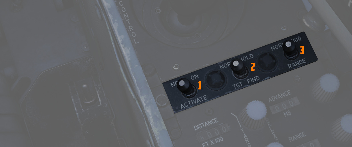
The Weapon Delivery Panel permits the aircrew to use the WRCS TGT FIND functions in LABS (ARBCS) modes - those found on the left side of the pilot's Delivery Mode Knob.
The TGT FIND switch on the panel functions the same as the TGT FIND mode on the Delivery Mode Knob. The Delivery Mode Knob overrides this switch in any mode outside of TGT FIND, and should be set back to NORM. The HOLD position energizes the target finding circuits in conjunction with any LABS or DIRECT mode the pilot selects.
The RANGE Switch is functional in any WRCS mode requiring a Release Range setting. The NORM position applies the noted x10 multiplier on the displayed Release setting, whereas selecting x100 applies a multiplier of 100 to the counter value.
The ACTIVATE Switch triggers the prerequisite activation signals to the LABS circuits once the aircraft has passed within the Release Range. The switch should only be placed in ON after target insert has been pressed and the ALONG TRACK and CROSS TRACK cursors have transitioned to the target.
Attitude Reference and Bombing Computer Set (ARBCS)
The AN/AJB-7 ARBCS is the automated release control system for time or pitch-relative bombing. Interfacing with the Multiple Weapon Controls, Pedestal Panel weapon settings, and bomb, laser guided, or the AGM-45, the system releases the selected munition once the respective Bombing Timer or respective Bomb Release Angle Computer pitch angle (gyro) target has been achieved.
The left side of the Delivery Mode Knob selects the ARBCS release modes. Both LOFT and T LAD modes provide weapons release in a pull-up, with LOFT selecting a 4.0 G pull-up schedule and weapon release on achieving a set gyro angle value, whereas T LAD assumes a 3.5 G pull-up schedule and release at the end of the Bombing Timer setting. Necessary values for Low and High angle, as well as the Bombing Timer are found on the provided tables.
Bomb Release Angle Computer
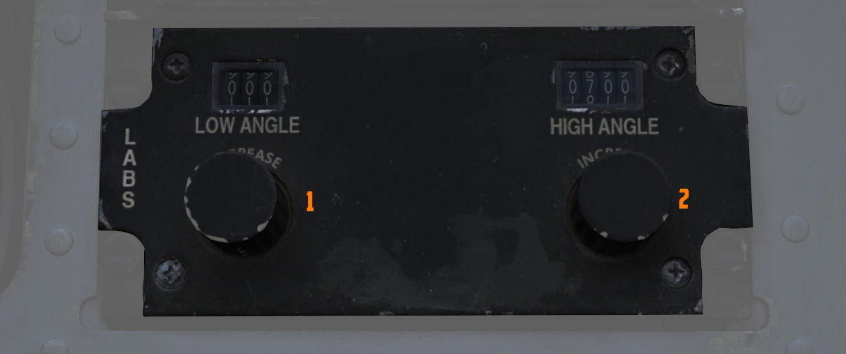
The Bomb Release Angle Computer provides entry of the necessary target pitch angles for ARBCS bombing modes. The values of HIGH (70 to 179.9 degrees) and LOW (0 to 89.9 degrees) are controlled using their respective entry knobs. Internally, the computer contains the release switches, as well as the resolver to transmit the target angle values to the ADI director pointers.
A calculator for the input values in-game is provided by the bombing calculator. You can open and close it by pressing RCTRL+B in game.
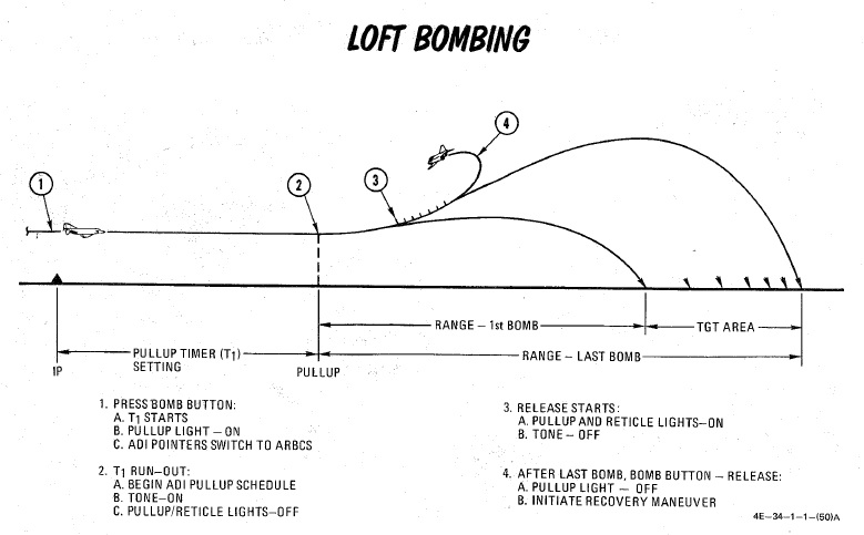
Bombing Timers
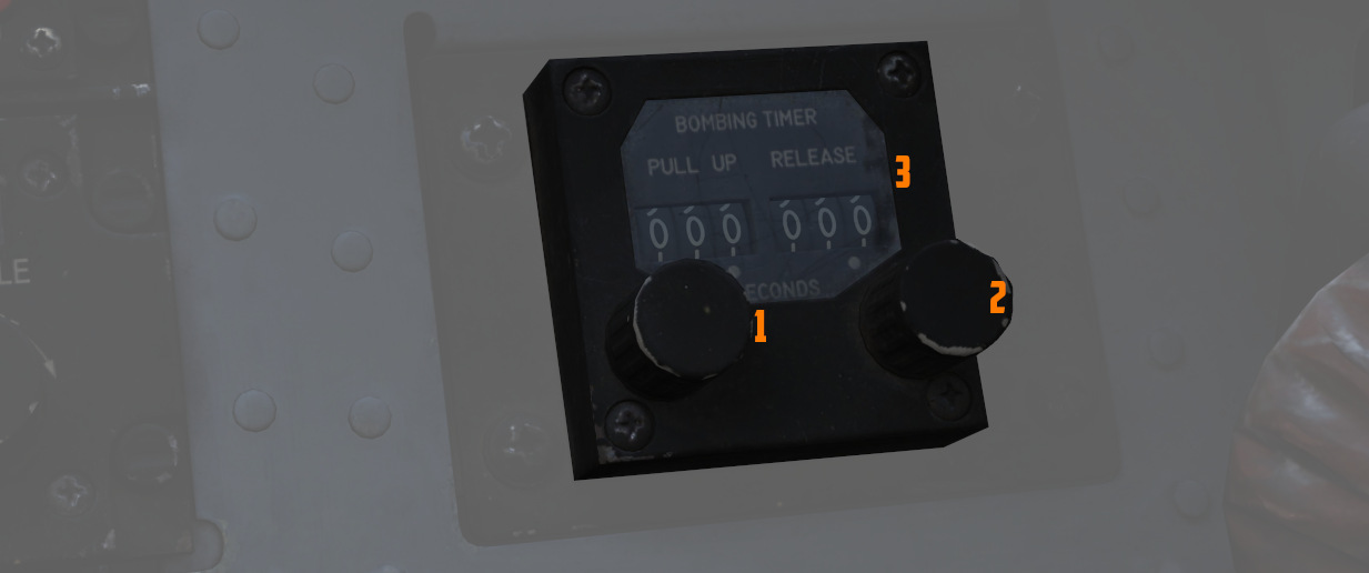
Timers for ARBCS bombing modes are available for PULL-UP (0 to 60 seconds) and RELEASE (0 to 30 seconds). Both can be set in increments of 0.1 second, with 0.1 second as the minimum setting. The reference windows do not count down during the bomb run.
When the PULL-UP timer is complete, required PULL-UP signaling will initiate, along with any ADI director programming to show proper flight path. RELEASE timing is mode dependent, and will occur once PULL-UP is complete, if required.
In LOFT and O/S modes, only PULL-UP timing is activated, and a value must be set to energize the ADI pull-up flight path program.
In T LAD and TL, PULL-UP and RELEASE are both activated, in sequence, and both require a value entry- PULL-UP to energize the flight path programming, and RELEASE to generate the munition release signal.
In integrated LABS (ARBCS)/WRCS bombing, the above requirements are the same; however, the WRCS initiates the bomb run timing, rather than pressing the bomb button. When the WRCS initiates timing, an audio tone is applied to signal timer start.
A calculator for the input values in-game is provided by the bombing calculator. You can open and close it by pressing RCTRL+B in game.
ARBCS Indicators
During ARBCS weapons delivery, a number of indicators are available to confirm run initiation and at what step of the given run the aircraft is in:
- Upon run initiation (bomb button press/WRCS initiation) and PULL-UP timer
start, the Pull-up light turns ON.

- At PULL-UP timer completion, the Pull-up light turns OFF, the reticle light turns OFF, and a steady Pull-up Tone (if switched ON) occurs.
- As release pitch angle is attained, the Pull-up light turns ON, the reticle light turns ON, and the Pull-up Tone stops.
- When the bomb button is released, Pull-up light turns OFF.
This indication sequence can occur with the master arm in SAFE for training purposes.
Gyro Fast Erect
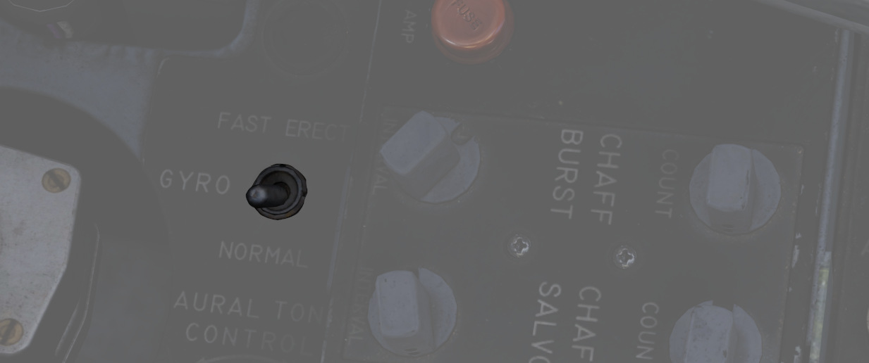
Due to rapid maneuvering during a bombing run, gyro deviation can occur due to fluid migration. While this deviation will resolve naturally at a rate of 1 to 2 degrees correction per minute over time, it can quickly be corrected by using the FAST ERECT switch found in the front pilot cockpit on the left side console, at a rate of 15 degrees per minute. This switch should not be held for more than 60 seconds, or damage can occur to the gyro.
Lead computing optical sight system (LCOSS)

The lead computing optical sight system or short LCOSS, is used to establish a visual sight reference to either air-to-air or air-to-ground weapons delivery. A red reticle is projected on a combining glass. The LCOSS features seven different modes that can be selected via the Sight Mode Knob.
LCOSS Controls
Sight mode knob
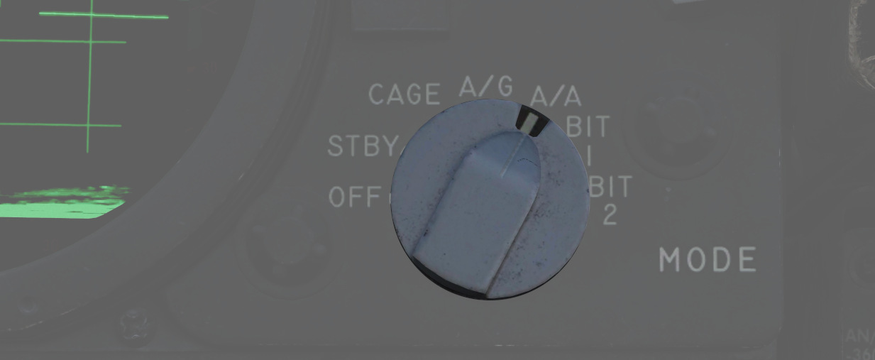
The sight mode knob selects the mode of operations which are the following:
| Sight mode knob | Function |
|---|---|
| OFF | De-energizes the sight system. |
| STBY | Energizes the sight system for warmup but does not display any reticle. |
| CAGE | Reticle is displayed and caged at the radar boresight line (RBL). |
| A/G | Selects the air-to-ground mode. The reticle is depressable from zero mils to 245 mils below the fuselage reference line (FRL). |
| A/A | Selects the air-to-air lead compute mode. The reticle position is governed by the sight gyro, radar range, the CADC Sensor and the cage button on the throttle. |
| BIT 1 and BIT 2 | Energizes the lead computing amplifier relays so that fixed voltages are applied to the sight system for a self test. Displays self test pictures. |
Reticle depression control
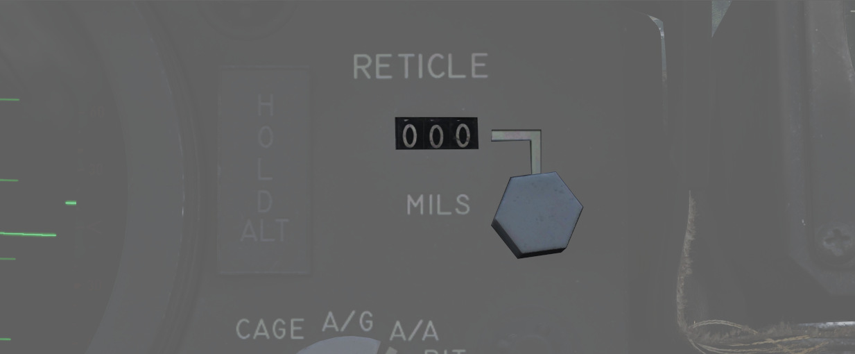
The reticle can be depressed by rotating the reticle depression knob until the readout (in one-mil increments) shows the desired sight setting. The Reticle cannot be positioned manually in azimuth.
Reticle intensity control
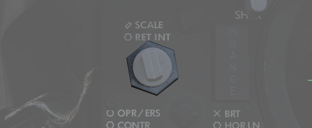
Rotating the reticle intensity control knob changes the brightness of the reticle.
Shutter lever control
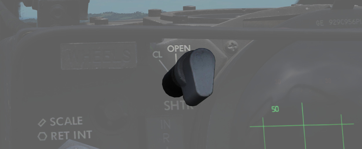
The shutter control lever is a two position lever with positions of CL (closed) and OPEN. In the CL position a shutter is placed between the optical light source and the combining glass thus preventing damage to the optics from bright sunlight. In the OPEN position the shutter is removed and the reticle will be displayed.
Reticle Image
The reticle image that is projected onto the combining glass is composed of a fixed reticle, roll reference tabs, and a range bar. The fixed reticle consists of 2-mil diameter pipper located in the center of a 25-mil diameter segmented circle, and a 50-mil diameter completed circle.
The roll reference tabs rotate about the 50-mil circle. The roll reference tabs have two seperate functions. During the offset bombing mode and the target finding mode the roll tabs provide steering information from the WRCS. The position of the roll tabs, with respect to the fixed index tabs, indicates the angle between the ground track and course to the target. In every other mode of operation the roll tabs indicate the aircraft roll attitude, supplied by the INS.
| Roll tab left roll | Roll tab right roll |
|---|---|
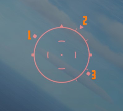 | 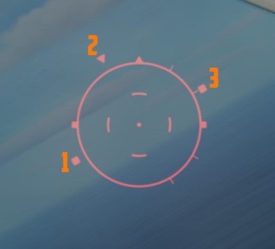 |
| 1 left roll tab, 2 center roll tab, 3 right roll tab | 1 left roll tab, 2 center roll tab, 3 right roll tab |
The range bar is semicircular and appears on the inside of the 50-mil circle only when a target has been acquired by radar lockon. The instantaneous length of the range bar, and the rate at which the length is changing indicates the actual radar slant range and the range between the aircraft and the target. The minimum length of the range bar (and minimum range indication) exists at the 6 o'clock position. With gun selected the inside tab of the range bar at 6 o'clock, the actual radar range is 1000 ft. At the 5 o'clock position the range bar is 2000ft continuing with 1000ft increments per tab. The maximum range that can be shown is 6667ft with guns selected. When any other mode than GUN is selected the range bar is 3000ft at the 6 o'clock position and 6000ft at the 5 o'clock position, with increments of 3000ft per tab. The maximum displayable range is then 20000ft.
| Range bar with guns | Range bar in any other mode |
|---|---|
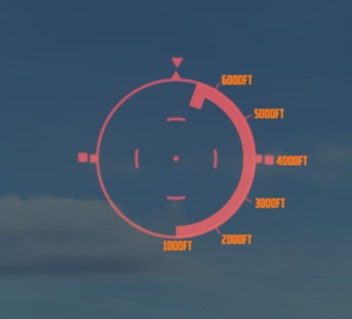 | 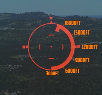 |
Reticle Cage Function
The reticle cage function is applied through the CAGE button on the throttle. With the sight operating in the (GUNS) A/A mode and with CAGE pressed (no radar lockon) the reticle is caged at radar boresight line (RBL). When CAGE is released, a pseudo range of 1000ft is supplied to the computer but the range bar is not displayed. With radar lockon the stiffening function is applied as long as CAGE is pressed. The range bar continues to indicate the actual radar range or the maximum displayable range. When CAGE is released the reticle moves in azimuth elevation to display the lead required to a maximum of 4000ft. This will only happen with GUNS selected.
LANTIRN
 U.S. Navy photo by Photographer’s Mate 2nd Class Felix Garza Jr. (030325-N-4142G-009)
Description
The LANTIRN or Low Altitude Navigation and Targeting Infrared for Night began life as combined targeting and navigation pods designed for the F-15E and F-16. When the US Navy became interested in using the F-14 Tomcat in the A/G role Martin Marietta (now Lockheed Martin) began its own program to show that the LANTIRN could quickly be adapted for F-14 use.
As the pod was adapted for the F-14 the secondary navigational pod was deleted, keeping only the targeting pod. The pod was wired up to its own control panel as the F-14 didn’t have the required 1553-bus for complete integration. The control panel was patched into the TCS -> TID video feed allowing it to select either the TCS or the LANTIRN for display on the TID and VDI.
While the pod can read waypoints and selected weapon from the WCS, the pod has its own GPS receiver and is otherwise self-contained and controlled only via its own control panel. Additionally, it also has its own weapons release guidance removing the need to boresight the pod to the aircraft, a time-consuming task.
The FLIR sensor itself has three different zoom levels or fields of view (FoV). The Wide FoV limits are 5.9° and allows a maximum slew rate of 8.5°/s. The Narrow FoV limits are 1.7° and allows a maximum slew rate of 1.8°/s. The last mode, the Expanded FoV is a digital zoom of the Narrow FoV, meaning that the resolution will be worse in this mode. The FoV limits for the Expanded FoV are 0.8° with a max slew rate of 0.7°/s.
Controls and Displays
All the controls for the LANTIRN are situated on its own control panel mounted on the RIO’s left side console when the pod is present, including the switch controlling what video feed the TID and VDI display in the TV mode.
LANTIRN Video Elements
The FLIR (Forward Looking InfraRed) video-feed from the LANTIRN has superimposed data readout for the crew’s use. This video-feed can be viewed both on the TID (in TV-mode) and on the VDI (also in TV-mode) when the FLIR feed is selected on the control panel.
Amongst other things the displays show own aircraft position, target position as well as targeting cues to the crew. When using the LANTIRN for A/G attack these readouts are also used as targeting and release cues.

-
Own aircraft data is shown in the upper left corner, showing position, altitude, groundspeed and pitch angle (dive).
-
The pod displays whether it’s using white hot or black hot (WHOT and BHOT) as well as if the AGC (Automatic Gain Control) or MGC (Manual Gain Control) is in use.
-
The lower left datablock shows pod information, SR is slant range (line of sight range), AZ and EL is pod line of sight azimuth and elevation relative aircraft ADL (with AZ having L or R for left or right of aircraft heading). Below that is current UTC time and then IBIT codes below that.
Note: IBIT codes are not implemented currently and the clock will show local time.
-
The lower middle shows current pod mode (A/A or A/G) and track mode (AREA, POINT or Q designations) on the left side. The right side shows currently selected weapon and laser code while above and in the center an L is shown when the laser is armed and flashing when firing the laser.
-
The lower right shows data for currently selected Q (slewpoint) except for QSNO, QADL and QHUD, TTG being time to go until on top of currently selected Q, the rows below that, bearing and range to Q, ELEV indicating elevation in feet of Q and lastly, below that, Q location.
-
The crosshairs showing tracked position, in this case we have a bounding box, indicating currently tracked target in point mode. The two widest zoom modes will have boxes showing the field of view for the next, narrower, mode. Additionally there’s a small white square (FLIR pointing cue) moving around showing the current pod line of sight relative to aircraft from a top-down perspective. In this case it’s right next to the upside-down ^, top center, indicating that the pod is looking ahead of the aircraft. If the square is centered the pod is looking straight down and below center it indicates the pod looking aft.
-
The steering guidance towards the selected Q, the top one being commanded heading and the vertical one on the right the bomb release cue.
- The commanded heading shows current aircraft heading above the inverted ^, with the commanded heading being displayed as a relative bearing either L (Left) or R (Right) of current aircraft heading below the line. The commanded heading is also indicated by a vertical line bisecting the horizontal one.
- The right, bomb release cue, is only shown if the selected Q is QDES and shows a vertical line along which a release cue travels downwards. This release cue is only visible with a valid weapon selection (bomb) and when it reaches the two tick marks, that’s the cue to release. Below the line is the indicated TREL (Time to Release) in seconds, changing to TIMP (Time to Impact) after release.
Around this all is the masking curve, indicating at what angles the pod will be masked by own aircraft (looking into the aircraft hull). This is relative to the FLIR pointing cue, when the cue moves outside the masking curve the sensor will be blocked by the hull.
Control Panel
The control panel contains all the controls for the pod, including the control stick.

-
The power switch for the LANTIRN pod is located top left with OFF disabling power to the system, IMU (blocked in above image) powering only the LANTIRN IMU and POD powering the whole system.
- Note: IMU selection has no current DCS function.
-
The MODE switch switches the POD sensor between STBY (Standby) and OPER (Operational).
-
The LASER ARMED light illuminates when the laser is armed while the LASER switch arms it. (ARM and SAFE positions available.)
-
Down right is the VIDEO switch which controls what video is fed to the TID and VDI, FLIR selecting LANTIRN FLIR video and TCS selecting TCS video.
-
The four grouped indicator lights indicate various error states in the LANTIRN system and the IBIT button initiates the IBIT (Initialized Built-In-Test).
Note: The IBIT and fault indicators are not currently implemented in DCS.
Control Stick
The control stick for the LANTIRN operates the LANTIRN’s sensor itself, note though that the stick itself does not move, the buttons and hats on the stick are used to control the pod.

-
The left four-way hat, S3, allows selection of QWp- and QWp+ (left/right) in addition to Point Track (up) and Area Track (down) modes.
-
The center slew hat is used to slew the sensor line of sight itself and depression of this hat switches between white hot (WHOT) and black hot (BHOT) sensor modes.
-
The right four-way hat, S4, allows for selection of QADL/QHUD (up), QDES (right) and QSNO (down) in addition to declutter level which is cycled by momentary depression of the hat. The left slider additionally changes the right hat function as detailed further down.
-
The red button on top is used to cycle between the three fields of view (zoom levels) of the IR sensor.
-
The two-way hat on the side selects either the A/G or A/A modes of operation for the pod.
-
Located on the left side of the stick head is a two-way slider, spring-loaded to return to center. This switch changes the function of the right four-way hat.
- Sliding it forwards allows for selection of manual gain while releasing and sliding it forwards again reselects automatic gain. Change of the manual gain with manual gain already selected can be done by sliding the switch forwards and holding it for 2 seconds. With this mode active up/down on the right hat increases and decreases the gain while left/right decreases and increases level.
- Sliding the switch aft momentarily allows selection of used laser code, while sliding it aft and holding allows for focus control. When set to laser code change, the right four-way hat selects digit to change with left/right and increases and decreases the selected digit with up/down. In focus control up/down increases and decreases focus.
-
Located on the front of the stick is a two-stage trigger, first detent manually lasing while the second detent fires the laser and designates QDES at current sensor position.
-
Lastly on the front side of the stick is the latched laser fire button. Selecting it fires the laser for 60 seconds which can be overridden by pressing and releasing the first trigger detent. A renewed press on the laser latch button resets the latched laser fire timer to 60 seconds, beginning a new 60-second countdown.
Operation
Startup
To start the LANTIRN from cold, set the power switch to POD. This will start the LANTIRN power-up sequence which takes 8 minutes. When ready, this will be indicated by the MODE switch showing STBY.
When at STBY, depression of the MODE button switches the system to OPER (Operational), enabling the LANTIRN sensor after a 30-second initialization.
Lastly, to allow display of LANTIRN FLIR video, select FLIR on the VIDEO switch.
Sensor Modes and Operation
The LANTIRN has two “master” modes, A/A and A/G. Both work similarly but are optimized for different types of targets. Additionally, the A/G mode allows for bomb release guidance.
The pod has two main ways of controlling the sensor line of sight, either via contrast lock (image following) or via being slaved to a Q designation.
The Area and Point Track modes are the two contrast lock modes in which the LANTIRN locks onto contrast differences in the LANTIRN FLIR video itself. This in itself only allows for angle tracking which gives imprecise ranging using own aircraft position and pod line of sight to calculate target position. It does however allow the system to track moving targets.
The last tracking mode has the sensor slewed to a stored location/direction, called a Q. The directional Qs do not allow for guidance to a location while the location Qs do.
QSNO and QADL/QHUD are directional. QSNO slaves the sensor to the ground 15 NM directly in front of the aircraft along own aircraft heading. QADL and QHUD slave the sensor to either ADL (in A/A) or the aircraft wings symbol on the HUD (in A/G).
The location Qs have two sources, QWp- and QWp+ on the stick’s left hat can be used to cycle through the WCS waypoints, allowing the RIO to slew to the different waypoints for navigation and target localization.
The other source is via pod designation. By selecting the second detent on the LANTIRN trigger the current sensor track or location is lased and a new location stored using that data. This is called the QDES and is used to designate targets for engagement as well as allowing the RIO to select a new location for navigational reference on the fly. The QDES can not however be automatically transferred to the WCS, but the RIO can enter it manually using the target location information in the pod video feed.
The lower right datablock is enabled for the location Qs only but will remain even when the pod is slewed away in area or point track modes. As soon as another Q is selected however, it will update to that location instead or be removed if a directional Q is selected.
A/G Target Engagement and Designation
The LANTIRN steering cues for ground target engagement are automatically enabled when the LANTIRN is slewed to QDES or a new QDES is designated. The QDES itself will remain even if a new Q is selected and as long as it exists, the steering cues will point towards QDES even if slewed to another point. This is important to keep in mind as it is easy to think that the steering commands are to the current sensor location instead of the QDES.
The laser designation itself can however point to a different location than the QDES as the laser always points to the current track. This can be used to quickly change back to a target marked by the QDES if desired and when lasing a moving target a QDES should be set at an estimated target location at impact (estimated manually) and then the point track mode or manual slew can be used to designate the actual target more precisely.
To change laser code, move the stick left side slider aft and release, this will change right hat (S4) into laser code mode. The currently selected digit will blink and the S4 hat can then be used to set the digits. Left/right change what digit to set and up/down change the value of the digit. Renewed selection of aft on the left slider will then exit the laser code mode.
If the right, S4, hat is depressed while in laser mode the automatic lase mode will be enabled, indicated by the M (for manual) left of the digits changing to an A (autolase). Repeat to switch back to manual mode. While activated, the autolase mode will begin firing the laser at 10 seconds TIMP until TIMP zero +4 seconds.
The bomb release cue is only visible with a valid weapon (bomb) selected and the selected bomb is read from the weapon selector wheel on the RIO armament panel via the WCS. The actual bomb release can be accomplished using the computer pilot or computer target modes but the manual mode is recommended. In manual mode the pilot follows the cues in the LANTIRN video feed on the VDI and releases the bomb when cued by the LANTIRN.
Electrics
Integrations
Modes
Laser System
Weapon Release Modes
Other
Defensive Systems
The F-4E features up to 4 AN/ALE-40 Countermeasure dispense Pods. The AN/ALE-40 Countermeasure dispense Pods are used by a variety of US Aircraft.
Also found on the F-4E is the ALR-46 Radar Warning Receiver ( subsequently RWR) is the F-4E's passive situational awareness system for detection of airborne and surface-to-air radar threats.
For extended protection and radar jamming it can also carry the ALQ-131 ECM Pod.
 An F-4E Phantom II pilot is silhouetted in the cockpit
of his aircraft as he prepares for a mission during Exercise TEAM SPIRIT'86
An F-4E Phantom II pilot is silhouetted in the cockpit
of his aircraft as he prepares for a mission during Exercise TEAM SPIRIT'86
Countermeasures
AN/ALE-39 Countermeasures Dispensing Set
Description
The AN/ALE-39 is the countermeasures dispensing set installed in the F-14 in this simulation. It controls its own set of launchers located between the engine nozzles on the underside of the so-called beaver-tail.
The launchers each have two sections, one containing 10 cartridges and the other 20. They are referred to the left and right dispensers even though the left is really the front one and the right the back one with both being mounted in line on the left side of the tailhook. This is a remnant from the earliest model F-14s carrying the AN/ALE-29.
This all sums up to a capacity of 60 cartridges in the system with each section necessarily holding one type of cartridge meaning that any combination of cartridges is possible as long as each type’s quantity is a multiple of 10. The system itself has no real knowledge of what is loaded where so incorrectly programming the system can lead to the wrong type of cartridge being ejected.
The system itself can be operated manually from the control panel in the RIO pit or the DLC thumbwheel on the pilot stick when the flaps lever is in the up position. It is also capable of running programmed sequences of ejection which in turn can be initiated manually by the RIO from the control panel or the direction hats mounted on the hand hold over the DDD. In addition, the AN/ALR-67 can also initiate the chaff ejection program if set up correctly on the AN/ALE-39 control panel.
Controls and Operation
Note: In DCS the F-14 countermeasure loadout is set in the Mission Editor, see DCS Mission Editor Functions Specific to the HB DCS F-14 or controlled through the radio menu under ground crew. The default setting in the mission editor is bypassed. To see the real loadout check the kneeboard.
Programmer

The programmer is used to set up what countermeasure cartridges are loaded where and to set up the different ejection programs. The panel is located on the right horizontal console of the RIO cockpit.
The left side of the programmer holds the controls (thumbwheels) for the different ejection programs, one section for each type of cartridge.
- CHAFF section: Controls how to eject chaff in program mode. The chaff sequences are programmed to launch a number of salvos, each consisting of a burst of a set amount of cartridges.
- B QTY: Controls how many cartridges to eject in each burst, selection of 1-4 cartridges and C for continuous and R for random (4-6 cartridges) possible.
- B INTV: Sets the time in seconds between each individual cartridge ejection in each burst, possible settings being .1 (0.125), .2 (0.25), .5 (0.5), .7 (0.75), 1 and R for random.
- S QTY: Controls how many salvos of bursts to eject in each program, settings available are 1, 2, 4, 6, 8, 10, and 15.
- S INT: Sets the time in seconds between each salvo in the program, available settings are 2, 4, 6, 8, and 10.
When using the random and continuous settings for B, special conditions apply.
-
B at C QTY and R INTV: Sets the first 3 cartridges to launch at 0.125-second intervals, the rest at random intervals from 0.25 to 4 seconds. Ejection disregards the S settings and continues until all cartridges are ejected.
-
B at R QTY and R INTV: Sets each burst to have between 4-6 cartridges and to eject at random intervals between 0.25 to 4 seconds. The first burst in a salvo will always launch the first 3 cartridges at 0.125-second intervals.
-
B at R QTY and INTV at set number: Sets each burst to launch between 4-6 cartridges at set interval. First burst will always launch first 3 cartridges at 0.125-second intervals.
-
B at fixed QTY and R INTV: Sets each burst to eject one cartridge disregarding B QTY.
-
JAMMER section: Controls the ejection of jammer cartridges in programmed mode.
- QTY: Sets how many jammer cartridges to eject, possible settings are 1-4.
- INTV: Uses all three indicated thumbwheels to set time in seconds between each ejection in the program. Settings from 1 to 299 possible in 1-second increments.
Note: Jammer cartridges not currently implemented in DCS.
- FLARE section: Controls ejection of flares when using programmed mode.
- QTY: Sets amount of flare cartridges to eject, possible settings being 2, 3, 4, 6, 8, and 10.
- INTV: Sets time interval between each ejection in seconds, possible settings being 2, 4, 6, 8, and 10.
The right side of the programmer sets the type of cartridge loaded into each section and the reset switch used after loading new cartridges.
The L10, L20, R10, and R20 thumbwheels can be set to C, J, or F setting what cartridge is loaded into which section.
Note: Incorrectly setting type of cartridge loaded can result in the launch of the wrong type of cartridge.
The RESET switch needs to be used to reset the system's internal counters after loading new cartridges into the launchers. Needs to be held to reset for at least 5 seconds to reset the system.
Control Panel
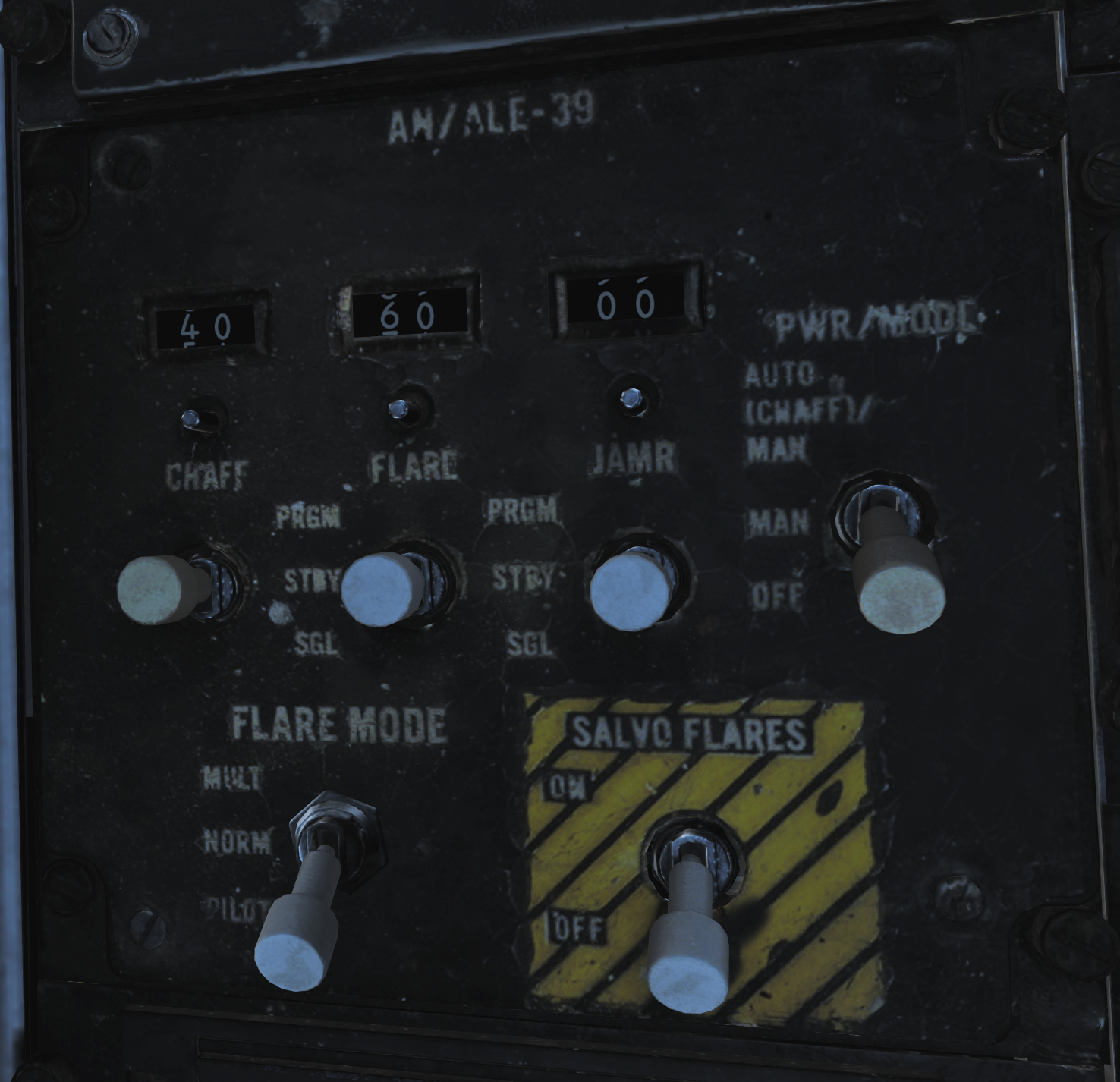
The control panel is used to control system power, to set up automatic ejections, and to manually eject cartridges and is also located on the RIO right horizontal console.
- The mechanical counters on the upper part of the panel are used to indicate remaining cartridges of each type. They need to be set up manually using the knob below each counter but decrease automatically as each cartridge ejection pulse is sent. As they’re set manually it’s possible to end up in a situation where the counter is at 0 but additional cartridges are still available. In these cases, ejection pulses will still be sent but the counter will remain at 0.
- Below each counter, each cartridge type has a switch for manual ejection commands. The switches are momentary and spring-loaded to center, each having three positions. PRGM initiates the respective set ejection program, SGL commands ejection of a single cartridge of the respective type, and STBY is the default center position not commanding manual ejection.
- The PWR/MODE switch enables power to the AN/ALE-39 and can enable automatic chaff launch via the AN/ALR-67 RWR.
- AUTO (CHAFF) / MAN: Enables power to the system and allows the AN/ALR-67 to initiate the set chaff ejection program but flares remain manual. Chaff ejection is initiated when the RWR detects a threat actively engaging own aircraft, after each program initiation a 30-second cooldown is present before the next program is initiated if such a detection is still present. Manual ejection is still available as normal.
- MAN: Enables power to the system and allows for manual initiation of all functions.
- OFF: Disables the system.
- The FLARE MODE switch controls how flares are ejected and also sets up how the pilot stick DLC button is used. The flaps lever needs to be in the up position to enable DLC button cartridge ejection. The switch has three positions.
- MULT: Multiple, sets the system to eject one cartridge from each section set to flares on the programmer for each ejection pulse. Note that this means that if flares are loaded on all four sections this results in 4 flares being launched each time a flare ejection command is sent.
- NORM: Sets normal flare ejection pulse behavior.
- PILOT: Enables ejection of one flare cartridge with each depression of the DLC button. Normal flare ejection is still possible. If the switch is set to a position other than PILOT, the DLC button will command ejection of a single chaff cartridge.
- The SALVO FLARES switch initiates rapid ejection of all flares using a 0.125-second time interval. Normally spring-loaded to the OFF position. Can’t be stopped once initiated.
Note: All countermeasure cartridge ejection is inhibited while the weight on wheels sensor is active, preventing countermeasure ejection while on the ground.
RIO Hand Hold Switches

Two four-way direction hats are mounted on the RIO hand hold above the DDD to enable quick access to countermeasure ejection. The two switches are mirrored and UP commands ejection of a single chaff cartridge. DOWN initiates the chaff ejection program, INBOARD (towards center) initiates the jammer ejection program, and OUTBOARD (towards the sides) initiates the flare ejection program.
LAU-138
The LAU-138 chaff dispenser was developed to meet the need for additional chaff cartridge payload capacity. The launcher itself was developed in Sweden by CelsiusTech as a chaff dispenser integrated into a rail designed to replace the LAU-7 Sidewinder rail. Each rail holds up to 160 chaff packages, each being smaller than a normal chaff cartridge while still enabling the mounting of a single AIM-9 Sidewinder to itself.
On the F-14 the LAU-138 was used mounted on the 1A and 8A stations. While technically able to be mounted on the respective B stations as well, it wasn’t possible to refill the launcher while mounted there so wasn’t used there operationally.
While having the LAU-138s mounted, the R10 and R20 sections in the launcher are both connected to the R20 section and the R10 connected to the LAU-138s. This means that the R20 section type setting on the programmer controls both R10 and R20 and the R10 section type setting should always be set to C for chaff.
Each launcher holds, as mentioned, 160 chaff packages and each ejection impulse ejects four packages from each launcher, each package being about 1/4 the size of a normal chaff cartridge. This results in that each ejection impulse ejects the equivalent of two chaff cartridges in total and that a total of 40 ejections are available from the launchers.
As the launchers use the R10 section of the programmer, mounting two LAU-138s results means that the counter for chaff on the controller should be increased by 40. A chaff only loadout can result in the number of launches available to be in total 100, which is too much for the counter, and that the counter will effectively show one chaff ejection less than what’s really available. The last ejection will still work though.
In summary, this means that when using the LAU-138 an additional 40 chaff ejections are available increasing the total number to anywhere from 100 chaff to 40 chaff and 60 flares when combined with the normal AN/ALE-39 loadout and that the R10 section should always be set to C for chaff when mounted.
Radar warning receiver

The ALR-46 Radar Warning Receiver (subsequently RWR) is the F-4E's passive situational awareness system for detection of airborne and surface-to-air radar threats. The system captures signals from multiple pairs of directional antennas installed at the aft of the fuselage, on each wingtip and under the nose; the difference in relative timing of detection and angle by the antennas is used by the system to define a relative bearing to the emitting radar. Further processing of the received radiation references the stored threat catalog to ascertain emitter type, as well as to define a relative threat range as a function of received power versus known output.
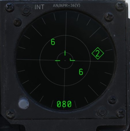
🚧 The ALR-46 is currently installed in the housing of a APR-36 earlier RWR model.
The resulting processed threat signal is then presented on the RWR's CRT display, with bearing to the emitter shown on the display with the top relative to the nose (12 o'clock) and the bottom the tail (6 o'clock), and with proximity to center relative to the system's calculation of the level of threat - with closer indications being of higher danger, and those within the middle ring being classified within engagement range. In normal operation, the ALR-46 can present 16 threats on the CRT concurrently. The highest priority threat as computed by the ALR-46's threat and range catalog is presented on the display with a diamond superimposed by its symbol; this is considered "floating" diamond functionality, with the ALR-46 defining priority. In the event of possible engagement by a threat emitter (concurrent with the illumination of the ACTIVITY and/or MISSILE LAUNCH buttons), the event is signified by a circle around the emitter symbol.
ALR-46 Controls
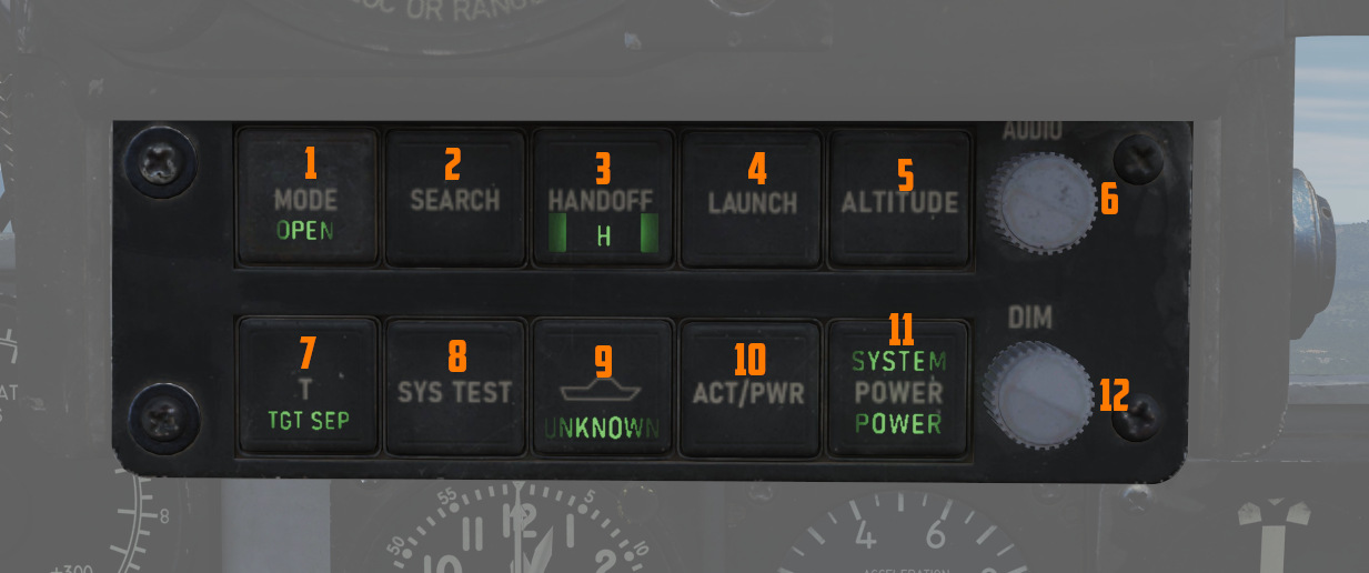
Controls are duplicated for pilot and WSO. The pilot controls are directly below the RWR Indicator, while the controls for the WSO are found below the Central Indicator in the front of the view.
RWR Display Intensity Knob
Found adjacent to the RWR situation display in the lower left corner of the panel, the Intensity Knob functions as a dimmer to control the brightness of the displayed RWR returns. Clockwise raises the brightness, counter-clockwise lowers the brightness.
ALR-46 Control Panel
The ALR-46 Control Panel consists of ten multipurpose, illuminated buttons, along with a pair of rotary knobs for controlling the system's volume and panel brightness.
Priority/Open
The ALR-46 defaults on power-up to OPEN mode (
S (Search)
By default, the ALR-46 is programmed to prioritize and display emitters tied to weapons that can
engage and destroy the aircraft. However, missions will require monitoring of early warning and
search radar systems working with longer pulse-widths for extended range detection and tracking of
possible intruders - i.e., the F-4. These emitters can be displayed using the Search mode
(
Because of their low threat priority, it is important to note that search radar symbology may often fall off the display due to their reduced importance - especially when the ALR-46 is placed into PRIORITY mode.
Handoff (H with <> Diamond)
The Handoff button (
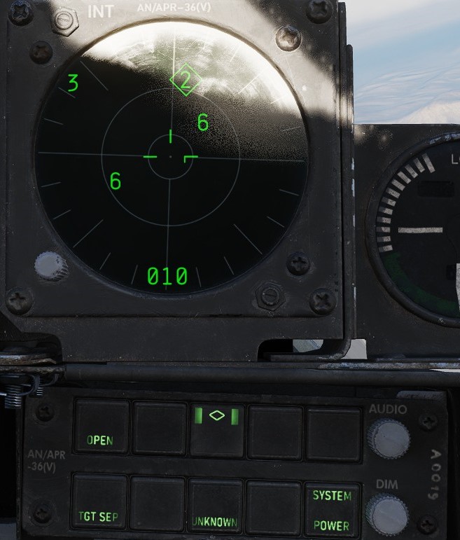
In the event that the emitter is tight grouping of other symbols on the display, the TGT SEP mode will be applied.
Missile Launch
In the event a missile launch is detected by way of discrete SAM guidance commands being received,
the MISSILE LAUNCH indications in this button (
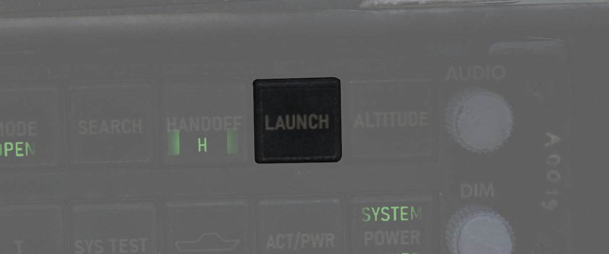
Low Altitude (LOW ALT)
The ALR-46 utilizes own-ship altitude as a defining aspect of threat priority, thus causing low
altitude AAA and SAM threats to lose priority in the event the aircraft is at an altitude that is
estimated to place it outside of their threat envelope. Activating LOW ALT mode (
Target Separate (TGT SEP)
In the event of a number of emitters being detected at such close proximity that the symbology
overlaps on the RWR display, the Target Separation button (
System Test (ON/SYS TEST)
The system power on test (
Unknown (U)
When an emitter is detected that does not have a catalog entry, but is recognized by received power,
duration, and pulse as being a possible threat, the U indicator on the Unknown button (
The default condition of the Unknown button is with the U symbol illuminated, but steady.
Activity Power
In the event SAM guidance commands are detected, the ACTIVITY button (
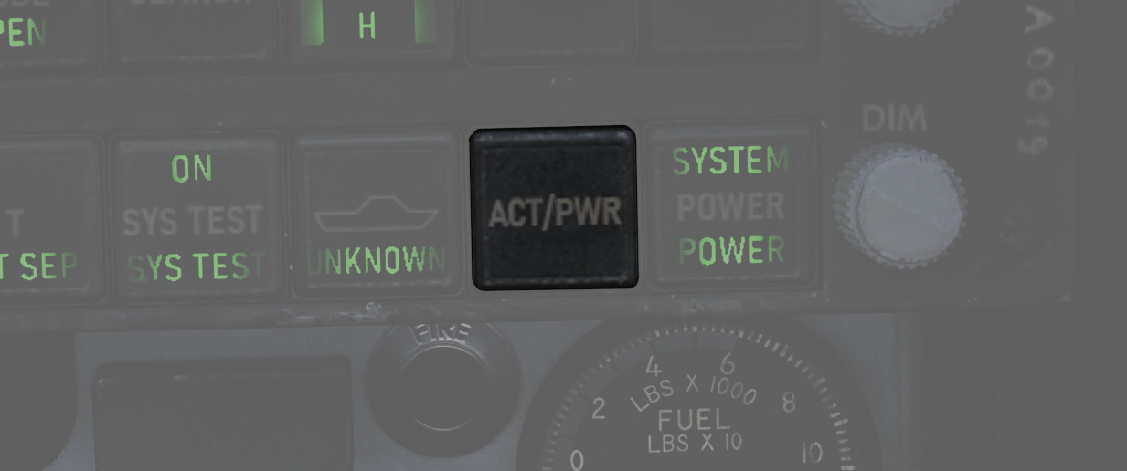
System Power
The System Power button (
In the event of a system power failure, the ALR-46 has an automatic restart function. Once power is recovered, the receiver will restart after a fifteen-second delay, in addition to its 9-second power on self test. The system will resume state in the same fashion as a normal restart - with Search mode deactivated and the altitude priority as when power was lost.
Excess Noise Strobe Indicators

During normal operation, a trio of three T shaped indicators appear in the 9, 12, and 3 o'clock
positions near the center of the RWR CRT. These indicators signify the absence of excess noise in
the low (
A fourth indicator may appear as part of the SYS TEST or power up cycle. This fourth indicator in the 6 o'clock position does not signify any function.
Audio Knob
The AUDIO Knob (
DIM Knob (Dimmer)
The DIM knob (
Symbology
The ALR-46 features a limited number of symbols for the different radar threats. The following
symbols can stand for the different threats. The ALR-46 can save up to three files containing threat
tables. Those three files contain either a Training set, a Land or a Sea set. The Training file is
not in use at the moment. The land file contains all land and air based threats while the sea file
contains all sea and air based threats. The Pilot can switch between the training and land file by
simply pressing the SYS TEST (
Land and Air based Threats
| Symbol | Possible threat |
|---|---|
 | SA-2 S-75 "Fan Song" TR |
 | SA-2 S-75 RD-75 Amazonka RF |
 | SA-3 S-125 "Low Blow" TR |
 | SA-5 S-200 "Square Pair" TR |
 | SA-6 Kub "Straight Flush" TR |
 | HQ-7 TR |
 | Osa 9A33 ln |
 | SA-10 S-300PS "Flap Lid" |
 | SA-11 9K37 Buk |
 | SA-15 9K331 Tor |
 | SA-19 2k22M Tunguska |
 | ZSU-23-4 Shilka |
 | Fire Can SON-9 |
 | Gepard, C-RAM Phalanx |
 | MIM-23 Hawk |
 | MIM-104 Patriot |
 | Rapier, Roland |
 | SA-6 Kub "Straight Flush" SR, Roland SR, C-Ram Phalanx SR, PPRU-1 "Dog Ear", HQ-7 SR, Hawk CWAR, NASAMS, Rapier Dagger, SA-11 Snow Drift, SA-10 "Big Bird", S-300PS 40B6MD SR |
 | E-2D Hawkeye, E-3C Sentry, A-50 |
 | F-14, F-15C, F-15E, F-16, F-18C, JF-17, M-2000C, Mig-29, SU-27, MiG-31, Tornado IDS/GR4 |
 | F-1, AJS-37, F-4E, MiG-19, MiG-21, MiG-23, F-5E-3 |
Sea and Air based Threats
| Symbol | Possible threat |
|---|---|
 | Rezky, Albatros |
| Battlecruiser Pyotr Velikiy, Cruiser Moskva, Type 052C Destroyer |
| Type 054A Frigate, Type 052B Destroyer |
 | Frigate Neustrashimy, CV 1143.5 Kuznetsov |
| La Combattante II |
 | Type 071, Leander Class |
| Ropucha Class |
 | CVN-71 Theodore Roosevelt, CVN-72 Abraham Lincoln, CVN-73 George Washington, CVN-74 John C Stennis, CVN-75 Harry S. Truman, USS Forrestral, LHA Tarrawa |
 | O.H. Perry |
 | Leander Class |
| Ticonderoga, USS Arleigh Burke |
| Rezky Head Net SR, Neustrashimy SR, Invincible SR, Leander SR, Slava Class SR, Kuznetsov SR, Ropucha SR |
| E-2D Hawkeye, E-3C Sentry, A-50 |
| F-14, F-15C, F-15E, F-16, F-18C, JF-17, M-2000C, Mig-29, SU-27, MiG-31, Tornado IDS/GR4 |
| F-1, AJS-37, F-4E, MiG-19, MiG-21, MiG-23, F-5E-3 |
AN/ALR-67 RWR
Description
The AN/ALR-67 radar warning receiver (RWR) is designed to inform and alert the F-14 crew about radar emitters in their general area. It’s also designed to help the crew defend themselves from hostile threats by indicating radar tracking and engagement by radar-guided weapons.
The AN/ALR-67 was integrated into the F-14 to replace the aging AN/ALR-45 and AN/ALR-50, at first for the F-14B and later for parts of the F-14A fleet. Until the advent of the PMDIG upgrade, the AN/ALR-67 used its own stand-alone display system only. The RWR is, however, connected to the AN/ALQ-126, allowing it to send info on threat emitters to the jammer and also display jammed targets on its own display. It can also trigger preprogrammed countermeasure programs set up in the AN/ALE-39 system.
On later F-14B aircraft incorporating the PTID upgrade, the AN/ALR-67 was also integrated into the MDIG displays system, allowing for a more detailed threat display on the ECMD.
The AN/ALR-67 on the F-14B has four small spiral high-band antennas, four wideband high-band quadrant receivers, and a low-band array. Connected to these antennas is a narrowband superheterodyne receiver analyzing the received signals and indicating emitters and threats to both pilot and RIO using two displays, one at each seat and by audio signals played to the ICS of both crewmen.
Controls

The AN/ALR-67 RWR is controlled by a control panel on the RIO right side horizontal panel.
- PWR (power) switch: Controls power to the RWR and should be set to ON to operate the system.
- VOL (volume) control knob: Sets RIO audio level for the RWR sound indications. The pilot has a corresponding control on his Volume/TACAN command panel.
- TEST switch: Has two selectable modes and is spring-loaded to center when not held. Momentary selection of the BIT position initiates the AN/ALR-67 built-in test and if the switch is held in the SPL (special) position while on the first BIT page displays the special BIT status page as long as it’s held in that position.
- MODE switch: Also has two selectable modes used while held in the respective position, spring-loaded to return to center when not held. When not activated, it enables normal operational mode, OFST enables the offset mode when held, and LMT the limit mode when held. The offset mode is indicated by an O in the status ring on the display and separates overlapping threat symbols sacrificing azimuth accuracy to instead show all threats clearly. The limit mode is indicated by an L in the status ring on the display and limits the display to only show the threat symbols of the six highest prioritized threats.
- DISPLAY TYPE selector: Sets what threat display priority to use on the RWR displays.
- NORM: Normal is indicated by an N in the status ring on the display and shows threat symbology according to the loaded threat library.
- AI: Airborne interceptor is indicated by an I in the status ring on the display and prioritizes all airborne interceptor threats above all other threats.
- AAA: Anti-aircraft artillery is indicated by an A in the status ring on the display and prioritizes all anti-aircraft artillery threats above all other threats.
- UNK: Unknown is indicated by a U in the status ring on the display and prioritizes all unknown threats above all other threats.
- FRIEND: Friendly is indicated by an F in the status ring on the display and allows for the same prioritization as in normal but also displays known friendly emitters.
Displays

The RWR display is identical at both positions in the cockpit and uses three bands (circles) on the display to indicate the threat level of the displayed threat symbols.
- Outermost, critical band: Displays threat symbols belonging to emitters representing an imminent threat to own aircraft, either a locked-on tracking radar or a radar detected to be actively engaging own aircraft. A threat symbol belonging to a track detected as actively engaging own aircraft is enhanced by flashing its symbol.
- Middle, lethal band: Displays threat symbols belonging to emitters representing threat systems deemed within lethal range of own aircraft but not actively tracking or engaging it.
- Inner, non-lethal band: Displays threat symbols belonging to emitters not representing a system capable of engaging own aircraft or systems capable of but not deemed within range to engage it.
- System status circle: Indicates various system modes in use or the presence of failures. The upper left quadrant displays what display type is set (N, I, A, U, or F), the upper right quadrant showing an L if limited display mode is used, and the lower half indicating either the use of the offset display mode by indicating an O, the presence of a BIT failure by showing B, or that the system is thermally overloaded (too warm) by showing a T.
- Display intensity knob: On the lower right side, it controls display intensity on the display it’s attached to.
Note: The ordering of the three threat bands has changed at least once since the introduction of the AN/ALR-67, and as the modeled AN/ALR-67 represents one of the earlier versions we’ve chosen the present order.
Warning Lights


The two crewmembers have warning lights dedicated to specific threats on their front cockpit panels. The pilot warning lights are situated on the right side of the HUD and the RIO warning lights on the right side of the TID. The RIO warning light panel also contains lights for the AN/ALQ-126 and the IFF transponder, those are detailed under their respective section.
The different lights illuminate to indicate the presence of a certain type of threat in the critical band of the RWR and when an active engagement is detected the corresponding light starts flashing. The categories present are SAM (surface-to-air missile), AAA (anti-air artillery), AI (airborne interceptor), and (only in the RIO pit) CW (continuous wave).
Threat Indication Alert Tones
The AN/ALR-67 uses four distinct audio tones to indicate threats and status changes of those threats.
- A single short tone is used to indicate the presence of a new emitter or when a threat is moved to another threat band.
- A slow warbling, alternating tone is used to indicate the presence of a threat in the critical band.
- A fast warbling, alternating tone is used to indicate that a threat is actively engaging own aircraft.
- A special four-tone audio signal, pitch decreasing with each tone, is used to indicate a special event as programmed by the threat library. In the Heatblur DCS F-14 this represents a new threat tied to a system capable of silently engaging own aircraft, i.e. it can engage own aircraft without causing its threat symbol to move to the critical band and thus no additional audio warning tones. This capability is either because the launching aircraft is capable of launching missiles in a TWS mode or that a launching SAM system can guide missiles by other means than radar and thus not giving further warning of an active engagement.
BIT

The AN/ALR-67 BIT cycles between different test screens testing the screen, symbology, and threat indication tones as well as displaying system revision and threat library information.
- The first page displayed shows system and threat library revision and the following screens test the symbol generation of the displays.
- The threat indication tones are also tested during the BIT, first page tests the status change tone, second page the special tone, third page the threat in critical band tone, and the fourth the fast warbling active threat tone.
- During the tests the threat warning lights also illuminate for both the pilot and the RIO.
Threat Symbology
The following table details the threat symbols used by the Heatblur DCS F-14 with the AN/ALR-67.
| Threat Symbol | Platform/Sensor | Special Tone |
|---|---|---|
| Ships (Symbology enhanced by being enclosed by an enlarged U symbol.) | ||
| AB | Arleigh Burke class destroyer | |
| AK | Admiral Kuznetsov class aircraft carrier | |
| GR | Grisha 5 class corvette (Albatros) | |
| HP | Oliver Hazard Perry class frigate | |
| J2 | Jiangkai II class frigate (Type 054A) | |
| KK | Krivak 3 class frigate (Rezky) | |
| KV | Kirov class battlecruiser (Pyotr Velikiy) | |
| L1 | Luyang I class destroyer (Type 052B) | |
| L2 | Luyang II class destroyer (Type 052C) | |
| LC | La Combattante IIa class fast attack craft | |
| N | Ships only carrying a navigational radar (civilian ships, submarines) | |
| NE | Neustrashimy class frigate | |
| NZ | Nimitz class aircraft carrier | |
| SV | Slava class cruiser (Moscow) | |
| TC | Ticonderoga class cruiser | |
| TT | Tarantul 3 class corvette (Molniya) | |
| TW | Tarawa class amphibious assault ship | |
| YU | Yuzhao class amphibious transport dock (Type 071) | |
| Aircraft | ||
| 14 | F-14A/B | Yes |
| 15 | F-15C/E | Yes |
| 16 | F-16C | Yes |
| 17 | JF-17 | Yes |
| 18 | F/A-18C | Yes |
| 19 | Mig-19 | |
| 21 | Mig-21bis | |
| 23 | Mig-23MLD | |
| 24 | Su-24M/MR | |
| 25 | Mig-25PD | |
| 29 | Su-27, Su-33, Mig-29A/G/S, and J-11A | Yes |
| 30 | Su-30 | Yes |
| 31 | Mig-31 | |
| 34 | Su-34 | Yes |
| 37 | AJS-37 | |
| 39 | Su-25TM (Su-39) | Yes |
| 50 | A-50 | |
| 52 | B-52 | |
| AN | AN-26B and AN-30M | |
| AP | AH-64D | |
| B1 | B-1B | |
| BE | Tu-95 and Tu-142M | |
| BF | Tu-22M3 | |
| BJ | Tu-160 | |
| E2 | E-2D | |
| E3 | E-3C | |
| F4 | F-4E | |
| F5 | F-5E | |
| HX | Ka-27 | |
| IL | IL-76MD and IL-78M | |
| KC | KC-135 | |
| KJ | KJ-2000 | |
| M2 | Mirage 2000-C and 2000-5 | Yes |
| S3 | S-3B | |
| SH | SH-60B | |
| TO | Tornado | |
| TR | C-130 and C-17A | |
| Air Defense | ||
| 2 | SA-2 Guideline Fan Song track radar (S-75) | |
| 3 | SA-3 Goa Low Blow track radar (S-125) | |
| 5 | SA-5 Gammon Square Pair track radar | |
| 6 | SA-6 Gainful Straight Flush track radar (Kub) | |
| 7 | HQ-7 track radar | |
| 8 | SA-8 Gecko search and track radar (Osa) | |
| 10 | SA-10 Grumble Flap Lid track radar (S-300PS 30N6) | |
| 11 | SA-11 Gadfly Fire Dome track radar (Buk) | |
| 15 | SA-15 Gauntlet Scrum Half search and track radar (Tor 9A331) | |
| 19 | SA-19 Grison Hot Shot search and track radar (Tunguska 2C6M) | Yes |
| A | Gepard, M-163 Vulcan, and ZSU-23-4 Shilka track radars | |
| BB | SA-10 Grumble Big Bird search radar (S-300PS 64H6E) | |
| BF | Rapier Blindfire track radar | |
| CS | SA-10 Grumble Clam Shell search radar (S-300PS 5N66M) | |
| DE | Sborka (Dog Ear) search radar | |
| FF | SA-2, SA-3, and SA-5 Flat Face search radar (S-125 P-19) | |
| GR | Roland MPDR-3002 S search radar | |
| HA | Hawk AN/MPQ-50 and AN/MPQ-55 search radars | |
| HK | Hawk AN/MPQ-46 track radar | |
| HQ | HQ-7 search radar | |
| NS | NASAMS AN/MPQ-64 Sentinel search radar | Yes |
| PT | Patriot AN/MPQ-53 search radar | |
| RO | Roland MPDR-16 search radar and Domino 30 track radar | |
| RP | Rapier Dagger search radar | |
| S | 1L13 and 55G6 early warning search radars | |
| SD | SA-11 Gadfly Snow Drift search radar (Buk) | |
| TS | SA-5 Gammon Tin Shield search radar | |
| Missiles | ||
| M | AIM-54, AIM-120, MICA-EM, R-37, R-77, and SD-10 | |
| ATC (Air Traffic Control) | ||
| T | Airport ATC Radar |
Note: Aircraft only flown by own faction in a mission are automatically set as friendly and shown only when setting the DISPLAY TYPE selector to FRIEND. N are shown only in UNK and T only in FRIEND.
ALR-45/50
Electronic Countermeasures - AN/ALQ-100 & 126 DECM (Defensive Electronic CounterMeasures)
The AN/ALQ-100 and 126 jammers are designed to detect radar threats, analyze them, select the optimum countermeasure technique available and apply it. Available techniques for jamming are, among others, mainlobe blanking, inverse con-scan, range-gate pull-off, and swept square modes.
In real life, these two systems differ greatly, with the AN/ALR-126 being by far the most effective system. In DCS, both are modeled as simple noise jammers due to engine limitations but controlled by the DECM logic as to when it’s on or off and thus work the same.
DECM Controls and Indicators
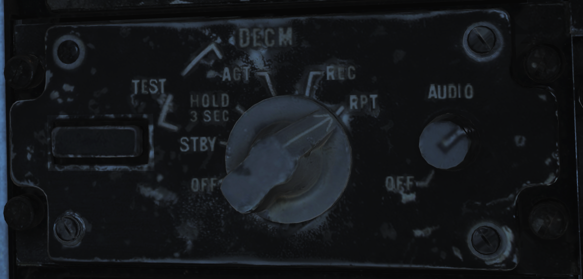
The controls for the DECM are all located on the right horizontal panel in the RIO pit, as shown in the image above. In addition, there are two indication lights co-located with the RWR threat indicators on the right side of the TID.
The two indication lights on the threat advisory are RCV (receive) and XMIT (transmit). RCV illuminates when the system detects and analyzes a threat, while the XMIT illuminates when it’s actively jamming a threat.
The control panel itself contains a STANDBY indicator light, a mode selector knob, and an AUDIO volume knob.
- The STANDBY light indicates that system warmup is not yet completed and turns off when completed. At other times, illumination of this indicator indicates the presence of a fault in the system.
- The AUDIO (volume) knob controls the audio volume of the RIO sound from the system. The pilot has no access to this audio. The audio itself is generated from the PRF of received threats with PRF frequency being converted to audio frequency.
- The mode selector knob controls power and operational mode of the system:
- OFF turns off power to the system.
- STBY begins pre-warming of the system, taking around 5 minutes.
- TEST - HOLD 3 SEC is used to prepare the system for BIT. After 3 seconds in this mode, turn the knob to TEST - ACT.
- TEST - ACT starts the BIT in the system. The BIT takes approximately 30 seconds, and the RCV light will be illuminated the whole time while the XMIT light will flash twice. If the STANDBY light illuminates, it indicates that a no-go condition exists in the system.
- REC enables the system in receive-only mode, enabling analysis of threats and also the threat audio.
- RPT enables full system functionality; in addition to REC, it also tries to jam threats according to the selected method.
Note: In DCS, jamming is always done with noise jamming, turning on as a threat is detected.
Emergency Systems
Warning and Indicator Lights
Telelight Panel
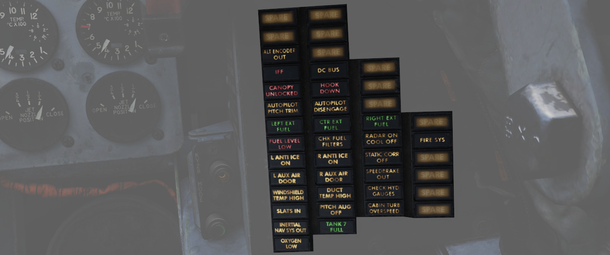
The majority of cockpit warning lamps are found on the telelight panel on the right sub-panel in the front cockpit. See the Emergency Procedures Supplement for a comapct list of them or see the one below:
| Light | Explanation | Light | Explanation | Light | Explanation |
|---|---|---|---|---|---|
| Alt Encoder out | The light will illuminate if there is an unreliable signal or no signal from the altitude encoder unit. It also may illuminate momentarily during high-rate climbs, dive maneuvers or during transonic flight | ||||
| IFF | The light will illuminate when the Mode 4 code is zeroed or no code is inserted | DC Bus | The light will illuminate if both generators fail or if a voltage drop occurs between the main dc bus and essential dc bus. | ||
| Canopy Unlocked | The light will illuminate in the front cockpit if any canopy is not locked and lowered. The rear light will only illuminate when the rear canopy is not fully locked and lowered. | Hook down | The light will illuminate if the arresting hook is not up and locked. | ||
| Autopilot Ptich Trim | The light will illuminate when the AFCS is engaged and the automatic pitch trim follow up is inoperative or lagging sufficiently behind the airplane maneuvering. | Autopilot Disengage | The light will illuminate when the autopilot is disengaged after initial engagement of the AFCS. | ||
| Left Ext Fuel | The light will illuminate if the external fuel tanks are selected and there is no fuel flow from the tank to the fuselage. | CTR Ext Fuel | The light will illuminate if the external fuel tanks are selected and there is no fuel flow from the tank to the fuselage. | Right Ext Fuel | The light will illuminate if the external fuel tanks are selected and there is no fuel flow from the tank to the fuselage. |
| Fuel Level Low | The light will illuminate when the Fuel level in cells 1 and 2 has reached a predetermined fuel state of 1650 ± 200 pounds. | CHK Fuel Filters | The light will illuminate when the fuel filter is clogged. The filter automatically opens to bypass, allowing normal fuel flow to the engine | Radar On Cool Off | |
| L Anti Ice On | The light will illuminate when the anti-ice bleed air system is on. | R Anti Ice On | The light will illuminate when the anti-ice bleed air system is on. | Static Corr Off | The light will illuminate if the SPC fails or the CADC switch is placed to CORR OFF |
| L Aux Air Door | The light will illuminate when the left auxiliary air door operates out of phase with the landing gear handle. | R Aux Air Door | The light will illuminate when the right auxiliary air door operates out of phase with the landing gear handle. | Speedbrake out | The light will illuminate if the speed brake is out or not fully closed. |
| Windshield Temp High | The light will illuminate when the windshield approaches a temperature which will cause optical distortion while the windshield rain removal is used. Windshield rain removal should be turned off immediately. | Duct Temp High | The light will illuminate when the temperature within the engine intake duct is beyond allowable limits. | Check Hyd Gauges | The light will illuminate if the pressure of any system drops below 1500 ± 100 psi. |
| Slats In | The light will illuminate if the Slats Override Switch is placed to the IN position, forcing the slats to stop moving as a function of the AOA. | Pitch Aug Off | The light will illuminate when power is on the airplane and the pitch stab aug switch is not engaged. | Cabin Turb Overspeed | The light will illuminate if the cabin turbine of the refrigeration unit is subjected to pressures and temperatures in excess of the normal operation. |
| Inertial Nav Sys Out | The light will illuminate if the Inertial Navigation system is either out or off. | Tank 7 Fuel | The light will illuminate when the fuel transfer valve fails to open. | ||
| Oxygen Low | The light will illuminate when the oxygen amount is below 1 litre. | Fire Sys | The light illuminates when either a fire/overheat detector sensor tube is burned through, a detector wire chafes to ground or the control module fails. |
Master Caution

Found in the front cockpit, the MASTER CAUTION provides the pilot with an up-front warning of potential hazard to the aircraft. The MASTER CAUTION illuminates concurrently with most warning lamps on the telelight panel and the generator indicators; warnings that do not set off MASTER CAUTION are noted in the Telelight Panel list.
MASTER CAUTION can be deactivated by the pilot pressing the reset button on the right console. However, it is important to note that pressing MASTER CAUTION does not clear a warning on the telelight panel; instead, the warning will remain until rectified. Should a second event occur in a system already giving a telelight warning, MASTER CAUTION will not illuminate a second time.
Warning Light Test Circuit
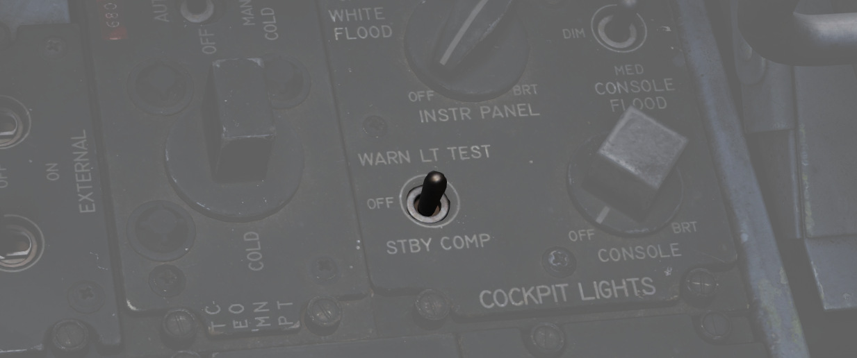
Confirmation of bulb function can be performed using the Warning Test Light Circuit found on the interior light control panel in both cockpits. These do not perform a function text for the individual warning systems, only confirm that the lights will illuminate.
Engine Fire and Overheat Detector System
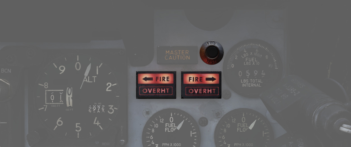
On the right upper instrument panel in the front cockpit are four warning lamps- two FIRE and two OVRHEAT lights, one for each side. Should a fire be detected in an engine compartment, the applicable FIRE lap will illuminate. Overheat detectors are mounted at the rear of the fuselage adjacent to the engine nozzles, and illuminate the respective OVRHEAT lamp should temperatures become dangerous to the aircraft.
Fire Test Button
When pressed, this button tests for functionality of the FIRE and OVRHT lamps. Can also be used in conjunction with the Warning Lights Test switch to confirm detection and continuity performance of the fire and overheat warning systems. Holding the Warning Lights Test switch in the WARN TEST position, then simultaneously pressing and releasing the Fire Test Button performs the test. Proper system function is confirmed with the four FIRE and OVRHT lamps off while the Fire Test Button is pressed, then illuminating when it is released.
Ejection Seats
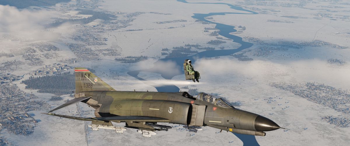
The Phantom II uses the Martin Baker Mk. H-7 ejection seat in both positions for safe aircrew extraction in the event of airframe loss. Triggering ejection using the face curtain or lower ejection handles fires the seat mounted initiator that jettisons the canopy. Once the canopy is clear of the airframe, the ejection gun primary charge fires, unlatching the seat from the cockpit and initiating seat climb-out. As the seat rises, restraints on the legs pull them back for clearance and the drogue timer is set. At the appropriate height, a lanyard attaching the rocket motor initiator to the airframe trips the firing pin for the main rocket engine to clear the aircraft. The previously set drogue gun fires at this time, deploying a pair of small chutes to stabilize the seat in attitude and initiate deceleration.
Once the seat has reached a pre-set barometric altitude between 11,500 and 14,500 feet, or momentarily after stabilization if lower, scissor mechanisms release the crew-member with the survival kit-containing seat pan from the ejection frame and deploys the main chute. In the event of ejection below the barostat altitude, the WSO chute is fully deployed at 5 seconds after ejection initiation, and the pilot one-second later.
Eject Light
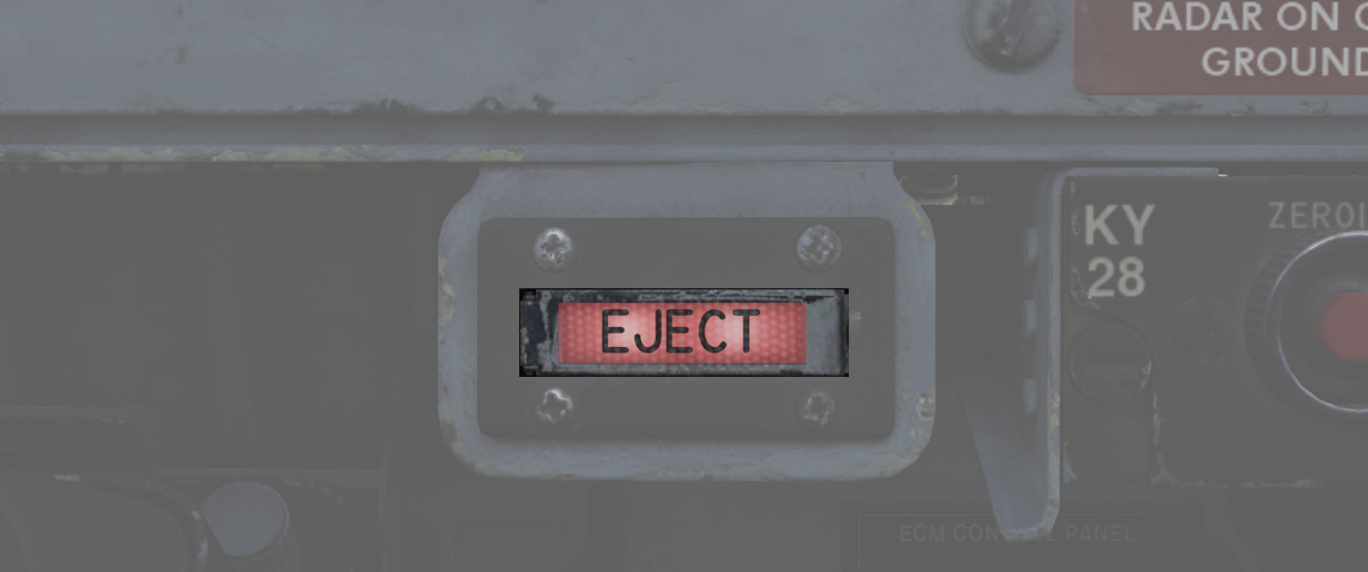
In the event of loss of intercom power, the pilot can warn the WSO to prepare for ejection by pressing the EJECT switch found on the left canopy sill forward of the flap switch. This illuminates a pair of warning lamps found on the rear cockpit indicator panel. This can also be done by the WSO to warn the Pilot of an ejection.
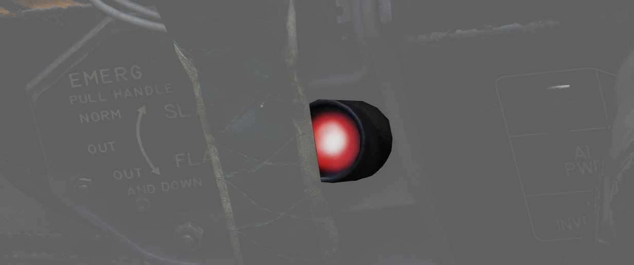
Command Selector Valve Handle

To the left and above the rear cockpit instrument panel is the Command Selector Valve Handle. This handle determines the sequence by an ejection initiated from the rear seat - both seats, or the rear seat only. The handle is marked PLT EJECT PULL TURN. When the handle is oriented vertically, single seat ejection is selected; to set dual seat ejection, the handle is rotated clockwise to the horizontal.
All ejections initiated from the front seat are dual ejections.
Jettison System

The majority of stores carried by the F-4 can be jettisoned from the aircraft while in flight and with the landing gear stowed and doors closed. Jettison does not remove pylons, and the AIM-9 Sidewinder is non-jettison-able.
| Name | Description |
|---|---|
| OFF | Safes PUSH TO JETT button on the Selective Jettison Control Panel. |
| STORES | Releases all MER/TER, single carried, LAU-88 mounted rounds, or drop tanks upon PUSH TO JETT. |
| L/R FWD | Jettisons AIM-7 from respective position on PUSH TO JETT. Inhibited if CL TK ON. |
| L/R AFT | Jettisons AIM-7 from respective position on PUSH TO JETT. |
| L/R WING | In conjunction with TV or ARM, jettisons single AGM-65 Maverick or AGM-45 Shrike from wing on PUSH TO JETT. |
External Stores Emergency Release Button
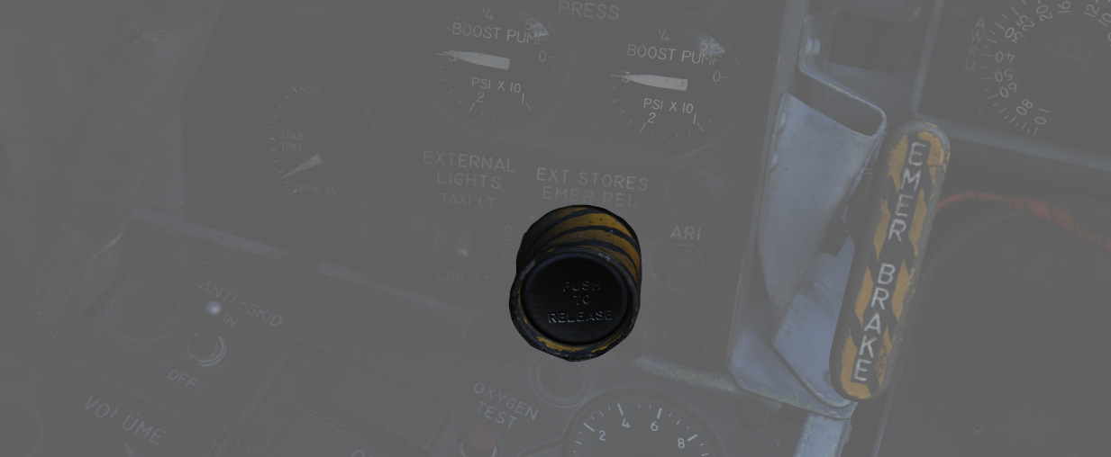
Found on the front left cockpit sub-panel, the External Stores Emergency Release, also known as the panic button, will release all air to ground munitions, external tanks, and any pods subject to jettison. Sparrow and Sidewinder missiles, along with all pylons, will remain in place. Pushing the button will show the yellow paint inside its recess to confirm its actuation. Performing the actuation disengages external fuel tank transfer automatically, permitting proper flow of internal wing tanks without further pilot action. The button is active so long as the aircraft gear is up, or, in the event of a forward gear handle failure, so long as the rear gear handle remains IN, and weight is off wheels.
Selective Jettison

Wing and centerline stores can be jettisoned independently using the Jettison Knob in the STORES position, selecting the desired Station Select Buttons to release, and pressing PUSH TO JET. Any pylon or missile launcher at the station will remain in place, but stores - including MERs and TERs, will be released.
As example, to jettison the right and left external fuel tanks, the pilot must select STORES on the knob, press the corresponding station select buttons LO, RO and then push the jettison button.
AIM-7 Jettison
AIM-7 Sparrow missiles are released individually using the L/R FWD or L/R AFT positions on the Jettison Knob, then pressing PUSH TO JETT.
AGM-65 Jettison
To release AGM-65 missiles, choose TV or ARM on the Weapon Select Knob, press the desired Station Select Button(s), select L WING or R WING for the Jettison Knob, and press PUSH TO JETT. One missile is released per press; once desired rounds are removed from one wing, select the other wing with the Jettison Knob and repeat the PUSH TO JETT cycle.
Weapons & Stores
As a cornerstone of air forces around the globe, the F-4E's effectiveness is not only attributed to its advanced avionics and airframe design but also to its formidable array of weapons and stores.
The F-4E features three main types of Air-to-Air Weaponry including Heat-Seeking Missiles with the AIM-9 in different variants, the semi-active radar homing missile AIM-7 in different variants and a M61A1 Vulcan cannon that can be used against Air and Ground Targets.
The aircraft can be armed with a variety of bombs, rockets, and guided munitions to engage and neutralize ground targets. Precision-guided munitions, such as laser-guided bombs, enable the Phantom II to strike high-value targets with precision, minimizing collateral damage and maximizing mission success.
In addition to its lethal armament, the F-4E can be configured with external fuel tanks to extend its operational range. The aircraft can also carry specialized stores, including targeting pods and electronic warfare (EW) systems.
Loadout
The following diagram gives an overview of all stores that can be loaded on the stations.
💡 In practice, not all combinations might be possible, as there are a lot of technical factors resulting in restrictions.
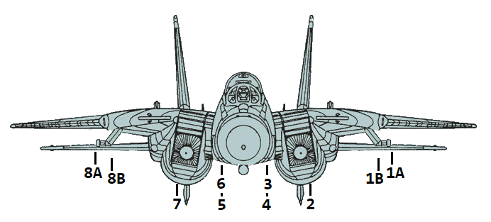
| Weapon Station | 1A | 1B | 2 | 3 | 4 | 5 | 6 | 7 | 8B | 8A | Total |
|---|---|---|---|---|---|---|---|---|---|---|---|
| AIM-9 | 1 | 1 | 4 | ||||||||
| AIM-7 | 1 | 1 | 1 | 1 | 1 | 1 | 6 | ||||
| AIM-54 | 1 | 1 | 1 | 1 | 1 | 1 | 6 | ||||
| Mk-81 | 2 | 4 | 3 | 3 | 4 | 2 | 18 | ||||
| Mk-82 | 2 | 4 | 3 | 3 | 4 | 2 | 18 | ||||
| Mk-82AIR | 2 | 4 | 3 | 3 | 4 | 2 | 18 | ||||
| Mk-82 Snake Eye | 2 | 4 | 3 | 3 | 4 | 2 | 18 | ||||
| Mk-83 | 1 | 3 | 1 | 1 | 3 | 1 | 10 | ||||
| Mk-84 | 1 | 1 | 1 | 1 | 4 | ||||||
| Mk-20 | 2 | 2 | 1 | 1 | 2 | 2 | 10 | ||||
| GBU-10 | 1 | 1 | 2 | ||||||||
| GBU-12 | 1 | 1 | 1 | 1 | 4 | ||||||
| GBU-16 | 1 | 1 | 1 | 4 | |||||||
| GBU-24 | 1 | 1 | 2 | ||||||||
| BDU-33 | 3 | 3 | 3 | 3 | 3 | 3 | 18 | ||||
| LAU-10 (Zuni) | 2 | 2 | 1 | 2 | 2 | 7 (28) | |||||
| ADM-141A TALD | 1 | 1 | 1 | 1 | 1 | 4 | |||||
| SUU-25 F/A Flare | 2 | 2 | 4 (16) | ||||||||
| LAU-138 Chaff Adapter | 1 | 1 | 2 | ||||||||
| Smokewinder | 1 | 1 | 4 | ||||||||
| TACTS | 1 | 1 | 2 | ||||||||
| LANTIRN | 1 | 1 | |||||||||
| FPU-1 Fuel Tank | 1 | 1 | 2 | ||||||||
| CNU-188 External Baggage Container | 1 | 1 | 2 |
M-61 Vulcan Six-Barreled Gatling Cannon
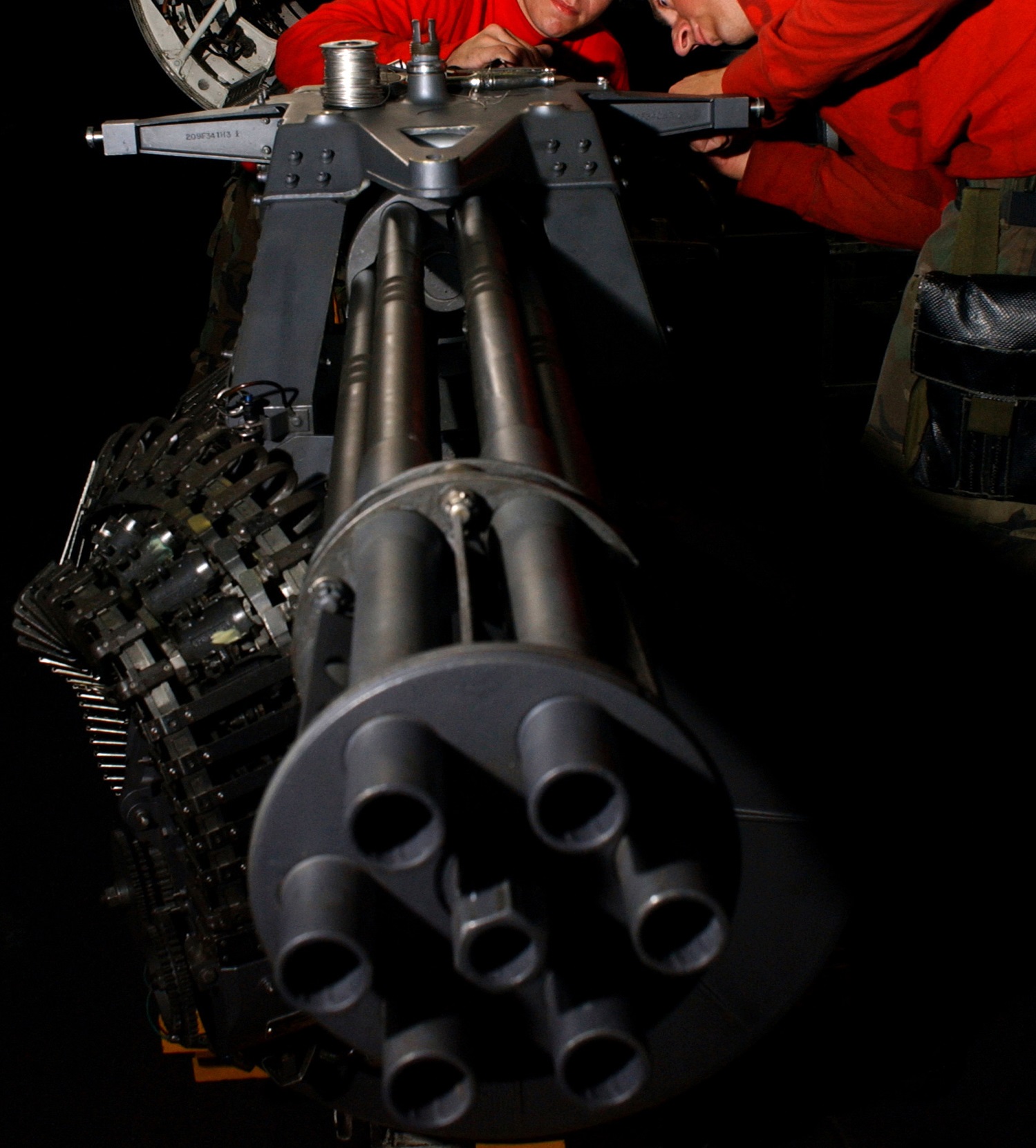 U.S. Navy photo by Photographers Mate Airman Kristopher Wilson. (041129-N-5345W-034)
The M-61 Vulcan is a six-barreled hydraulically driven 20 mm automatic cannon capable of firing over 6,000 rpm (rounds per minute).
The F-14 carries the gun internally mounted beneath the cockpit with the muzzle being located on the lower left side of the fuselage. 676 20 mm rounds are carried in the ammunition drum for the gun and retain the spent cases after the rounds have been fired.
The gun itself is mounted to be elevated slightly more than 3° from the ADL to provide built-in lead for dog-fight situations.
To fire the gun, no input is needed from the WCS, the gun can be fired by the trigger on the pilot stick when selected by the weapons selector on that same stick, provided master arm is on. The WCS can, however, provide symbology on the HUD to increase gun accuracy. For both air-to-air and air-to-ground modes the gun has two sights available. For air-to-air it’s the manual sight and the RTGS (real-time gun sight).
Selection of the gun is indicated on the bottom of the HUD by a capital G with remaining hundreds of rounds indicated below.
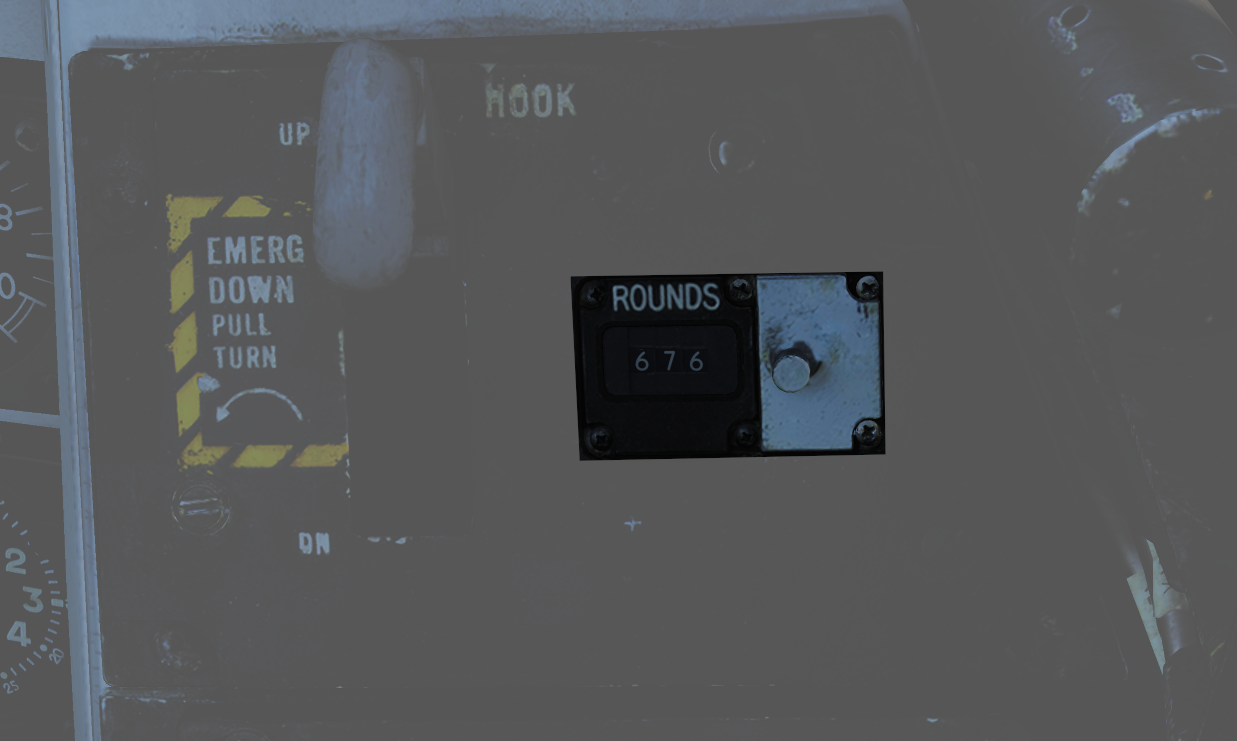 Apart from the indication on the HUD, the rounds remaining indicator on the pilot right vertical panel also shows remaining rounds. The indicator counts down from 650 but can manually be reset by rotating the knob below the indicator to the desired quantity.
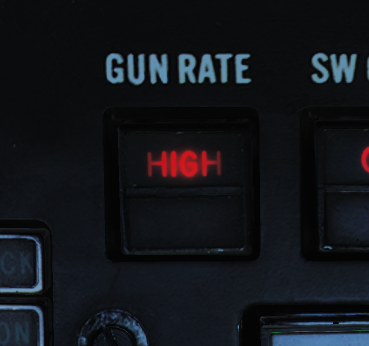 The gun is capable of a 4,000 rpm or 6,000 rpm mode. The lower rate is normally used for air-to-ground engagement and the higher rate for air-to-air engagement. The gun rate is selected by the GUN RATE switch on the ACM, which also indicates the selected option. Selection of ACM will set it to high automatically. The maximum number of bullets fired by a trigger pull can be set to be either 50, 100, 200, or unlimited. The default value is 200 bullets but can be set otherwise by the ground crew.
Note: In DCS this is set via the kneeboard.
Manual Air-to-Air Sight
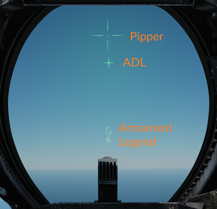 In manual mode, the HUD displays the ADL, the armament legend, and the manual pipper. This mode is accessed by depressing and releasing the CAGE/SEAM pushbutton on the left throttle when in the air-to-air mode with the gun selected. In this mode, the pilot has to manually aim the gun using the manual pipper as a reference to hit the target. Real target range and needed deflection need to be estimated by the pilot.
The manual piper is adjustable to enable the selection of the desired lead. The GUN ELEV panel on the pilot right vertical panel sets the lead; normally, this should be set to 53 milliradians to place the manual pipper on the gun sight line.
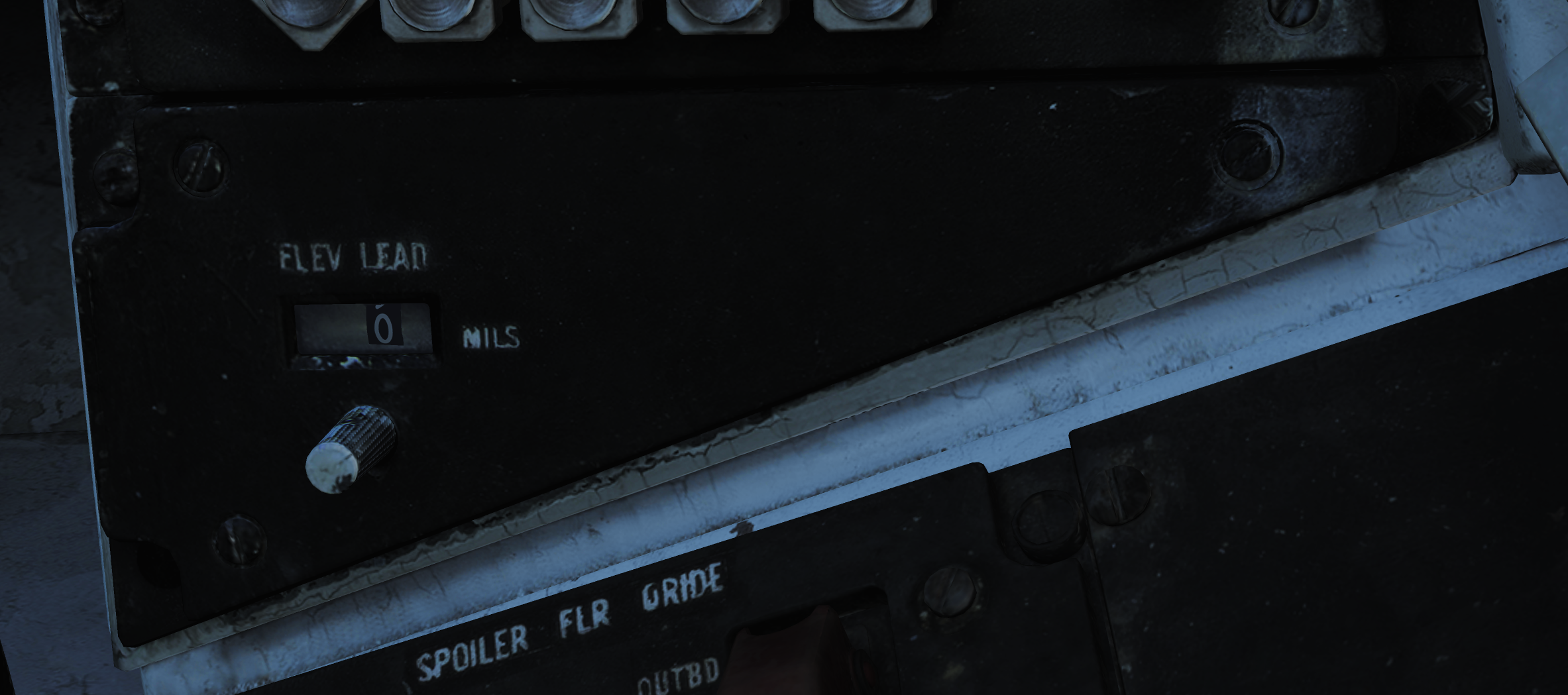
Real-Time Gunsight (RTGS)
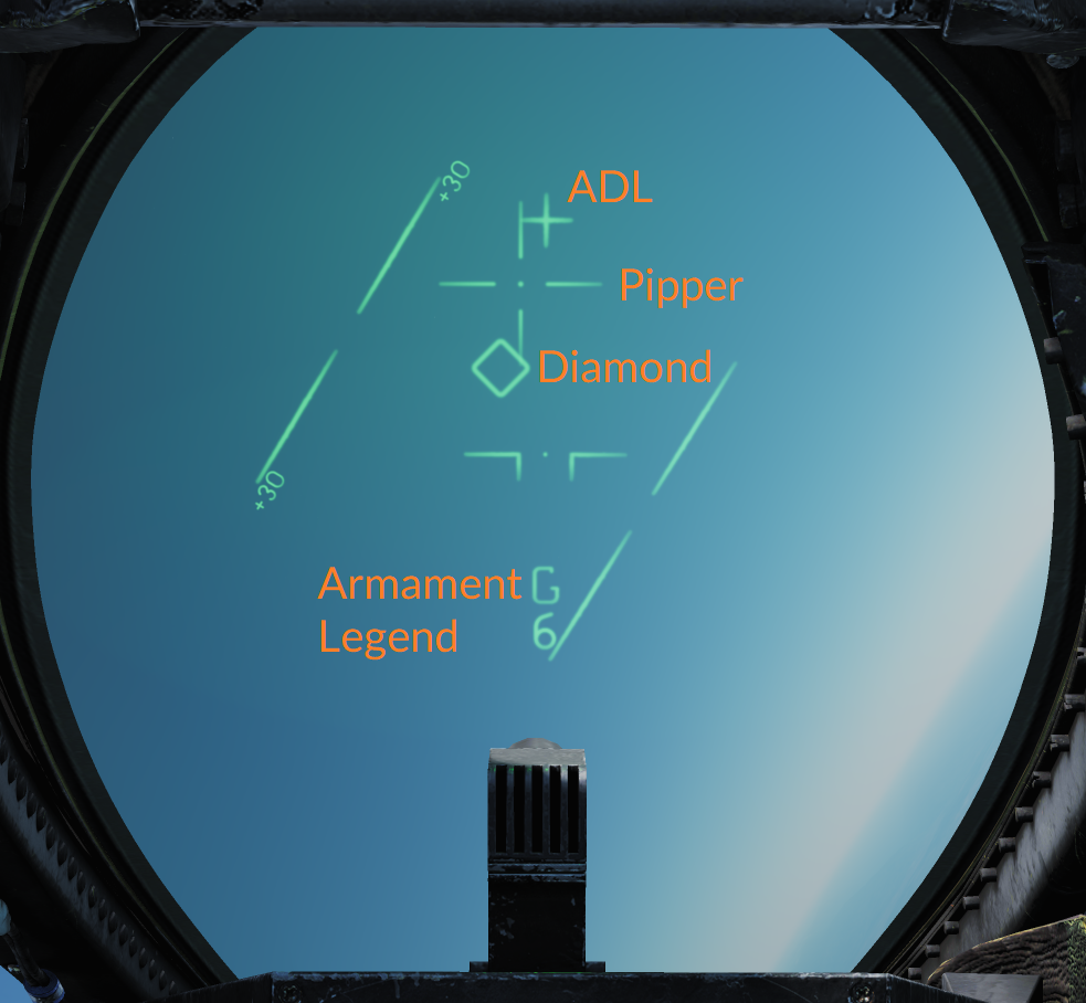 The real-time gunsight mode is the standard gun mode when in the air-to-air mode with the gun selected.
In RTGS, the WCS computes the bullet trajectory and displays the location the bullets will pass through at 1,000 and 2,000 feet, if no target data is available from the WCS. The pipper represents bullet location at 1,000 feet and the diamond represents the bullet location at 2,000 feet.
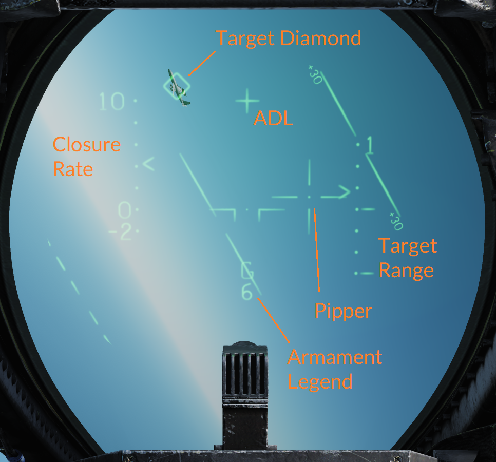 If target data is available from the WCS (target tracked in an STT mode), the pipper instead displays bullet location at the target’s current range out to 4,000 feet. The diamond will display radar line of sight to the target (target location). This means that when having a target track, the pilot should fly the aircraft to place the pipper over the target to hit it.
In addition to computing the solution to put bullets at the target's location, the RTGS sight will also calculate where the bullets actually are in relation to the target when at target range. When the bullets fired are computed to be at the target’s location, the diamond switches from target indication to indicating bullet position at target range (BATR). This is also indicated by the diamond flashing.
Using this symbology, it’s possible to see where the target would have needed to be to be hit by the bullets. If the gun engagement was executed successfully, this means that the diamond should still be on top of the target, blinking, indicating that the bullets passed through the target’s location.
Manual Air-to-Ground Sight
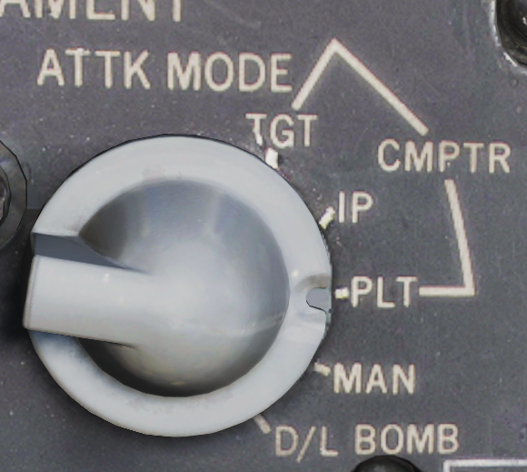 The manual air-to-ground sight works and looks the same way as the manual air-to-air sight except that it’s set by the RIO using the ATTK MODE selector on the armament control panel that’s located on the RIO left vertical panel. Selecting MAN on that selector enables the same HUD symbology as in the manual air-to-air sight upon the selection of the air-to-ground mode, the only additional HUD symbology being the display of the radar altitude on the right side of the HUD. The gun deflection should instead be set according to a pre-calculated setting depending on airspeed, target range, and dive angle.
Computer/Pilot Mode
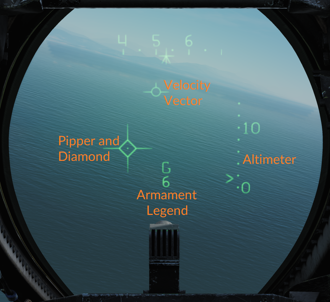 Computer/pilot mode is used to have the WCS continuously compute a weapon impact point for, among other air-to-ground weapons, the gun. It is set by the RIO on the ATTK MODE selector, as for manual air-to-ground sight, by selecting CMPTR-PLT.
In this mode, the AN/AWG-9 radar is slaved to the weapon impact point for accurate range measurements and enables the HUD display of that same impact point.
The HUD uses the pipper to indicate a real-time weapon impact point and the diamond to indicate out of range. When the diamond disappears, the gun is in range to engage a target under the pipper. The pull-up cue moves vertically on the HUD and when it’s at or above the weapon impact point (pipper), it indicates that an immediate pull-up is required to avoid striking the ground and that the target is too close to engage safely.
The right side of the HUD displays the barometric altitude scale.
Mixed Gun Mode
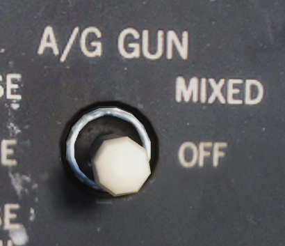 The gun can also be used at the same time as another air-to-ground munition is selected by setting the A/G GUN switch on the armament panel (on the RIO left vertical panel) to MIXED. This enables the trigger to fire the gun but no HUD symbology is available for the gun as it’s being used to display release data for the selected munition. In this mode, the pilot needs to estimate the gun impact point manually with the ADL as the only reference on the HUD.
Air to Air
HUD Symbology for Air-to-Air Missiles

The above image shows the HUD with Phoenixes selected while in air-to-air display mode.
As standard the HUD shows the Closure Rate on the left side in hundreths of knots, from -200 to +1,000 knots. Current closure rate as displayed by a <.
Additionally it displays the Target Range Scale on the right side, showing target range at the displayed scale, 10 NM in this case as display at the upper end. The target range scale shows the current target range with a > and selected weapon max and minimum ranges as indicated by the dashes (-).
The Movable Reticle (called pipper for air to ground and gun employment) and the Target Designator can show different things depending on current situation.
The Movable Reticle shows current TCS line of sight if it exists at the same time as a radar STT lock except for when AIM-9s are selected. In the AIM-9 case it instead shows current AIM-9 seeker head line of sight.
The Target Designator diamond shows current radar STT line of sight if present and if not it instead shows the current TCS line of sight.
So effectually the TCS line of sight can be shown either by the movable reticle or the target designator depending on if a radar STT is also present and if a radar STT is present with AIM-9 selected it’s not shown at all.
AIM-7 Sparrow
 U.S. Navy photo by Photographer’s Mate 3rd Class Joshua Karsten. (041108-N-8704K-008)
The AIM-7 Sparrow air-to-air missile is a supersonic boost-glide missile capable of engaging both aircraft and missiles in all weather conditions. The AIM-7 Sparrow missile is a medium-range air-to-air missile with a max range of at least 16 NM (30 km) for the AIM-7E and at least 38 NM (70 km) for the AIM-7F and AIM-7M. The all-weather capability comes from the missile being radar-guided, more exactly SARH (semi-active radar homing). This means that the seeker of the Sparrow relies on the AN/AWG-9 painting the targets for it and following the radar emissions being reflected off the target.
The F-14 can carry the AIM-7E, AIM-7F, and AIM-7M on four dedicated recesses on the aircraft fuselage and one each on the glove pylons.
Apart from the various improvements to the missile range, seeker, and warhead, the major difference between the different versions is that the AIM-7F and newer missiles can also be guided via pulse doppler illumination in addition to CW as opposed to only CW.
Missile Preparation
 Before launch, the AIM-7 missiles need to be prepared by the selection of the MSL PREP-ON pushbutton on the pilot ACM panel. This commands the WCS to start missile preparation for the AIM-7 and AIM-54.
In the case of the AIM-7, the WCS applies electrical power to the missile to pre-heat the electronics and gyros. It also injects CW radar video from the radar to the missiles via an emitter on the aft end of the rail to a receiver at the aft end of the missile. This video is used to tune the AIM-7 missile to the selected CW frequency on the RIO DDD panel. When the individual missiles are tuned and ready, the corresponding missile status windows turn white to indicate a ready missile.
Launch Modes
The two available launch modes for the AIM-7 on the F-14 are the normal mode and the boresight mode. To select the AIM-7 for launch, the pilot selects the SP/PH (sparrow/phoenix) position on the stick weapon selector. Selection of which Sparrow to launch is done automatically by the WCS.
Depression of the weapon selector switches from SP to PH and vice versa. If an STT target is available, the WCS will automatically use the normal mode for launch unless BRSIT (boresight) is selected on the MSL MODE (missile mode) switch on the ACM panel. In all other cases, the boresight mode will be used.
Normal Mode
 As the normal mode is used to engage a target tracked in STT, the WCS is capable of using both CW and pulse doppler for guidance. When using CW in the normal mode, the AN/AWG-9 radar uses a dedicated CW antenna to spotlight the tracked target more directly than via the flood antenna. While CW is the normal guidance mode for all AIM-7 variants, it is possible to select the pulse doppler guidance mode instead when using the AIM-7F and AIM-7M missiles.
This is done on the RIO's armament panel with the MSL OPTIONS switch by setting it to SP DP (sparrow doppler). When selected, this causes the WCS to guide the Sparrow missiles using pulse doppler illumination instead.
Regardless of guidance mode, the WCS calculates the missile LAR (launch acceptance region) and displays the missile launch ranges on the VDI and TID. The HUD shows the target diamond and current target range, Rmin and Rmax, while the VDI, DDD, and TID display the attack guidance symbology as well as the above-mentioned missile LAR indications.
Boresight Mode
The boresight mode uses the CW flood antenna on the AN/AWG-9 radar and will cause the missile to track the strongest target return within the flood area. In addition to when launched in boresight mode, the radar will also switch to flood mode when a target is lost, either before launch or after launch, enabling the pilot to try and save the shot by keeping the target within the flood area.

AIM-9 Sidewinder
 U.S. Navy photo by Photographer’s Mate Airman Kristopher Wilson. (050112-N-5345W-066)
The AIM-9 Sidewinder is a short-range air-to-air missile. It uses an infrared seeker locking on to a target's IR signature, making it capable of tracking a target both during daytime and at night.
The F-14 Tomcat is capable of carrying all Navy versions of the AIM-9 Sidewinder from the AIM-9D up to the AIM-9M. The Heatblur F-14 Tomcat is currently modeled as carrying the AIM-9L and AIM-9M.
The F-14 is capable of carrying the AIM-9 on stations 1A & B and 8A & B. Stations 1 & 8 are the glove pylons, which can each carry two AIM-9s for a total of 4. Station 1A & 8A are dedicated to carry only the AIM-9 and are normally used when only carrying two to allow station 1B & 8B to carry other munitions.
Missile Preparation
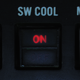 The cooling of the AIM-9 seeker head needs to be enabled before launch. This is done by pressing the SW COOL switch on the pilot ACM panel or by selecting the ACM mode on the same panel. This commands cooling of the missile's seeker head. The missile will immediately show ready, but full seeker head performance will take at least 60 seconds.
Seeker Head Modes
The AIM-9G introduced a seeker head capable of the Sidewinder expanded acquisition mode (SEAM), and all later Sidewinders carried by the F-14 are also capable of that mode. SEAM allows the missile seeker head to be uncaged to track a target within the seeker limits (40° from ADL), allowing the pilot to lead the target, improving missile performance. It also allows for the WCS on the F-14 to slave the seeker to a tracked target within 20° from ADL, allowing for off-boresight acquisition.
The AIM-9 on the F-14 can still use the old boresight mode where the seeker head remains slaved to ADL (2.5° field of view), but normally SEAM is used to scan the seeker about either ADL or a tracked target. This scan is not visible to the pilot and is done to increase effective seeker head field of view. As with all Sidewinders, target detection is indicated by an aural tone. That growling tone is present while scanning but increases in intensity while the seeker is looking at an IR source.
Missile Operation
The AIM-9 Sidewinder is selected for launch with the weapon selector on the pilot stick. The weapon selector can be used to cycle which AIM-9 is selected for launch by depressing it, indicating on the ACM panel which missile is selected by a checkerboard indication in the corresponding status window. When using the AIM-9, the HUD uses the diamond to indicate a tracked target and the pipper (crosshair) to indicate current seeker head position. If a WCS track with range is available, the HUD also displays range to target and Rmin and Rmax. The VDI, DDD, and TID display the attack guidance symbology if a WCS track is present.
The basic missile boresight mode without SEAM (no scan) is commanded by depressing the BRSIT (boresight) switch on the pilot ACM panel while not having the ACM mode active. In this mode, the pilot puts the target at ADL and fires when the aural tone is present.
If the BRSIT switch is not used or the ACM mode is active, the AIM-9 will use the SEAM and set the missile to use the double-D scan pattern. If a WCS target is present, the seeker head will scan around the radar or TCS line of sight; otherwise, the missile will scan around the ADL.
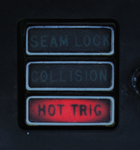 To enable lock-on to a target in SEAM, the pilot depresses the CAGE/SEAM pushbutton on the left throttle. This illuminates the SEAM LOCK light on the ACM panel and uncages the seeker for 4.5 seconds, allowing it to track a target present in the seeker's field of view. If no IR source is found, the missile is again caged and the SEAM LOCK light is deactivated.
If lock-on is successful, the aural tone will remain and the SEAM LOCK light stays illuminated, allowing the pilot to launch the missile by pressing the stick trigger. After launch, the next AIM-9 will automatically be selected.
AIM-54 Phoenix
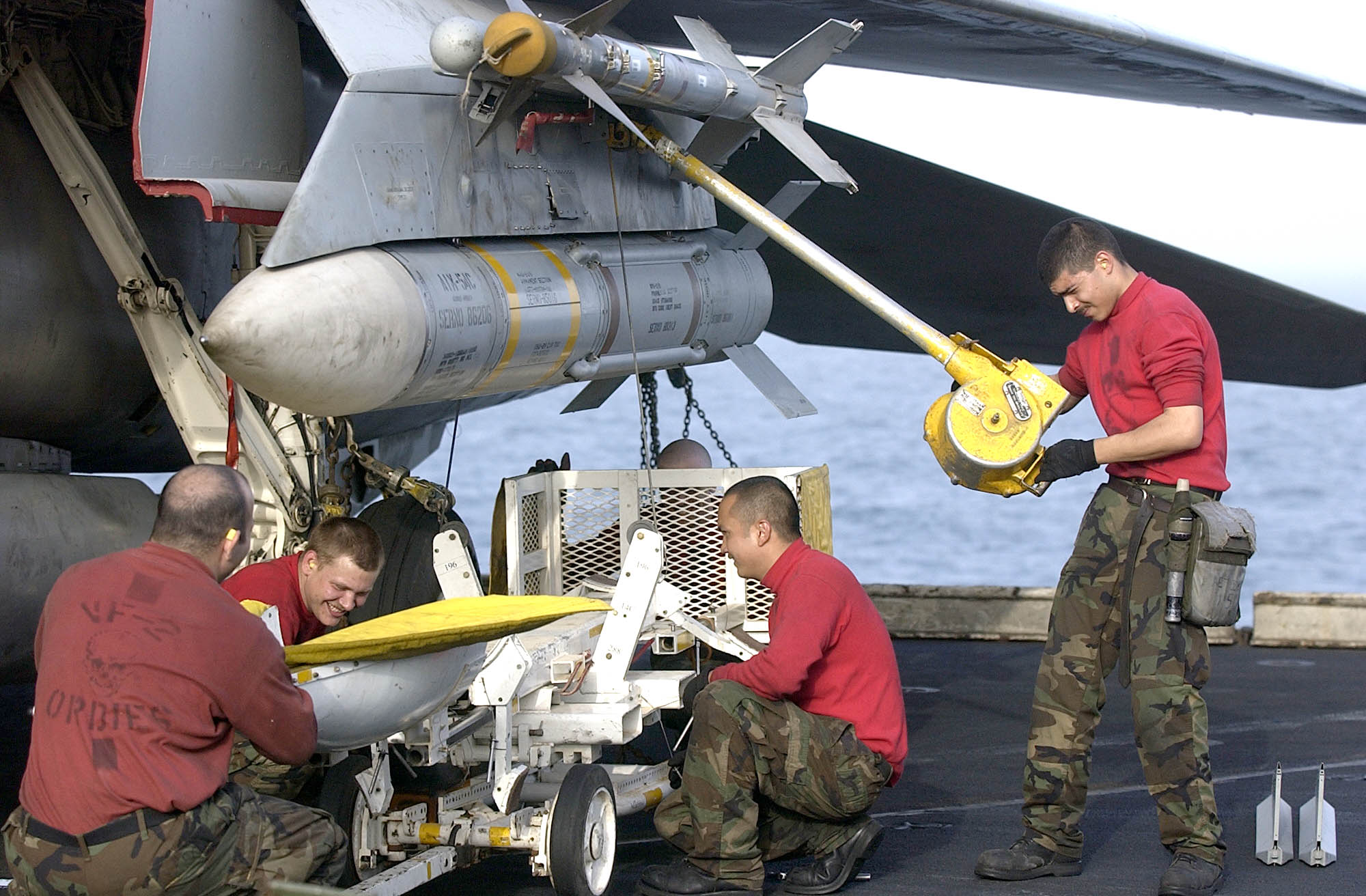 U.S. Navy photo by Photographer’s Mate 2nd Class Felix Garza Jr. (030320-N-4142G-013)
Note: Depicted missile has yet to have the forward fins attached.
The AIM-54 Phoenix is a long-range air-to-air missile originally designed for the F-111B fleet air defense fighter, which never materialized. When the F-111B project was scrapped, the AIM-54 and the corresponding AN/AWG-9 WCS eventually found their way to the F-14.
The F-14 is capable of carrying up to 6 AIM-54 missiles, four on rails on the fuselage and one each on the glove pylons. Because of the missile cooling system used, the two front Phoenix pylons must always be mounted, meaning that the rear fuselage pylons can’t be used if the front ones aren’t present. The glove pylons contain their own cooling systems.
The missile is capable of engagement both against a single target in STT and multiple targets using track-while-search (TWS).
The AIM-54 is available in two different versions, the AIM-54A and the AIM-54C. The Heatblur Simulations F-14 Tomcat models both versions as well as the AIM-54A with both mk47 and mk60 rocket motors. The two motors on the AIM-54A differ in effective range, while the AIM-54C differs by having a digital seeker instead of an analog one, increasing its performance, as well as an improved, smokeless mk47 rocket motor.
The AIM-54 has a range of at least 60 NM against a fighter-sized target at high altitudes in pulse doppler STT. When using TWS for engagement against multiple targets, this drops to about 50 NM. It has a greater range against large targets and vice versa against smaller targets.
If launched in active mode, the range drops to about 10 NM for a fighter-sized target, varying slightly with target size. Notably, the missile will revert to SARH mode if no target is detected if selected for active launch in a SARH mode.
Missile Preparation
The AIM-54 missile preparation is started by selecting the MSL PREP switch on the pilot ACM panel or by activating the ACM. This enables power and cooling to the missile and also starts the built-in tests in the missile (BIT).
As with the AIM-7, the AIM-54 is tuned before launch using a transmitter on the rear end of the missile rail, transmitting to the rear receiver of the missile. The whole missile preparation cycle is completed after around 2 minutes, at which time the AIM-54 missiles are indicated ready in the corresponding missile status windows on the pilot ACM.
Launch Modes
The seeker head used in the AIM-54 is capable of both semi-active radar homing (SARH) and active radar homing (ARH).
Normally, the launch to eject (LTE) cycle of the missile is 3 seconds, meaning the time from trigger depression to missile ejection. The exception is the ACM active mode, where the LTE is shortened to 1 second if within 15° from ADL.
TWS SARH/ARH
In TWS, the AN/AWG-9 is capable of supporting the launch of up to 6 AIM-54 missiles against 6 different targets concurrently. In the first stage of the AIM-54 engagement, the missile is guided semi-actively by the AN/AWG-9 radar using both guidance commands transmitted via the radar and radar energy reflected off the target. Then, when the missile is within range of its seeker’s ARH mode, the AN/AWG-9 commands the missile to switch to ARH.
Absence of this command via the AN/AWG-9 radar means that the missile won’t switch to the ARH mode. The AN/AWG-9, however, continues to transmit guidance commands to the missile as a fallback in case the missile can’t acquire the target autonomously. This means that the AIM-54 isn’t a “fire and forget” missile per se, but it can be considered autonomous after transfer to ARH.
PD STT SARH
In pulse doppler STT, the AIM-54 uses SARH all the way to the target, receiving guidance commands at a greater rate than in TWS and also continuous spotlighting of the target because of the STT mode being used. This increases the effective range of the AIM-54 seeker slightly.
Active-Radar Homing (ARH)
 The AIM-54 can also be commanded to go active directly after launch in both TWS and pulse doppler STT modes by setting the MSL OPTIONS switch to PH ACT before launch. This tells the WCS to immediately command the AIM-54 to go active in the first guidance command after launch. If launched at a target within 6 NM in the target's rear hemisphere or 10 NM in its forward hemisphere, the WCS will also automatically command this mode instead of a SARH mode.
If the target is not detected actively by the seeker, it will still fall back to SARH until the seeker can acquire on its own, like in the two SARH modes.
Note: Setting the MSL OPTIONS switch to PH ACT with an AIM-54 in the air will not make it go active; the PH ACT option can only be set before missile launch.
ACM Active
The last mode is ACM active, in which the missile is commanded active before launch, making this the only mode where the missile is truly fire and forget. The AIM-54 missile receives the active message before launch from the WCS in addition to a command prepositioning the seeker head to have it look at the current WCS track if available.
ACM active is commanded when BRSIT (boresight) is selected on the pilot ACM panel, when having the ACM active without a WCS track, and when using a non-pulse doppler radar mode or TCS track. When using boresight or ACM without a track, the missile will launch along the ADL, locking onto the first target seen while launching at a non-pulse doppler radar track, the seeker head will be prepositioned onto that track.
ECM Mode
In all of the guidance modes, the seeker head automatically switches to a passive ECM follow if jammed, angle-tracking the target until it can again track the target using SARH or ARH. This is done without crew action and is not indicated to the operator.
Missile Operation
The AIM-54 missile is selected with the weapon selector on the pilot stick by selecting the SP/PH (sparrow/phoenix) position and then depressing the selector to switch from SP to PH. It is possible to switch back to SP by again depressing the weapon selector.
When used in boresight or ACM without a WCS track, the HUD will not indicate any symbology apart from the ADL, which is used to aim the missile.
When selected with a WCS track in STT, the HUD will display the Target Designator, and if a TCS track exists, the Movable Reticle overlaying the target, the former indicating WCS track and the latter TCS line of sight. The range scale on the right side of the HUD indicates range to target and Rmin and Rmax, while the VDI, DDD, and TID display the attack guidance symbology.
TWS
When using the AIM-54 with TWS, the WCS automatically prioritizes the tracked targets, giving them a firing order number indicating missile launch order. As the first target is launched at, the first track’s number is removed, and the other tracks’ numbers are decreased by one.
To continue to engage tracks 2 through 6, the pilot depresses the trigger once for each target, waits until the missile is clear, and then depresses the trigger again for the next missile, and so on until the desired number of missiles are away.
After missile launch, the prioritization numbers on the right side of the targeted tracks are replaced with the TTI or Time to Impact number, showing calculated time until missile hits the target.
Additionally, when the AN/AWG-9 has sent the active command to the missile, the TTI numbers blink, indicating that the missile targeting the track has been commanded to active mode. When this happens depends on the setting of the TGTS switch on the DDD. SMALL equals 6NM, NORM equals 10NM, and LARGE equals 13NM. The setting set before launch is used.
The targets currently under missile attack brighten until estimated time to target plus 15 seconds has elapsed, and when at 15 seconds past estimated time to the last target, the break-away cross is also displayed on the VDI, DDD, and TID.
For more info regarding the applicable TID symbology, see TID Symbology.
 It is possible to force the WCS to include a target by setting it to mandatory attack using the CAP and also to exclude a target by setting it to do not attack on the same panel. In addition, it is possible to command the WCS to set a track as priority 1 in the firing order by hooking it and pressing NEXT LAUNCH on the RIO armament panel.
If not already in TWS AUTO, the WCS automatically switches to this mode, thus assuming control over the AN/AWG-9 radar to keep the engaged targets illuminated. In addition to the track numbering, the TID also displays a steering centroid indicating the center weight of the TWS scan pattern.
The HUD and VDI display a steering cue guiding the pilot towards optimal target illumination and also display range and Rmin and Rmax to target number 1. The TID displays the complete attack symbology with target prioritization numbers and individual optimum launch ranges. For more info, see Track While Scan (TWS).
AIM-54 in DCS
The HB DCS F-14 includes custom AIM-54A and AIM-54C missiles, the AIM-54A with a choice of two different rocket motors. The aerodynamics and engine performance for these missiles have been extensively researched and computer simulated to make the included missiles behave as realistically as possible in regards to aerodynamics.
Regarding missile seeker and flight profile, we’ve worked with Eagle Dynamics to enable our F-14 AN/AWG-9 to control the AIM-54 to a degree. In DCS, this means the following:
In TWS, the missiles will fly out using guidance from the AN/AWG-9 until about 16 seconds to impact, at which time the AN/AWG-9 will tell the missile to go active if it’s still within the radar scan zone. The exact distance at which the AN/AWG-9 sends the ATC depends on the setting of the TGTS switch, as detailed above. This results in a silent engagement until the missiles go active, at which time the target’s radar warning receiver will get an indication of an active missile engaging it. If fired at range, the AIM-54 will loft for greater range. Setting the different seeker activation ranges impacts the amount of warning the target will get but also the amount of time the missile needs to be supported.
In PD-STT (Pulse-Doppler Single Target Track), the AIM-54 will be launched in a pure semi-active mode and be guided in that mode all the way to the target without going active. This means that the engaged target will get an immediate engagement warning through its radar warning receiver from the AN/AWG-9 as soon as the AIM-54 leaves the rail. Like in TWS, the missile will loft if fired at range.
For all other modes and within 10NM of the target (or in ACM or PH ACT), the AIM-54 will launch active off the rail, and the targeted aircraft will immediately see the missile’s own radar actively engaging it. It will not loft in this case, and thus the range is less than in the other two cases.
The AIM-54C in DCS currently is not affected by the Target Size Switch.
Air to Ground
Despite being primarily designed as an air superioty fighter and an interceptor the F-14 was from the very start cleared and tested to carry all of the modern American general purpose bombs (GP) of the Mk-80 series. In addition it was also cleared to carry the Mk-20 Rockeye cluster bomb and the 5” Zuni folding-fin aircraft rocket (FFAR).
As the F-14’s combat role changed to include the precision ground attack mission it was also cleared to carry several of the guided bomb unit (GBU) versions of the Mk-80 series bombs, more specifically, some of the laser guided versions.
Air-to-Ground Weapon Settings
 The air-to-ground weapon delivery is set up by the RIO on his armament panel on the left vertical panel of the RIO cockpit.
The type of munition for delivery is set up by the wheel on the top of the panel, turning it to the correct munition. This configures the WCS with the correct parameters for the selected munition.
Note: The Mk-81, 82, and 83 have both an L and an H option for low-drag and high-drag versions, respectively.
Under DLVY MODE (delivery mode), it is possible to set STP/RPL (step/ripple) and SGL/PRS (single/pairs). The possible combinations are:
- STP and SGL: Releases one store with each depression of the bomb release button on the pilot stick.
- STP and PRS: As with STP and SGL but each depression of the bomb release button on the pilot stick releases a pair of stores. Only works for paired stations, 1 with 8, 3 with 6, and 4 with 5.
- RPL and SGL: Used with all attack modes, each depression of the bomb release button on the pilot stick releases a set amount of stores set by the QTY (quantity) wheels with the interval set by the INTERVAL wheels (in milliseconds).
- RPL and PRS: As RPL and SGL but each release pulse releases a pair of stores, QTY still sets the total amount of stores to be released.
The MECH FUSE switch sets which mechanical fuse to arm on the stores. NOSE arms the nose fuse, SAFE inhibits arming of the fuses, and NOSE/TAIL arms both fuses.
The ELEC FUSE selector knob sets the electrical fuse of the store to be released:
- SAFE: Inhibits electrical bomb fusing.
- VT: Sets air-burst mode at preset burst height for compatible stores.
- INST: Sets instantaneous burst mode.
- DLY 1: Sets preset time delay 1.
- DLY 2: Sets preset time delay 2.
The INTERVAL and QTY (quantity) wheels set the release interval (in milliseconds) and quantity of stores to be released, compatible with the delivery modes as seen above under DLVY MODE.
Lastly, the 6 STA SEL (station select) switches set which pylons to use for store delivery (also used for selection of what stores to jettison). To select a pylon for store delivery, set the corresponding switch to SEL. Stations 1 and 8 should be set to B for selection, SW was used to jettison AIM-9 Sidewinders but is now inoperable.
Note: All F-14 bombs in DCS are assumed to have both types of fuzes, so both the mechanical and electrical fuze need to be set. GBUs, Mk-20s, and Mk-81 to 84s need the mechanical fuze set to either N or N/T settings, the Mk-82AIR (ballute) and Mk-82 Snake-Eye can be dropped in free-fall with N and retarded with N/T.
Air-to-Ground Weapon Delivery
Air-to-ground delivery is initiated by pilot selection of the A/G mode on the display control panel. After tape read-in (about 30 seconds), the WCS initiates the air-to-ground mode and enables relevant symbology on the displays.
The weapon selection automatically switches to ordnance (ORD on the HUD) unless the pilot has selected another weapon. All other options are set by the RIO in the back seat.
The available attack modes in the F-14 are set by the ATTK MODE selector in the RIO pit and are:
- CMPTR TGT: Computer target, a semi-automatic computer-guided mode similar to a CCRP mode in newer aircraft.
- CMPTR IP: Computer initial point, an extended CMPTR TGT mode using a known initial point (IP) as a reference for store delivery. Mostly used in situations where the actual target is expected to be hard to locate visually and is located closely to an easily identifiable reference point/landmark.
- CMPTR PLT: Computer pilot, a manual computer and pilot-guided mode using the WCS for store impact point indication on HUD. Similar to a CCIP mode in newer aircraft.
- MAN: Manual, manual backup mode in which the HUD displays a pipper (crosshair) on the HUD at the deflection set by the pilot. Used in case of a systems failure prohibiting the other modes.
- D/L BOMB: Data-link bomb, an automatic mode in which the pilot is steered via data-link cues for remotely controlled store delivery. (Not implemented in DCS at this point in time.)
Computer Target
 The computer target mode allows the pilot to designate a target onto which the WCS then guides the pilot towards store release. This mode is usable for all air-to-ground stores, including rockets.
When selected, the HUD displays the diamond as target designator and the bomb fall line (BFL) through the velocity vector and store impact point pipper (crosshair).
To designate a target, the pilot steers the aircraft in azimuth to place the target along the BFL. Then UP/DN on the target designate switch on the left wall of the pilot cockpit is used to slew the target designator along the BFL until it overlays the target. At that point, the target is designated by pressing the target designate switch to DES.
After designation, the target designation diamond becomes stabilized to the designated position on the ground, and the AN/AWG-9 is slewed to it for range measurements. The BFL now remains overlaying the designated target while the store impact point pipper and aircraft velocity vector continue to follow aircraft movements. In addition, the HUD now displays the upper and lower solution cues on the BFL.
The pilot should now fly the velocity vector and store impact point over the BFL until the solution cues reach them. The lower solution cue indicates imminent store release when passing the velocity vector, and the pilot should by now be holding the bomb release button depressed to authorize WCS store release. When the upper solution cue reaches the velocity vector, the WCS automatically releases set stores on the condition that the bomb release button is depressed.
The pull-up cue (bracket on the HUD) moves upwards on the HUD towards the velocity vector with decreasing altitude. When it reaches the velocity vector, it indicates that the aircraft is below safe altitude for store release.
Computer Initial Point
Functionally identical to the Computer Target mode except that a preset initial point (IP) is designated instead of the actual target. The IP is preset before takeoff using data-link or manually by the RIO using the CAP.
The IP waypoint should be a terrain feature expected to be visually identifiable by the pilot even if the target is not.
To set the CAP, the RIO designates the location of the IP waypoint as per the other waypoints in the system. (See CAP heading under AN/AWG-9 in the General Design and Systems Overview section or the Navigation Systems heading in the same section)
The message (function) IP TO TGT on the CAP under the SPL category is then used with the prefixes ALT, RNG, and BRG to read out and set the following data points:
- ALT: Sets altitude difference of the target relative to the IP waypoint.
- RNG: Sets range to target from the IP waypoint.
- BRG: Sets the bearing to the target from the IP waypoint.
When the pilot designates the IP visually on the HUD, the WCS recalculates the target location using the data set under the IP TO TGT function on the CAP, moves the target diamond to that location, and instead displays guidance towards the real target location.
All other functions of this mode are identical to the Computer Target mode.
Computer Pilot
 The computer pilot mode uses the WCS to continually calculate and display an impact point for the configured store on the HUD.
When selected, the HUD displays the current store impact point in real-time using the pipper (crosshair). The target designation diamond is used when the WCS is configured for rockets and overlays the pipper to indicate that the configured store is out of range when displayed. As in the Computer Target and IP modes, the pull-up cue is used to indicate aircraft below safe store release altitude when at or above the velocity vector.
To correctly engage the desired target, the pilot flies the impact point pipper on the HUD over the target and then depresses the bomb release button.
When using rockets, the pilot should wait until the diamond disappears, indicating that the selected store is within range and then use the control stick trigger to fire the rockets.
Manual
 The manual air-to-ground mode is used as a backup when the other modes are unavailable.
By principle, it works the same as the Computer Pilot mode in that the pilot should fly the pipper on the HUD over the desired target. The pipper is in this mode not updated by the WCS, however, but instead set at a deflection from the ADL according to desired engagement speed, dive angle, and release altitude.
This is set using the elevation lead panel on the pilot right side vertical panel using weapon engagement tables or by pilot estimation.
Zuni Rockets
The Zuni 5-inch folding-fin aircraft rocket (FFAR) was developed to replace the high-velocity aircraft rocket (HVAR) of World War 2 vintage. As part of its design, it’s modular and capable of using different warheads as well as different fuzes.
The Zuni rockets are carried in LAU-10 pods, each carrying 4 rockets. The pods can fire in either salvo mode or ripple mode, salvo launching one rocket and ripple all.
The F-14 Tomcat can carry LAU-10 rocket pods on stations 1B, 3, 6, and 8B using TERs, each TER holding up to two pods except one of either 3 or 6 which must only carry one as not to clash with a pod on the adjacent station. The TERs are used to gain separation from the station for safe rocket firing, and the reason for not being able to use three pods on the TERs is that on the glove pylons, the inner TER station would conflict with the main landing gear and on stations 3 and 6 with the fuselage.
The Zuni rockets are set up for launch by the RIO on the armament panel as with bombs, the delivery mode (DLVY MODE) switches being used to configure how many pods to activate at a time.
Mk-81, 82, 83, and 84 GP Bombs
 U.S. Navy photo by Photographer’s Mate Airman Justin S. Osborne. (030321-N-0382O-506)
The Mk-80 series bombs are the standard general-purpose bombs used by the US Navy and allies and were first dropped in combat during the Vietnam War. The Mk-82 also has the capability to mount a retardation system using either folding fins or an inflated ballute to brake the bomb after release, allowing them to be dropped at lower altitudes as the dropping aircraft has more time to move away from them. Those versions are called the Mk-82 Snake Eye (fins) and Mk-82AIR (ballute) in DCS.
The F-14 is capable of carrying all the various bombs in the Mk-80s series, 81 through to 84. While the ground attack mission never really materialized for the F-14 in the Navy, it was tested for and cleared to deliver these weapons from the start.
The F-14 uses the Phoenix rails (stations 3-6) and the glove pylons’ lower stations to mount the bombs. The rails themselves can carry all four variants while the 81 to 83 can also be mounted on substations along the sides of the Phoenix rails as well as on TERs on the glove pylons.
All of the Mk-80 bombs have nose fuzes only and should be dropped with the nose (N) fuze setting on the mechanical fuze switch on the RIO armament panel. The Mk-82AIR and Snake Eye variants use the tail fuze wire to enable bomb retardation, meaning that the nose/tail (N/T) mechanical fuze option should be used if retardation is needed.
The total amount of the different bombs carried depends on weapon weight and weapon clearance between the rails; the actual number varies from 18 for the 81s and 82s to just 4 for the 84s as those can only be mounted on the rails themselves. For more info, see the F-14 loadout diagrams.
GBU-10, 12, 16, and 24
 U.S. Navy photo by Photographer’s Mate Airman Milosz Reterski. (040105-N-9742R-001)
The GBU (guided bomb unit) are bombs from the Mk-80s series with an attached seeker unit and fin (control) unit converting them into guided precision bombs, and in the case of the GBU-10, 12, 16, and 24 carried by the F-14, laser-guided bombs to be more precise.
When the F-14B gained the ability to mount and use the LANTIRN pod, it was also cleared to carry some of the GBU variants of the Mk-80 series bombs. It can either deliver them onto designation from a self-carried LANTIRN pod or onto a laser designation from another aircraft or ground source.
The GBUs carried are mounted on the Phoenix rails themselves on stations 3-6 as the additional size of a GBU compared to a normal Mk-80 series bomb makes it impossible to use the substations on the rails for those. Each station is capable of carrying one GBU up to the size of the GBU-16. As for the GBU-10 and 24, the 10 can be carried on the front rails (3 and 6) and the 24 on one front rail and one back rail as they need to be carried on opposite sides of the aircraft due to the larger wing assembly.
Note: GBU laser codes are set as per DCS Mission Editor Functions Specific to the HB DCS F-14 or via the kneeboard.
Mk-20 Rockeye
The Mk-20 Rockeye is a conventional free-fall bomb like the Mk-80 series bombs, but instead of a conventional charge, it carries anti-tank submunitions. The Rockeye contains 247 of these anti-tank submunitions, which are released at a set height using a radar altimeter, the design being that the submunitions are dispersed over a large area for greater effect.
The fuze height itself is set by the ground crew as they’re loaded and can’t be changed by the pilot. To arm the Rockeye correctly, the mechanical fuse should be set to nose (N).
The F-14 can carry up to 10 Mk-20 Rockeyes using the Phoenix rails and substations as well as TERs on the glove pylons.
Note: Additional fuse settings (FMU-140 fuse) pending additional weapon code implementation.
BDU-33 Practice Bombs
The BDU-33 practice bomb is a training round used to simulate a Mk-82 general-purpose bomb for training purposes. They can be carried three to a TER on each of station 3, 4, 5, and 6 on the F-14 Tomcat.
They are set up for release as with the real general-purpose bombs.
ADM-141 TALD
 U.S. Navy photo by Photographer’s Mate 3rd Class Mark J. Rebilas. (041018-N-6213R-021)
The ADM-141 tactical air-launched decoy (TALD) is a gliding decoy simulating real aircraft using active and passive means. There are several versions of the TALD, examples being a version equipped to launch chaff and another version using a Luneberg lens to increase its cross-section to simulate a larger aircraft.
All versions are pre-programmed before takeoff and are unpowered, gliding through the air on fold-out wings.
The F-14 can carry up to four ADM-141 TALDs, one each on stations 3 through 6, using a TER each to gain separation from the aircraft fuselage.
Note: In DCS these currently glide straight ahead until they run out of speed and altitude.
LUU-2 Parachute Flare
The LUU-2 parachute flare is an air-launched flare suspended by a parachute used to illuminate the ground during nighttime.
The F-14 can carry up to 16 LUU-2 flares in up to 4 SUU-25 flare dispensers on TERs at stations 4 and 5, each TER capable of carrying up to 2 dispensers in order not to conflict with the fuselage.
The LUU-2 parachute flare is launched and set up in the same way as a general-purpose bomb.
Smokewinder
The Smokewinder is a smoke pod used for aerial displays simulating an AIM-9 missile to the aircraft interface.
To enable and disable a Smokewinder, select AIM-9 for launch using boresight (BRSIT) and select the corresponding weapon station using the weapon selector on the pilot stick. When set up thusly and with master arm on, each pull of the trigger enables or disables the Smokewinder discharging smoke.
Pods
TACTS Pods
The TACTS pod is an analysis pod used during training missions, carried on LAU-7 rails instead of AIM-9s, normally on station 1A and 8A. They are normally carried as a pair of two, one on each side.
Note: In DCS, their functionality is purely cosmetic.
LANTIRN
 U.S. Navy photo by Photographers Mate Airman Jason Frost. (030122-N-9403F-002)
The LANTIRN was adapted for use on the F-14 Tomcats during the 1990s as the F-14’s role started to gravitate towards including the precision strike role.
The version carried on the Heatblur DCS F-14B Tomcat represents the earliest integrations of the LANTIRN, the pod being carried only on station 8B and hardwired to the control panel in the RIO cockpit and to the video input on the TID/VDI.
For more information regarding the use of the LANTIRN pod, see the section about it under the General Design and Systems Overview chapter.
Tanks
FPU-1 Fuel Tank
The FPU-1 fuel tank is carried by the F-14 Tomcat on stations 2 and 7 on each engine nacelle. They each carry up to 2,000 pounds of fuel and can be jettisoned in the same way as other stores using the normal procedures.
Jester
"You not only get a weapons system officer, folks. You get yourself an admin officer, you get yourself a flight planner, you get yourself a watchdog, and he carries a full array of maps and pubs."
Flying the Phantom is already a challenge in itself - doing that alone even more.
Jester is your AI buddy who can take the role of the WSO, so that you can focus on doing that pilot stuff.
--
The Jester AI aims to be a functional AI radar intercept officer (RIO) for the Heatblur DCS F-14, enabling a multicrew experience in a single-player (per aircraft) environment.
He is fully integrated into the rear cockpit, controlling nearly all back seat systems with a focus on systems not controllable from the pilot seat. He is also modeled to take into account the limitations of a real human, meaning that his current head position, visual spotting range, and what his hands are doing are fully modeled. When controlling the systems at the RIO seat, he performs all actions that a human RIO would have to do.
To order/control Jester, a command wheel is used for quick access. This wheel is dynamic depending on the current mode selected and also on the current situation. Feedback to the pilot from Jester is via the ICS using a library of recorded audio, simulating the experience of having a RIO actually talking to you. Apart from acknowledging orders, he will also communicate pertinent information to the pilot depending on the situation.
Finally, in a multiplayer environment, a RIO joining a Tomcat in flight will find all controls at the rear seat in the position where Jester left them. If the human RIO disconnects, Jester will resume control of the systems in the configuration the human player left them.
--
🚧 This section is under construction
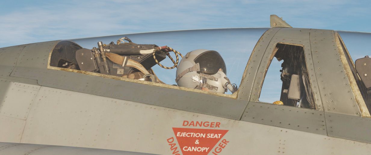
Among his responsibilities are:
- providing assistance during take off, aerial refueling and landing
- assisting with navigation
- helping in operating the countermeasures
- operating the radar
- controlling the targeting pod
- spotting other aircraft and missiles
and more...
Functionality

The Jester menu is by default brought up using A and selection of a menu item (1 to 8) is done using CTRL + 1 to 8. These key commands can be changed or set to a controller using the Jester category under F-14 Pilot in the DCS keybinds. The key commands for the menu petals are designed to be mapped to an eight-way hat on a game controller. Additionally, it’s possible to use the viewing angle in the cockpit to select a petal while holding the Jester menu keybind for more than 0.5 seconds. This can be enabled or disabled in the F-14 options.
Pictured above is the main Jester menu, which contains all the different available contextual menus. The first press of the Jester menu command normally brings up one of the contextual menus depending on the mode and situation the aircraft is in. For example, air-to-air mode while airborne lands the user directly into the BEYOND VISUAL RANGE - RADAR menu, while airborne and in air-to-ground mode brings up the AIR TO GROUND - WEAPONS menu. In addition, the take-off and landing modes have their own contextual menus only available when in those modes.
After pressing the Jester menu command and landing in the relevant contextual menu, another press of the same command then brings up the main Jester menu, enabling selection of a different contextual menu than the automatic one.
The normal sequence of pressing the Jester menu command (defaulting to A) is thus: Menu OFF -> Contextual menu depending on mode and situation -> Main Menu -> Menu OFF.
From these menus, it is then possible to control the various systems at the RIO seat. Depending on previous commands, options in the different contextual menus might change, and some systems use the petals of the menu as inputs/keypads to set frequencies and other numbers in those systems.
For example, it is possible to tell Jester to set a waypoint in the navigational systems, but it will require a lot of consecutive key presses. As a shortcut, it is possible to have him enter a waypoint from a map marker set in the F10 view. To help with selecting a marker in this case, the menu will show the user time since created and the name entered for the marker.
In the case of a system needing to select a specific symbol, like choosing a target on the TID to lock in STT, the menu will allow the pilot to tell Jester to either lock the closest target, the closest hostile target, and so on. Additionally, it is possible to specify a specific symbol/track to look using an azimuth/range system.
Lastly, Jester is also able to read out the startup checklist, helping the pilot to cold start the F-14 in the assisted startup detailed further down.
Navigation
🚧 This section is under construction
Navigation with Jester revolves around managing turn points for two flight plans: the Primary Flight Plan and the Secondary Flight Plan. Both can be edited and followed by Jester in the same manner, although Primary Flight Plan is considered the main one and the Secondary Flight Plan serves as a backup.
Flight Plan
A flight plan consists of multiple turn points. They can be inserted, deleted or edited by the player through the UI, map or mission editor.
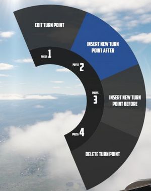
If the mission has assigned the aircraft a series of waypoints through the mission editor, this will be available by default as the Primary Flight Plan.
Map Marker
Using the F10 map view in DCS, players can create named markers on the map simply by double clicking the desired position after selecting Mark Label at the top row in the UI.
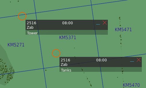
Through the UI, these map markers can then be imported as turn points to the flight plan.
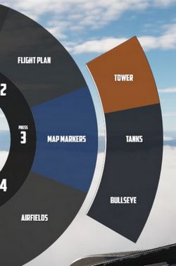
Tune Asset
The UI offers a list of nearby assets, such as ships, tankers or ground stations.
Their current position can be imported as turn point directly.
💡 For moving assets like tankers, their actual position might vary from the planned coordinates. Use TACAN or ADF for more precise navigation.
Tune Airfield
Similar to tuning for assets, the UI provides a list of nearby airfields to navigate to.
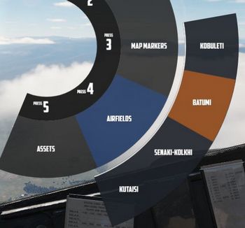
Enter Coordinates
One way to add a turn point is by entering the corresponding LAT/LON through the UI.
The format is H DD MM H DDD MM,
- where
Hrepresents the hemisphere (NorSfor latitude andEorWfor longitude); Dsignifies Degrees (00to89for latitude and000to179for longitude);- and
Mstands for Minutes (00to59).
A valid example could be N 45 32 E 047 12 or S 05 55 W 105 00.
💡 Spaces are optional,
N4532E04712is also valid.
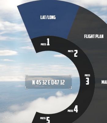
Operation
Jester navigates by utilizing a technique called leapfrogging. The aircraft only provides a single slot to memorize a waypoint (called TGT 2).
Planned Route
When leapfrogging, TGT 2 always indicates the next turn point of the current active flight plan. As the aircraft approaches this turn point (±2 nautical miles), Jester will automatically update TGT 2 to the next turn point in the sequence.
This enables the pilot to follow the entire route of the flight plan by selecting NAV COMP on the Navigation Function Selector Panel and following the corresponding indication on the HSI.
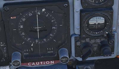
Divert
Besides following the flight plan, Jester is capable of diverting to a different unplanned turn point using TGT 1.
Through the UI, players can switch between the diversion (TGT1) and flight plan (TGT2) at any time.
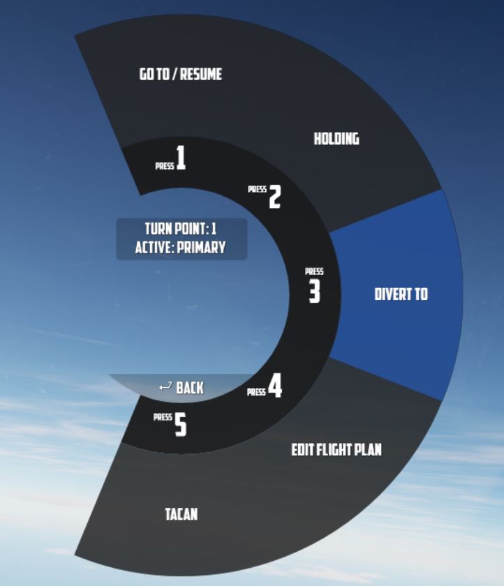
Pause & Resume Route
An active flight plan is indicated by the UI using an asterisk * next to the
current turn point.
Automatic turn point switching can be temporarily disabled per turn point using
the Holding option. Turn points designated for holding are marked
with a h.
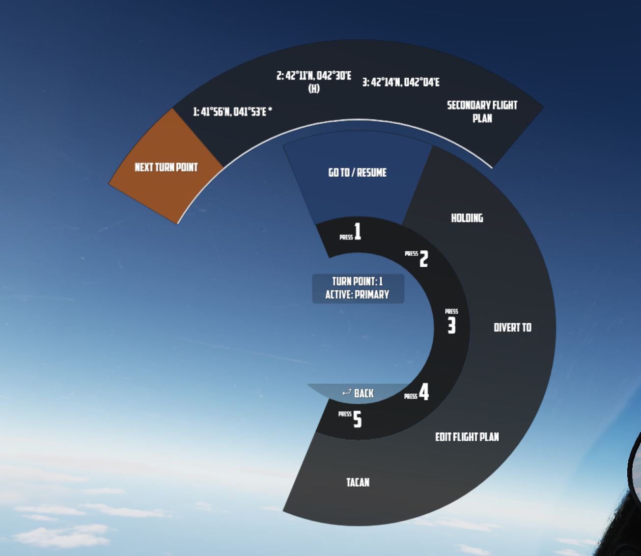
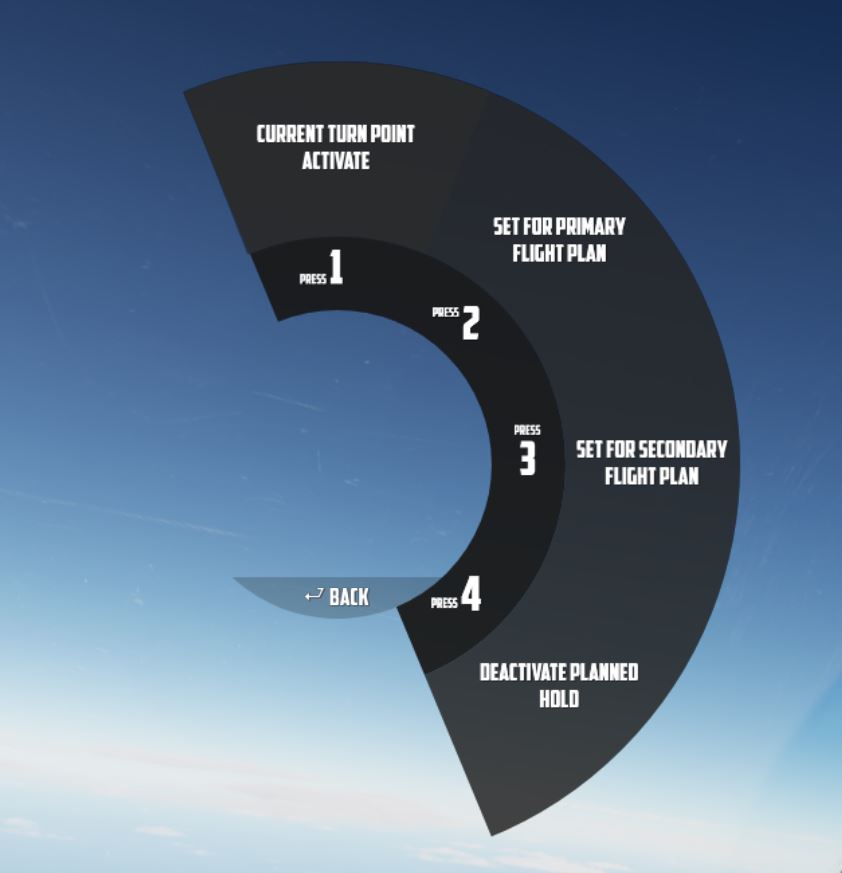
When a flight plan has been paused, for example, because the pilot diverted to a different point (using TGT 1), it can be reactivated through the UI again by using the Go To/Resume option.
This also offers the possibility to skip turn points by jumping directly to any turn point in its sequence, as well as returning to previous points or resuming from a point designated for holding.
TACAN
The TACAN equipment can be operated by both crew members independently and then swapped between Pilot and WSO by using the Command Button on the panel.
Further, Jester is able to tune directly to any TACAN capable asset or ground station.
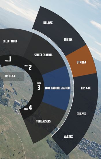
This also allows the pilot to set up Jesters TACAN panel with a secondary setup to then switch between both with a single click on the Command Button.
UHF
The UHF radio is duplicated between both crew members and can be operated independently. Using the Command Button allows the pilot to swap control between their and Jesters setup. This enables the pilot to setup two configurations and then swap between them fast with a single button press.
Jester is able to tune the radio directly to any nearby asset or ATC to enable and open a communication channel conveniently and quick. Via ADF, this can also be used for navigation.
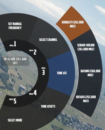
Combat
Jesters assistance for combat situations is generally divided into options on the Jester Wheel, whenever not in a high action environment yet, and a smart Context Action for use during situations that require acting quick, such as during a fight.
Context Action
The context command (by default V) allows for intuitive cooperation and exchange between Pilot and WSO based on the following contexts:
- Pave Spike - TGT FIND selected on the Delivery Mode Knob
- Dive Toss - DT or DL selected on the Delivery Mode Knob
- Dogfight - CAGE mode
- Beyond Visual Range - other
The context action can change semantics if pressed only momentarily, if hold or if clicked twice (double-click).
| Context | Duration | Action |
|---|---|---|
| BVR - Scan | • | Select next target |
| ▄ | Lock selected target | |
| •• | Reset target selection | |
| BVR - Lock | •, ▄ | Drop lock, but keep target in focus |
| •• | Drop lock and focus | |
| Dogfight | •, ▄ | Lock/Unlock contact ahead |
| •• | Exit CAGE mode | |
| Dive Toss | Lock/Unlock ground return | |
| Pave Spike | Lock/Unlock target next to reticle |
Radar
During flight, Jester will constantly operate the radar and search for contacts.
In certain situations, such as during landing, on the ground or when performing
AAR, the radar will be in Standby mode. This can also be commanded manually by
selecting Radar > Operation > Go Cold in the UI.

When using the radar, Jester generally differentiates between two phases:
- Scan
- Lock
The phases are commanded and switched by the pilot using the Context Action.
Additionally, Jester will behave differently during a dogfight, indicated by the pilot entering CAGE mode.
Scan
This is the default phase Jester will be in. He will automatically point the antenna at different altitudes and ranges in order to scan the entire space ahead of the aircraft.
Jester will automatically identify any new contact and call them out to the pilot.
If desired, the player can request Jester to perform an IFF challenge manually at any time through the UI (this action can also be bound directly to a key). Should the situation require, the player can manually set a zone for Jester to scan outside of his regular pattern through the UI.
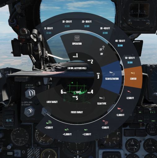
He will then scan this zone for a while first before proceeding back to his regular pattern.
Likewise, the display range and scan type (wide or narrow) to be used during scanning can be selected as well.
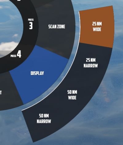
Target Selection
Whenever a bandit becomes a threat (closer than 25 nm), Jester automatically selects the target by moving and keeping the cursor on the corresponding radar return.
The player can command target selection at any time by using the context actions. This way, targets outside of the threat-range can be selected as well.

Whenever a target within threat-range is selected, Jester will focus them, stop the regular search pattern, automatically enter Narrow View and point the antenna at the target in order to maximize tracking quality.
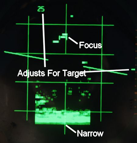
This mode can be understood as "Track While Scan", where Jester keeps the radar on a specific contact, while still scanning the surrounding space, identifying and calling out any new contact spotted.
Context actions only allow selection of hostile aircraft. Should the situation require, other targets can always be focused directly through the UI instead.
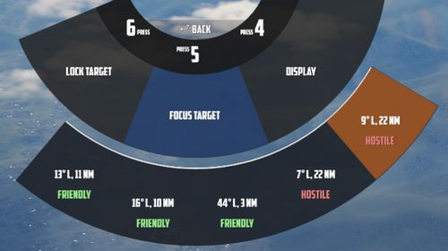
Automatic target selection and focus behavior can be deactivated in the UI. This can be useful if flying through a hostile zone, expecting contacts, while not wanting to engage them and instead keep an overview and continuing the scan pattern. For example when having an escort of fighters that will take care of the bandits instead.
Context Action
| Duration | Context Action |
|---|---|
| • | Select next target |
| ▄ | Lock the currently selected target |
| •• | Reset target selection |
Unless only a single bandit shows on the screen, locking via ▄ (long) requires prior target selection. Either automatically through Jester or by using • (short). In an ambiguous situation, pressing ▄ (long) will first select the target with highest priority.
Pressing •• (double) will reset the currently selected target and return Jester to his standard behavior of automatically selecting the highest threat, if any. Should one desire to ignore a target within threat range, automatic target focus has to be deactivated through the UI first. •• (double) can then be pressed to deselect the target.
Lock
During a lock, Jester works the radar to keep the lock as long as possible.
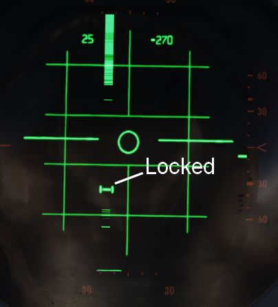
The UI also allows selecting a target to lock manually without using context action.
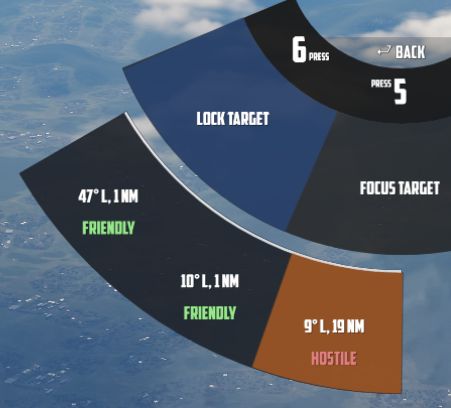
If a contact should drop while Jester attempts to lock it, he will wait a few seconds for the radar return to reappear.
| Duration | Context Action |
|---|---|
| •, ▄ | Drop lock, but keep target in focus |
| •• | Drop lock and focus |
💡 Should a lock be faulty and Jester does not notice it (for example odd movement of the steering dot, or unexpected closure rate readouts), press ▄ to unlock and then ▄ again to attempt to lock the target again.
Dogfight
A within-visual-range situation is entered by the pilot activating CAGE mode.
In this mode, the radar is automatically boresighted forward and Jester will be able to lock a return.
Further, the pilot can enter CAA mode where the system will automatically lock any close contact.
| Duration | Context Action |
|---|---|
| •, ▄ | Lock or Unlock contact ahead |
| •• | Exit CAGE mode |
To lock a target in CAGE mode, press • (short) or ▄ (long) once ready. Jester will now automatically lock the first target return he can identify. If no target could be found within a few seconds, Jester will abort the process and • or ▄ have to be used again.
💡 Targets have to be within 5 degrees of the boresight or a lock attempt would result in a bad lock. When Jester does not lock the return yet, it is because he is waiting for the pilot to put it within that zone first.
LANTIRN
Bombing
🚧 This section is under construction
Dropping ordnance on ground targets with Jester consists of two phases. Initially, Jester has to prepare for the attack by entering corresponding data into the panels. For most modes, the attack run itself can be executed by the pilot alone. However, for Dive Toss and Dive Laydown modes, Jester must lock the ground return using the radar.
Preparation
To prepare a bombing run, both pilot and WSO have to enter several settings throughout the cockpit.
For Jester, this includes the WRCS panel, such as the Release Range, Target Altitude or Release Advance, as well as the LABS angles and timers.
To prepare Jester for a bombing run, use the Bombing Computer tool and transfer the solution by utilizing the Tell Jester button.
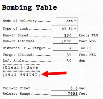
Once activated, Jester will do his part in preparing the aircraft for the desired attack.
Dive Toss
During a Dive Toss or Dive Laydown attack, indicated by DT or DL selected on the Delivery Mode Knob, the Context Action can be used to command Jester to lock the ground return after placing the nose on the target. A subsequent press will unlock the target again.
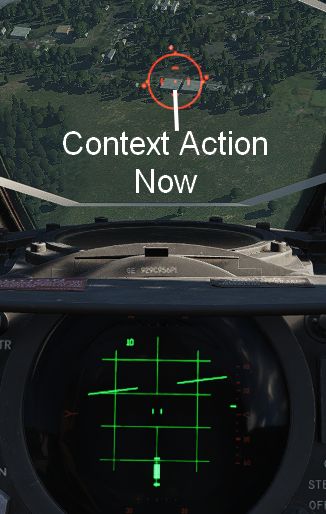
This way, ground targets can be attacked effectively during a dive. The pilot places the reticle on the target, commands Jester to lock the return and then pulls up while holding down the Bomb Button. Weapons will be released automatically shortly after.
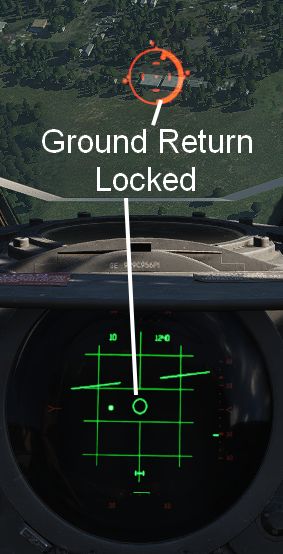
Other
🚧 This section is under construction
During the entire flight, Jester will assist the pilot in all situations.
He will call out bandits during a dogfight and give the pilot steering tips. Jester might tell the pilot in which direction to evade when attacked by a missile, make him aware of any friendly traffic spotted or also simply when the AVTR cassette is full.
While lacking a fuel gauge in his cockpit, he will observe the clock and the pilots flying style to remind him about checking the fuel level or consumption when forgetting to leave the Fuel Dump switch activated.
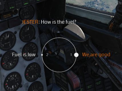
Jester is able to assess and report battle damage to a certain degree and much more.
Iceman

In addition to Jester, or rather, as a subset of the Jester AI, the Heatblur DCS F-14 also has Iceman, a basic autopilot/AI. This is intended for use in single-player where a player might jump between the front and back seats to control both positions and enables a basic autopilot controllable from the back seat using the same methodology as the Jester controls from the front seat.
The basic functionality is that when the player switches to the RIO seat, Iceman takes control of the current heading and altitude. The, now Iceman, menu then allows the player to set heading, altitude, and speed. Heading and altitude can be set relative to a target or as absolutes not referencing an external target.
Assisted Startup

For aircraft cold start, Jester can either perform his checklist like a real RIO would, or he can also help the pilot with an assisted startup in which he reads the pilot’s checklist to him while starting.
To access the normal, unassisted startup, select startup, Jester will then go through his checklist. He will at times ask the pilot if he has completed certain checks or ask for specific tests; this is answered via the Jester menu using the options appearing there. For example, he will start by asking for a comms check, which is answered via the Jester menu. Note that after engine startup and EMERG GEN Master test, he will ask for what INS alignment to go for, select this via the Jester menu as well.
To access the assisted startup, select assisted start on the Jester menu. Jester will now read out the checklist to the pilot and highlight the relevant indicators and switches during startup. Use the Jester menu to tell Jester when a check/step is complete.
Takeoff and Landing Assistance
When taking off, Jester will report key values for the airspeed, indicating to the pilot when to initiate the roll.
By default, Jester will assist the player during landing by giving altitude callouts, similar as seen in civilian aviation. This way, the pilot can better estimate the current position, especially given the reduced forward visibility in the Phantom.
💡 This option can be disabled, see 9.2. Special Options.
Aerial Refueling
Jester provides steering assistance to the pilot during AAR.
Normal Procedures
This chapter contains standard procedures for operating the F-4E Phantom II.
The aircrew procedures through the Before Taxi paragraph are separated into individual procedures for the pilot and weapon system officer. These separate procedures allow the individual crew-member to perform the checks without requiring him to read the checks performed by the other crew-member. The remaining procedures are combined and are coded for applicable crew-member action. Items coded (P-RIO) are applicable to both the pilot and weapon system officer. Items coded (RIO) are applicable to the weapon system officer only, and items not coded are applicable to the pilot only.
💡 Real procedures and checklists evolved over time. The procedures provided in this manual are based on a time range around the 80s and tailored to our simulation of the Phantom specifically. Procedures provided in other resources may differ slightly.
See the Definitions for an explanation of the symbology used.
🚧 This section is under construction
Preparation for Flight and Interior Inspection
💡 If a battery start is to be made, those checks requiring electrical power will have to be performed after the engines have been started.
WSO
Before Electrical Power (WSO)
| Step | System | Action |
|---|---|---|
| 1. | Helmet | PUT ON |
| 2. | AN/ALE-40 Chaff Dispenser | OFF |
| 3. | Throttles | AFT |
| 4. | UHF radio | OFF |
| 5. | AVTR Switch | OFF |
| 6. | Radar power | OFF |
| 7. | DSCG | OFF |
| 8. | ECM equipment | OFF |
| 9. | INS | OFF |
| 10. | Nuclear store consent switch | SAFE |
| 11. | Nav computer | OFF |
| 12. | Battery bypass switch | OFF |
| 13. | Circuit breaker panels | CHECK |
| 14. | Publications and flight data | CHECK |
After electrical power (WSO)
| Step | System | Action |
|---|---|---|
| 1. | Instrument ground power switch | ACTUATE⚡ |
| 2. | Navigation Computer | SET |
| a. NAV Comp Mode | STBY | |
| b. Wind Counters | SET | |
| c. Variation Counter | SET | |
| d. POS Update Switch | NORM | |
| e. Present POS Counter | SET | |
| f. Target Counters | SET FOR TGT 2 | |
| g. NAV Comp Mode | RESET | |
| h. NAV Comp Mode | STBY | |
| i. Target Counters | SET FOR TGT 1 | |
| 3. | INS Alignment | AS DESIRED |
💡 To avoid electrical power interruption which could result in an INS NO-GO indication, ensure INS is not in the ALIGN mode when the generator switches are placed to ON. If a power interruption does occur, switch the power control knob to OFF. When power is restored, go from OFF to ALIGN pausing momentarily at STBY.
INS Full Gyrocompass Alignment (WSO)
Time depends on ambient temperature and BATH alignment accuracy.
| Step | System | Action |
|---|---|---|
| 1. | NAV Comp Mode | STBY |
| 2. | INS Power Knob | STBY |
| 3. | Gyro Heat Up | WAIT |
| a. HEAT Light | OUT | |
| 4. | INS Power Knob | ALIGN |
| 5. | Alignment | WAIT |
| a. ALIGN Light | FLASHING | |
| 6. | INS Power Knob | NAV |
| 7. | INS Light | OUT |
INS Fast BATH Alignment (WSO)
Takes roughly 2 minutes 15 seconds.
| Step | System | Action |
|---|---|---|
| 1. | NAV Comp Mode | STBY |
| 3. | INS Power Knob | STBY |
| 4. | INS Power Knob | ALIGN |
| 5. | Alignment | WAIT |
| a. HEAT Light | IGNORE | |
| b. ALIGN Light | STEADY | |
| 6. | INS Power Knob | NAV |
| 7. | INS Light | OUT |
INS Stored Heading Alignment (WSO)
Takes roughly 2 minutes 15 seconds.
| Step | System | Action |
|---|---|---|
| 1. | NAV Comp Mode | STBY |
| 2. | Align Mode Switch | HDG MEM |
| 3. | INS Power Knob | ALIGN |
| 4. | Alignment | WAIT |
| a. HEAT Light | IGNORE | |
| b. ALIGN Light | FLASHING | |
| 5. | INS Power Knob | NAV |
| 6. | INS Light | OUT |
| 7. | Align Mode Switch | GYRO COMP |
Interior Check (WSO)
| Step | System | Action |
|---|---|---|
| 1. | Rudder pedals | ADJUST |
| 2. | Ejection seat height | ADJUST |
| 3. | Stick grip and boot | CHECK |
| 4. | Communication-Navigation control panel | SET |
| a. Communication frequency control knobs | AS REQUIRED | |
| b. Communication channel control knob | AS REQUIRED | |
| c. Mode select switch | AS REQUIRED | |
| d. Communication Volume control knob | AS DESIRED | |
| e. Auxiliary channel control knob | AS REQUIRED | |
| f. Auxiliary volume control knob | AS DESIRED | |
| g. COMM-AUX Pushbutton | TR + G - ADF | |
| h. Navigation volume control knobs | AS REQUIRED | |
| i. TACAN function selector knob | OFF | |
| j. Communication command button | AS DESIRED | |
| k. Navigation command button | AS DESIRED | |
| 5. | VOR/ILS/marker beacon volume | AS DESIRED |
| 6. | Emergency slats flaps handle | FORWARD |
| 7. | Intercom control panel | SET |
| a. Volume control | AS DESIRED | |
| b. Amplifier select knob | NORM | |
| c. Function selector switch | HOT MIC | |
| 8. | Emergency gear handle | IN AND SECURE |
| 9. | Emergency brake handle | IN AND SECURE |
| 10. | Slats flaps position indicators | GEAR DOWN INDICATION |
| 11. | Canopy emergency jettison handle | FORWARD |
| 12. | Radar scope | SECURE |
| 13. | Attitude indicator | CHECK AND SET⚡ |
| a. Rotate pitch trim knob to check travel (-10° to +5°) | ||
| b. Set horizon bar level with miniature aircraft | ||
| 14. | Clock | WIND AND SET |
| 15. | Accelerometer | SET |
| 16. | Navigation function selector switch | AS DESIRED |
| 17. | Digital display indicator lamp button | PRESS |
| 18. | Navigational computer set control lamp button | PRESS |
| 19. | KY-28 power selector knob | OFF |
| 20. | KY-28 mode selector | P |
| 21. | Canopy manual unlock handle | FORWARD |
| 22. | Aural tone | AS REQUIRED |
| 23. | Cockpit lights control knob | AS REQUIRED |
| a. White floodlight switch | OFF | |
| b. Instrument panel lights control knob | AS REQUIRED | |
| c. Console lights control knob | AS REQUIRED | |
| d. Standby compass light switch | AS REQUIRED | |
| e. Console floodlight switch | AS REQUIRED | |
| f. Indexer lights control knob | AS REQUIRED | |
| 24. | Warning and indicator lights | TEST⚡ |
| 25. | Intercom system | CHECK |
| 26. | Oxygen quantity gage | CHECK⚡ |
| Check quantity sufficient and OFF flag not visible. | ||
| 27. | Oxygen supply system | CHECK AND SET |
Pilot
Before Interior Inspection (Pilot)
| Step | System | Action |
|---|---|---|
| 1. | Helmet | PUT ON |
| 2. | Lower ejection handle guard | UP (not applicable) |
| 3. | Generator switches | OFF |
| 4. | AN/ALE-40 flare select switch | NORMAL |
| 5. | Internal wing dump switch | NORM |
| 6. | Throttles | OFF |
| 7. | External stores emergency release | CHECK NO YELLOW SHOWING INSIDE CIRCULAR GUARD |
| 8. | Landing gear handle | IN & DOWN |
| 9. | Missile jettison selector | OFF |
| 10. | Armament Switches | OFF/SAFE |
| 11. | Pitot Heat | OFF |
| 12. | Battery | CHECK |
| To determine battery relay closure turn on Engine Master switch and check for proper positioning of gear and slats flaps position indicators. | ||
| 13. | Engine Master Switches | OFF |
| 14. | Formation Lights | OFF |
| 15. | Emergency attitude reference system circuit breaker | IN |
| 16. | UHF Radio | OFF |
| 17. | Reference system selector | STBY |
| 18. | Publications and flight data | CHECK |
| 19. | Gun Camera magazine | INSTALL |
| 20. | Gun Camera dust cover | STOW (with 780 equipment) |
| 21. | External Power | ON🔧 AND CHECK ON |
| 22. | Generator switches | EXT ON |
| 23. | Transformer-rectifier | CHECK ⚡ |
| Both transformer-rectifiers operating if the landing gear indicators indicate gear down with the Engine master switches OFF and the generator switches in EXT. |
Interior Inspection (Pilot)
| Step | System | Action |
|---|---|---|
| 1. | Rudder Pedals | ADJUST |
| 2. | Ejection Seat Height | ADJUST ⚡ |
| 3. | Stick grip and boot | CHECK |
| Check Stick grip firmly attached to stick and stick boot in place with no tears | ||
| 4. | Auxiliary armament control panel | SET |
| a. Gyro Switch | NORM | |
| b. Aural tone control knob | LOW | |
| c. Boarding Steps position indicator | PROTRUDING | |
| 5. | Slats override switch | NORM |
| 6. | Intercom control panel | SET |
| a. Volume control | AS DESIRED | |
| b. Amplifier select knob | NORM | |
| c. Function selector switch | HOT MIC | |
| 7. | ALE-40 flares switch | NORMAL |
| 8. | Fuel control panel | SET |
| a. Internal wing transfer switch | NORMAL | |
| b. Internal wing dump switch | NORM | |
| c. Refuel select switch | ALL TANKS | |
| d. External transfer switch | AS REQUIRED | |
| e. Air refuel switch | RETRACT | |
| 9. | Stab Aug Switches | OFF |
| 10. | Boost Pumps | CHECK⚡ |
| Actuate left boost pump check switch observe that the left boost pump pressure indicator reads 30 ±5 PSI. Allow 3 seconds after release of the left switch, then repeat with right boost pump. Ensure that the test switches return to NORMAL | ||
| 11. | VOR/ILS Panel | SET |
| a. Volume control knob | AS DESIRED | |
| b. Marker volume knob | AS DESIRED | |
| c. Frequency | AS DESIRED | |
| d. VOR/MKR test switch | TEST⚡ | |
| 12. | Slats/Flaps switch | AS REQUIRED |
| Slats/Flaps switch should correspond with indicators | ||
| 13. | Emergency Slats/Flaps handle | FORWARD |
| 14. | Drag Chute control handle | DOWN AND SECURE |
| 15. | Speed brake switch | IN |
| 16. | Throttle friction lever | SET DESIRED |
| 17. | Comm Antenna Select Switch | UPR |
| Anti-skid and Nose wheel steering may malfunction while transmitting on the lower antenna due to electromagnetic interference. | ||
| 18. | Engine Anti-icing switch | NORMAL |
| 19. | Anti-Skid | CHECK⚡ |
| a. Anti-Skid switch on | LIGHT OFF | |
| b. Emergency quick release lever | DEPRESS/LIGHT ON AND RELEASE LIGHT OFF | |
| c. Anti-Skid Switch off | LIGHT ON | |
| 20. | ARI circuit breaker | IN |
| 21. | Landing and taxi lights switch | OFF |
| 22. | Slats flaps position indicator | SELECTED POSITION |
| 23. | Landing gear position indicators | GEAR DOWN INDICATION |
| 24. | Emergency brake control handle | IN AND SECURE |
| 25. | Canopy emergency jettison handle | FORWARD |
| 26. | Multiple weapons control panel | SET |
| a. Master Arm Switch | SAFE | |
| b. Delivery mode knob | OFF | |
| c. Weapon select knob | C | |
| d. Radar missile power switch | OFF | |
| e. Selective jettison knob | OFF | |
| f. Interlock switch | IN | |
| g. CL TK Light | ON IF CENTERLINE TANK IS INSTALLED | |
| 27. | Accelerometer | SET |
| 28. | Flight Instrument Light Control | AS REQUIRED |
| 29. | Clock | WIND AND SET |
| 30. | Optical sight reticle | CHECK |
| 31. | Film magazine/dust cover | SECURE |
| 32. | ADI | CHECK AND SET⚡ |
| a. Rotate pitch trim knob to check travel (-10° +5° minimum) | ||
| b. Set horizon bar level with miniature Aircraft | ||
| 33. | Emergency attitude Indicator | CHECK |
| a. Cage and do not lock | ||
| b. Set miniature aircraft level with horizon bar | ||
| 34. | Navigation function selector panel | SET |
| a. Bearing distance selector switch | AS DESIRED | |
| b. Mode selector knob | AS DESIRED | |
| 35. | Fire warning lights | TEST |
| 36. | Canopy manual unlock handle | FORWARD |
| 37. | Arresting hook handle | UP |
| 38. | Communication-Navigation control panel | SET |
| a. Communication frequency control knobs | AS REQUIRED | |
| b. Communication channel control knob | AS REQUIRED | |
| c. Mode select switch | AS REQUIRED | |
| d. Communication Volume control knob | AS DESIRED | |
| e. Auxiliary channel control knob | AS REQUIRED | |
| f. Auxiliary volume control knob | AS DESIRED | |
| g. COMM-AUX Pushbutton | TR + G - ADF | |
| h. Navigation volume control knobs | AS REQUIRED | |
| i. TACAN function selector knob | OFF | |
| j. Communication command button | AS DESIRED | |
| k. Navigation command button | AS DESIRED | |
| 38. | Emergency vent knob | IN |
| 40. | Rain removal switch | OFF |
| 41. | Pitot heat | CHECK ⚡ 🔧 |
| 42. | Defog-footheat control handle | AS DESIRED |
| 43. | IFF Mode IV function switch | AS DESIRED |
| 44. | IFF Master control knob | OFF |
| 45. | Circuit breakers | CHECK |
| 46. | Temperature control panel | |
| a. Temperature control knob | AS DESIRED | |
| b. Mode selector switch | AUTO | |
| 47. | DCU-94/A bomb control monitor panel | SET |
| a. Station selector switches | AFT | |
| b. Master release lock switch | AFT | |
| c. Option selector knob | OFF | |
| 48. | Cockpit lights control knob | AS REQUIRED |
| a. White floodlight switch | OFF | |
| b. Instrument panel lights control knob | AS REQUIRED | |
| c. Console lights control knob | AS REQUIRED | |
| d. Standby compass light switch | AS REQUIRED | |
| e. Console floodlight switch | AS REQUIRED | |
| f. Indexer lights control knob | AS REQUIRED | |
| 49. | Warning and Indicator lights | TEST⚡ |
| 50. | Instrument flood lights | OFF |
| 51. | Aural stall warning volume | AS DESIRED |
| 52. | Compass control panel | |
| a. Latitude compensator | SET | |
| b. Mode control knob | SLAVED | |
| c. Synchronization indicator | CHECK | |
| 53. | Exterior lights control panel | SET |
| a. Fuselage lights switch | AS REQUIRED | |
| b. Wing lights switch | AS REQUIRED | |
| c. Tail lights switch | AS REQUIRED | |
| d. Exterior lights flasher switch | AS REQUIRED | |
| e. Formation lights control knob | AS REQUIRED | |
| 54. | Instrument lights intensity control panel | SET |
| 55. | Intercom System | CHECK |
| 56. | Oxygen quantity gage | CHECK (Cannot be done with battery start) |
| Check quantity sufficient, OFF flag not visible, OXYGEN LOW light extinguished. Press oxygen test button and check OXYGEN LOW light and MASTER CAUTION light illuminate at 1 litre. Notify rear crewmember, if applicable that test is in progress. | ||
| 57. | Oxygen supply system | CHECK AND SET |
Startup
Before starting engines (Both)
| Step | System | Action |
|---|---|---|
| 1. | Seat pins | CHECK REMOVED AND STOWED |
| 2. | Fore and Aft Area | CLEAR |
| 3. | Fire Guard | POSTED |
| 4. | Throttles | OFF |
Starting engines (Pilot)
| Step | System | Action |
|---|---|---|
| 1. | External Air source | CONNECT RIGHT🔧 |
| 2. | Engine Master Switches | ON |
| 3. | External airflow | ON🔧 |
| 4. | At 10% RPM | |
| a. Right Ignition Button | PRESS AND HOLD | |
| b. Right Throttle | HALF THEN IDLE | |
| 5. | At Lightoff (EGT INCR) | |
| a. Right Ignition Button | RELEASE | |
| 6. | At 45% RPM | |
| a. External airflow | STOP🔧 | |
| 7. | Check Parameters | |
| a. Exhaust Gas Temperature | 220 - 420 °C | |
| b. Fuel Flow Indicator | 800 - 1400 pph | |
| c. Idle RPM | 65 ± 1% | |
| d. Right Boost Pump | 30 ± 5 PSI | |
| e. Oil Pressure | 12 - 50 PSI | |
| f. Hydraulic Pressure | WITHIN LIMITS | |
| 8. | Right Generator | ON |
| 9. | Spoiler Actuator | CHECK (LEFT)🔧 |
| 10. | Air Refueling door | CHECK🔧 (if required) |
| 11. | Left Engine | START PER STEPS 1-8 |
| 12. | Right Generator | CYCLE OFF/ON |
| 13. | Bus Tie Open Light | OUT |
| 14. | External Air | DISCONNECT🔧 |
| 15. | External Power | DISCONNECT🔧 |
| 16. | Interior Check | COMPLETE |
Taxi
Before Taxi
Pilot
| Step | System | Action |
|---|---|---|
| 1. | COMM & NAV Equipment | ON & CHECK |
| 2. | IFF | STANDBY |
| 3. | Radar Altimeter | ON & CHECK |
| 4. | Altimeter & SPC | SET & CHECK |
| 5. | Speed Brakes | CHECK🔧 |
| 6. | Slats & Flaps | CHECK🔧 |
| 7. | Flight Controls | CHECK🔧 |
| 8. | Slats & Flaps | NORM |
| 9. | ARI Disengage | CHECK🔧 |
| 10. | STAB AUG Switches | ENGAGE AND CHECK🔧 |
| 11. | Reference Sys Select | PRIM (INS in NAV) |
| 12. | Compass Mode Control Knob | SYNC |
| 13. | AFCS | CHECK (if required) |
| 14. | STAB AUG Switches | DISENGAGE |
| 15. | Trim | CHECK🔧 & SET |
| 1-3 UNITS NOSE DOWN | ||
| 16. | Slats & flaps | OUT & DOWN🔧 |
| 17. | Optical Sight | STBY/CAGE |
| 18. | Pneumatic Pressure | CHECK |
| 19. | IFF | CHECK |
| 20. | Radar Altimeter | CHECK & SET |
| 21. | Wheel chocks | REMOVE🔧 |
🟡 CAUTION: Do not move aircraft with INS in ALIGN mode.
WSO
| Step | System | Action |
|---|---|---|
| 1. | Interior Check | COMPLETE |
| 2. | COMM & NAV Equipment | ON & CHECK |
| 3. | Target Designator | POWER ON & STOWED |
| 4. | Radar BIT Checks | INITIATE |
| 5. | WRCS BIT Checks | INITIATE |
| 6. | NAV Computer Mode | AS DESIRED |
| 7. | Altimeter & SPC | SET & CHECK |
Taxiing
| Step | System | Action |
|---|---|---|
| 1. | Wheel Brakes | TEST |
| 2. | Nose Gear Steering | ENGAGE & CHECK |
| 3. | (P-WSO) Flight Instruments | CHECK |
| 4. | (P-WSO) Oxygen Diluter | AS REQUIRED |
🟡 CAUTION: Taxi with canopies full open or full closed; with the canopies open, maintain taxi speeds below 60 knots to prevent damage to the canopy operating mechanism.
🟡 CAUTION: Adequate distance between aircraft must be maintained during formation taxi. An open canopy may be damaged by engine exhaust blast.
🟡 CAUTION: While taxiing during high gross weight conditions, the turning radius should be increased to relieve excessive side loads on the main landing gear struts, wheels, and tires.
Takeoff
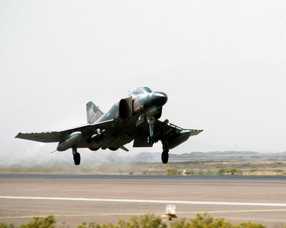 A right front view of an F-4 Phantom II aircraft taking off
from Shiraz Air Base during exercise Cento
A right front view of an F-4 Phantom II aircraft taking off
from Shiraz Air Base during exercise Cento
Normal Takeoff
The slats out-flaps down position is recommended for all takeoffs. After line-up on the runway and completing necessary pre-takeoff checks, engines can be run to 85% with brakes held and nose gear steering engaged to ensure nose gear alignment. With both engines operating in excess of 85% and the brakes locked, there is a possibility of rotating the tires on the wheel rims or skidding the tires. Check for normal rpm response and approximate readings of 450°C EGT, 4000 pph fuel flow, ¼ nozzles, and 30-40 psi oil pressure. After releasing brakes, advance both throttles rapidly to full military power and check rpm, exhaust temperatures and nozzle position. WSO check the ramps fully retracted. If an afterburner takeoff is desired, shift the throttles into the afterburner detent and advance full forward for max thrust. Maintain directional control with nose gear steering or rudder as required. The rudder becomes effective for steering at approximately 70 knots. Wheel braking should not be used for directional control during takeoff roll. Nose gear steering should be disengaged when rudder steering becomes effective. If it becomes necessary to re-engage nose gear steering at the higher speeds, rudder pedals should be returned to neutral prior to engagement since rudder displacement necessary for rudder steering will generally be excessive for nose gear steering. Sufficient aft stick should be applied prior to nose wheel liftoff speed to attain the desired pitch attitude. As the nose rises, pitch attitude must be controlled to maintain a 10° to 12° (first pitch mark) nose high attitude for aircraft fly-off. Caution must be exercised to preclude over-rotation due to excessive aft stick rate or an extended takeoff roll due to late lift-off. The basic takeoff attitude should be held during acceleration and transition to a clean configuration. Trim change and control action during this period are normal. The AUX AIR DOORS, WHEELS, and MASTER CAUTION lights may illuminate momentarily as the landing gear and flaps are retracted.
🟡 CAUTION: Rapid full aft movement of the stick between takeoff airspeed and 30 knots below takeoff airspeed may result in the stabilator hitting the runway with the possibility of stabilator actuator damage.
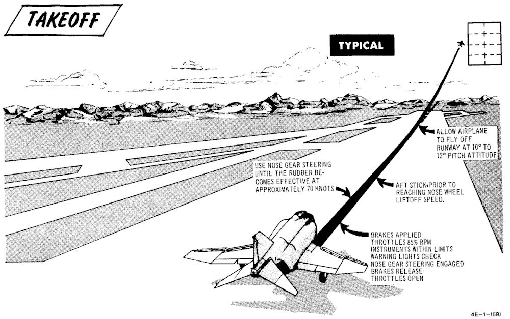
No-Flap Takeoff
No-flap takeoffs are not recommended. However, if it is determined that no-flap takeoffs must be performed to satisfy mission requirements, aircrews should be aware that takeoff roll and airspeed will be increased and: the takeoff attitude will be slightly steeper. Stabilator effectiveness is considerably increased and extreme caution must be exercised to prevent over-rotation which could result in the stabilator striking the runway.
🔴 WARNING: Due to increased stabilator authority with the flaps up, aircraft rotation can be initiated at lower than normal airspeeds and over-rotation is a definite possibility. If it appears that over-rotation is occurring, positive control movement (stick forward) must be taken to prevent the stabilator from contacting the runway and/or loss of aircraft control.
Minimum Run / Heavy Gross Weight Takeoff
A minimum run/heavy gross weight takeoff (aircraft over 55,500 pounds) is accomplished in the same manner as a normal takeoff with the following exceptions: It is recommended that all minimum run/heavy gross weight takeoffs be made with afterburner. During the takeoff-run, full aft stick must be applied prior to reaching 80 knots. As the aircraft starts to rotate, the stick should be adjusted to maintain 10° to 12° pitch attitude for aircraft fly-off. The possibility of a main landing gear tire failure increases with an extended takeoff ground run under heavy gross weight conditions. Nose wheel liftoff speed and takeoff speed is increased during heavy gross weight conditions. In the event of an aborted takeoff, it must be remembered that stopping distance is greatly increased as abort speed increases.
🟡 CAUTION: With a combination of light gross weight and aft CG, the minimum run takeoff technique (i.e., full aft stick prior to reaching 80 knots) produces rapid pitch rates during nose rotation. This combination can exist when the radar package and nose gun (or equivalent ballast) are not installed.
Crosswind Takeoff
Under crosswind conditions, the aircraft tends to weather vane into the wind. The weathervaning tendency can be easily controlled with nose gear steering. As forward speed increases, weathervaning tendency decreases. At speeds above 70 knots rudder effectiveness will normally be sufficient to maintain directional control. After the nose is lifted to takeoff attitude, the aircraft will have a tendency to drift toward the downwind side of the runway. Therefore, when a long time period is expected between nose lift-off and aircraft fly-off, or when the crosswind effect is particularly severe, nose lift-off can be delayed accordingly. Under normal operational conditions this action should not be required. As the aircraft leaves the ground, it should be crabbed into the wind, wings level, to maintain runway alignment. Takeoff in gusty crosswind or severe wake turbulence conditions can result in an abrupt wing low attitude at or near lift-off. When these conditions are anticipated, use higher than computed takeoff speed to provide additional lateral control after lift-off.
After Takeoff
When the aircraft is definitely airborne:
Retract the gear. Check that the landing gear position indicators display the word UP, and that the landing gear handle warning light is out.
🟡 CAUTION: The landing gear and gear doors should be completely up and locked before the gear limit airspeed of 250 knots is reached, otherwise, excessive air loads may damage the landing gear mechanism and prevent subsequent operation.
Set slats and flaps to NORM. Check that slat flap indicators display IN and UP. Rudder jumps may occur during flap retraction with a lateral stick input. If an audible (noticeable in head phones) chattering associated with slat flap and utility hydraulic pressure indicator fluctuating in unison occurs during slats flaps retraction, maintain airspeed below 250 knots and cycle slats flaps. If slat chatter occurs during maneuvering at altitude, it may require opposite slats positioning from where chatter occurs. If chatter persists, extend slats flaps and land as soon as practical. If cycling (slats repositioning) eliminates chatter, continue mission and make an appropriate entry in AF Form 781.
Climb
A simplified climb can be made by maintaining a 10° to 12° (first pitch mark) nose high attitude until reaching 350 knots and then vary pitch as necessary to maintain 350 knots until reaching cruise Mach/TAS. Vary pitch as necessary to maintain cruise Mach/TAS until reaching cruise altitude. A simplified Maximum thrust climb, at normal gross weights, can be made by maintaining a 10° to 12° nose high attitude until reaching 350 knots and then vary pitch as necessary to maintain 350 knots until reaching Mach 0.9. Vary the pitch attitude as necessary to maintain Mach 0.9 until reaching cruise altitude.
💡 During the climb, it may be necessary to place the antenna selector switch to the LWR position to maintain ground communication.
Rig Check
A rig check shall be performed if an out-of-rig or unintentional asymmetric load condition is suspected and before maximum-performance/high-AOA maneuvering. With all axes of the stab aug engaged, center the rear cockpit ball and check that aircraft does not roll more than 2°/second with ailerons and spoilers trimmed neutral. Ifa large amount of lateral trim (equivalent to more than 1 inch aileron down at 350 knots) is required to prevent roll, an out-of-rig, malfunctioning stab aug, or asymmetrical load condition exists. Do not maneuver at high angle of attack if this condition exists.
Stab Aug Check
A stab aug check shall be performed before maximum-performance/high-AOA maneuvering. Do not perform maximum performance maneuvers if any of the following checks are unsatisfactory.
- Pull nose up with 2G acceleration and release the stick. Aircraft should stabilize in one cycle.
- Yaw aircraft to one ball width and release rudder. Aircraft should stabilize in one cycle.
- Roll to 30-45° bank and release stick. Aircraft should maintain bank angle. Roll to level flight and release stick. Aircraft should maintain wings level.
- Gradually increase AOA through 11 1/2 units and ensure slats extend together. Decrease AOA below 10 1/2 units and ensure slats retract together.
Takeoff Checklists
Before Takeoff (Pilot)
| Step | System | Action |
|---|---|---|
| 1. | Optical Sight | CHECK |
| 2. | Internal Wing Transfer | NORMAL |
| 3. | STAB AUG Switches | ENGAGE |
| 4. | Flight Controls | UNRESTRICTED (WSO confirm) |
| 5. | Slats & Flaps | CHECK OUT & DOWN |
| 6. | Anti-Ice | AS REQUIRED |
| 7. | STAB Trim | CHECK 1-3 UNITS NOSE DOWN |
| 8. | Fuel Quantity | CHECK |
| 9. | (P-WSO) Canopies | CLOSE & CHECK (WSO then Pilot) |
| 10. | Warning Lights | TEST |
| 11. | Defog & Temperature | AS REQUIRED |
| 12. | (WSO) Command Selector | AS BRIEFED |
| 13. | (P-WSO) Ejection Seats | ARM (not applicable) |
After Runway Line-Up
| Step | System | Action |
|---|---|---|
| 1. | External Transfer | AS DESIRED |
| 2. | Anti Skid | ON & LIGHT OUT |
| 3. | Compass Heading | CHECK |
| 4. | Pitot Heat | ON |
| 5. | IFF | AS REQUIRED |
| 6. | (P-WSO) Circuit Breakers | CHECK IN |
| 7. | Warning Lights | CHECK |
Normal Takeoff
| Step | System | Action |
|---|---|---|
| 1. | Wheel Brakes | APPLY |
| 2. | Throttle | 85% RPM MAX |
| 3. | Engine gauges | CHECK |
| a. Exhaust gas temperature | 450°C | |
| b. Fuel flow | 4000 pph | |
| c. Nozzles | 1/4 | |
| d. Oil pressure | 30-40 psi | |
| 4. | Wheel brakes | RELEASE |
| 5. | Throttle | MIL |
| 6. | Engine gauges | CHECK |
| 7. | Throttle | AFTERBURNER (IF DESIRED) |
| 8. | Nose gear steering | DISENGAGE at 70 KNOTS |
| 9. | Stick | MOVE AFT at 80 KNOTS |
| 10. | Pitch attitude | MAINTAIN 10° to 12° |
| 11. | Trim | AS REQUIRED |
After Takeoff - Climb
| Step | System | Action |
|---|---|---|
| 1. | Gear | UP |
| 2. | Slats & Flaps | NORM (180 knots MIN) |
| 3. | Pitch | ADJUST 10°-12° TILL 350 KIAS |
| 4. | Airspeed | ADJUST PITCH TO HOLD 350 KIAS |
| 5. | Heading | ACCORDING TO FLIGHT PLAN |
Cruise
| Step | System | Action |
|---|---|---|
| 1. | (P-WSO) Altimeters | |
| SET | ||
| CHECK STBY | ||
| RESET | ||
| COMPARE | ||
| 2. | Radar Altimeter | AS REQUIRED |
| 3. | (WSO) Command Selector | AS BRIEFED |
| 4. | (P-WSO) Ops Check | |
| a. Oxygen Quantity/Pressure/Blinker | CHECK | |
| b. Cockpit Pressure | CHECK | |
| c. Fuel Quantity/Transfer Switches | CHECK | |
| d. STBY Compass | CHECK | |
| e. Circuit Breakers | CHECK | |
| 5. | Anti-Ice Switch | AS REQUIRED |
Landing
This chapter describes landing techniques.
 An AIRMAN retrieves a drag chute from a 70th Tactical Fighter Squadron
F-4E Phantom II aircraft at the end of a runway during Exercise PROUD PHANTOM'80
An AIRMAN retrieves a drag chute from a 70th Tactical Fighter Squadron
F-4E Phantom II aircraft at the end of a runway during Exercise PROUD PHANTOM'80
Visual Landing
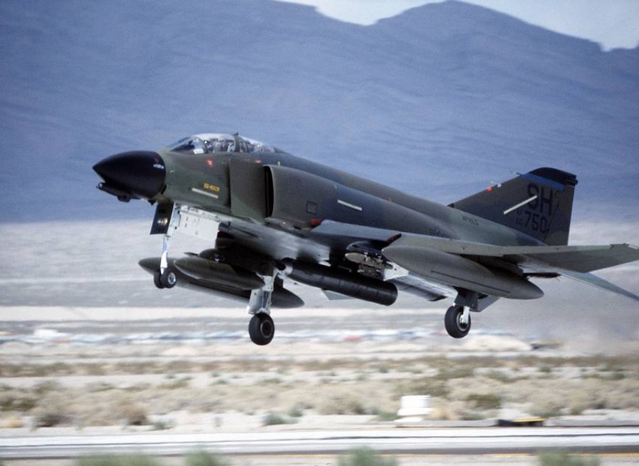 An Air Force Reserve F-4 Phantom II aircraft lands during Exercise GUNSMOKE '85
Descent / Before Landing
The Descent/Before Landing check should be accomplished above 10,000 feet AGL and at a time when mission/flight demands are not critical. Prior to performing a rapid descent, the windshield and canopy surfaces should be preheated to prevent the formation of frost or fog. If it becomes necessary to dump fuel during a descent, thrust settings in excess of 85% rpm may be required to ensure rapid inflight dumping.
💡 Due to limited forward visibility, it is advisable to raise the seat up before entering the pattern.
Landing Technique
For a normal landing, fly the pattern as illustrated in figure. Enter the pattern as local policy dictates.
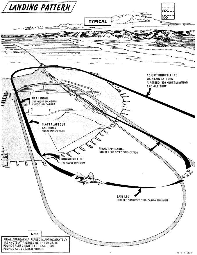
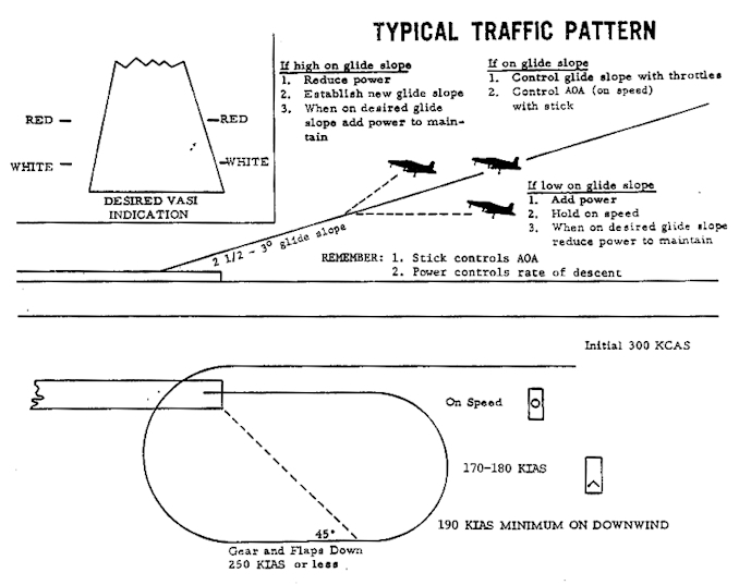
🔴 WARNING: If high angles of attack develop during the turn to downwind, the rudder should be used as a primary means of rollout since adverse yaw may be introduced by the use of ailerons. Altitude may be insufficient for recovery if uncontrolled flight is encountered.
Avoid buffet throughout the landing pattern. Adjust power, as necessary, to attain allowable gear lowering airspeed. Extend landing gear and slats and flaps in level flight on downwind. Actual flap extension may not occur until slowing to 210 knots. Ensure slats out-flaps down prior to initiating turn to base leg. The optimum indicated AOA for approach is 19.2 units, and is adequate for all gross weight and normal slat flap configurations. The AOA aural tone system provides an audible cue to maintain an on-speed approach (steady tone played at medium pitch). During very gusty flight conditions, full aileron may not be sufficient to correct a wing low condition. When landing in gusty or crosswind conditions, with wake turbulence, with high internal fuel load (aft CG), or with an abnormal configuration (slats in, asymmetric slats or slats partially extended), a 17 unit AOA approach is recommended. A transition to ON SPEED and a flared landing will reduce the touchdown speed. The AOA indexer and aural tone indications remain unaffected. Establish and maintain On Speed angle-of-attack on the base leg or final approach, adjusting pitch attitude to maintain AOA and power to maintain desired glide slope/rate of descent. Cross-check computed airspeed and On Speed AOA to detect gross errors in AOA. When the aircraft reaches 20 to 30 feet altitude above the ground, ground effect will tend to rotate the aircraft in the nose-down direction. Maintaining pitch attitude will result in transition to a slightly slow indication at touch-down which is desired. Flying a 2 1/2° to 3° glide slope will produce an approach rate of descent of about 700 feet per minute. Sink rate at touchdown will be appreciably reduced by ground effect.
🟡 CAUTION: Flying a steeper than normal final approach or not maintaining pitch attitude when entering ground effect, can cause touchdown sink rates to exceed the design limit of the main landing gear struts.
At touchdown, reduce power to idle and deploy drag chute. Use full aft stick to help decelerate. Use rudder and ailerons for directional control down to 70 knots then use differential braking. Nose gear steering should not be required for directional control in light crosswind conditions. However, if rudder, aileron, and/or differential braking are not effective in maintaining directional control, use nose gear steering as required. Engage nose gear steering only with the rudder at or near neutral.
🔴 WARNING: Nose gear steering malfunctions can cause loss of directional control if engaged at high ground speed; therefore, it should not be engaged above taxi speed unless required to maintain directional control during crosswind landing conditions. If no response is noted or unscheduled steering responses are detected when engaging nose gear steering, disengage immediately and do not reengage.
During braking, cycling of the anti-skid system can be detected by a change in longitudinal deceleration. Cycling may not be apparent when braking at high speed immediately after landing, with drag chute failure, or with a wet or icy runway. Do not misinterpret this as anti-skid failure.
💡 Drag chute should not be dropped on the runway or a taxiway. A popular technique is to leave it on the side of a taxiway by appropriately orienting the aircraft, inflating the chute with the engines and then releasing it in the desired direction.
No-Flap Landing
Refer to EMERGENCY PROCEDURES
Short Field Landing
Short field landings require that normal final approach procedures be followed with precision and the aircraft be touched down as close to the end of the runway as safety permits. Full aft stick throughout the landing roll increases both aerodynamic drag and wheel brake effectiveness. Apply maximum braking by fully depressing the brake pedals to the pedal stops as soon as the nose gear is on the ground and nose gear steering is engaged. Nose gear steering should be used to maintain runway alignment and supplemented with differential braking only if required.
Operation on the AM-2 aluminum mat is similar to that conducted on a concrete runway of equivalent size. Arrestment should be regarded as an emergency procedure. However, since the aircraft is fully suitable for arrested landings, extremely adverse meteorological or operational conditions may warrant consideration of landing into a suitable approach-end arresting gear.
Crosswind Landing (Dry Runway)
Carefully compensate for crosswind in the traffic pattern to guard against undershooting or overshooting the final turn. Fly the final approach course with the aircraft ground track properly aligned with the runway. The crosswind may be compensated for either by using the wing low method, the crab method, or a combination of the two. When using the wing low method, the ARI can be overpowered by use of the rudder pedals or the ARI can be disengaged by pulling the rudder trim circuit breaker. If the crab method is employed, the aircraft heading should be aligned with the runway just prior to touchdown. After touchdown, use rudder, aileron and spoiler, and nose gear steering as required to maintain directional control. Crosswind effect on the aircraft is not severe; however, rudder, differential braking, and/or nose gear steering must be used as required to maintain alignment with the runway. Use of the drag chute intensifies the weather vane effect for any given deployment condition. The weather vane effect increases as the forward velocity of the aircraft decreases, therefore, if the drag chute is to be used, it should be used at the initial portion rather than the latter portion of the landing roll. This also assures use of the drag chute in the speed region where it is most effective. If the drag chute is used and excessive weathervaning is encountered, jettison drag chute. Since the nose gear will rapidly assume a position relative to the rudder pedals, nose gear steering should be initiated with the rudder pedals at or near the neutral position. For this reason the use of nose gear steering is advocated early in the landing roll rather than at a time when large amounts of rudder are required to hold the aircraft aligned on the runway. Keep in mind that only really tiny amounts of nose gear steering should be used as there is a high risk of a nose gear steering hardover. The most important aspect of directional control under crosswind conditions is keeping the aircraft precisely aligned with the runway rather than trying to correct back to the runway centerline after it has deviated.
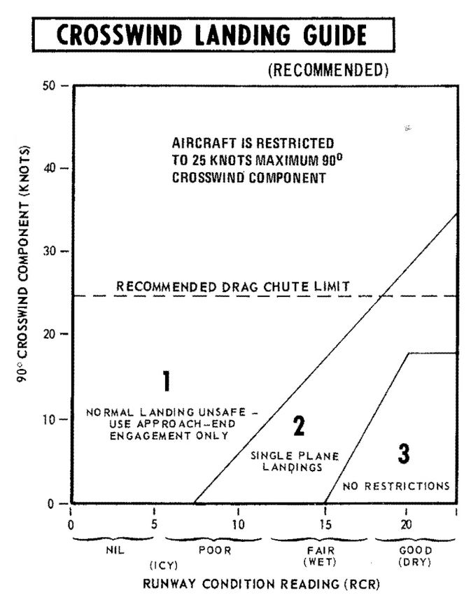
Wet or Icy Runway Landing
Wet or icy runway conditions pose severe problems in directional control and braking effectiveness. On wet runways, these problems are primarily the result of hydroplaning where the tire rides on a thin layer of water and produces little or no traction. The probability of hydroplaning increases with increased water depth, increased ground speed, decreased tire pressure and decreased tire tread depth and is also affected by runway surface texture and tire tread design. Hydroplaning can occur on runways which appear only damp if severe braking is applied at high speeds. Hydroplaning and glare ice present essentially the same problems. Due to the reduced directional control, all landings on a wet or icy runway should be made utilizing a crosswind technique. Refer to the Crosswind Landing Guide (figure 2-7) to determine the advisability of making an approach-end engagement. The pilot should also consider the desirability of delaying the landing to permit the runway to dry or diverting to another field. Gross weight should be reduced to the minimum practicable. Plan the pattern to be well established on final with the aircraft tracking straight down the runway centerline with an ON SPEED indication. Use a wings - level crab, if required, to maintain the track. Establish the rate of descent at 800 fpm (slightly steeper than normal) and plan to touchdown on the centerline within the first 500 feet. Make a firm touchdown (500-600 fpm) while maintaining the wings-level crab. Immediately after touchdown retard the throttles to idle. Do not attempt to align the aircraft heading with the runway as this will result in a drift off the runway if the aircraft is sliding or hydroplaning. Maintain full forward stick to increase nosewheel traction. As wheel cornering capability overcomes aerodynamic effects the aircraft will align itself with the runway. Do not attempt to hasten this process. When the aircraft heading is aligned with the runway centerline, deploy the drag chute. Be prepared to jettison the drag chute if the weathervaning effect interferes with maintaining the track straight down the runway centerline. Nose gear steering is the primary method of directional control and should be utilized as early as possible. Nose gear steering should be engaged only with the rudder pedals at or near neutral. When directional control is firmly established utilize maximum anti-skid braking. Brake pedals must be fully depressed to achieve maximum deceleration. At high speeds the braking potential will be very low and little deceleration will be felt. As braking potential increases with decreasing speed, the anti-skid system will increase deceleration accordingly. Unless the pilot is familiar with the variables in braking potential, the low deceleration at high speed may be mistakenly interpreted as a brake or anti-skid failure.
🟡 CAUTION: Rubber deposits on the last 2000 feet of wet runway make directional control a difficult problem even at very low speeds. Braking should be started in sufficient time so as not to require excessive braking on the last portion of the runway.
Heavy Gross Weight Landing
The heavy gross weight landing pattern is the same as the basic pattern shown in figure 2-6 with the exception that it should be expanded slightly to compensate for the lower maneuvering capability of the heavy gross weight aircraft at low speeds. As in the normal pattern, an on-speed indication on the indexer will provide the optimum angle of attack and airspeed for the aircraft in the landing configuration for both level flight and maneuvering flight. Refer to Performance Data, appendix A, for airspeed versus gross weight at approach AOA.
Go-Around
Any decision to go around should be made as early as possible. When the decision to go around is made, smoothly increase thrust to military (afterburner if required). Do not attempt to rotate the nose or stop rate-of-descent until adequate airspeed is built up. Continue to use the on speed indication as the optimum angle of attack until level flight is attained. As airspeed increases, establish normal takeoff attitude, retract gear when a positive rate of climb is established, retract slats and flaps at a safe airspeed (180 knots minimum) and go around. Rudder jumps may occur during flap retraction with lateral stick input. For a closed pattern, accomplish a climbing 180° turn to roll out on downwind at 220 to 250 knots. Refer to Go-Around, figure 2-8. During go-around a rapid trim change is required to preclude high forward stick forces.
🔴 WARNING: Do not exceed 18 units AOA during go-around with gear retracted.
Touch-And-Go
After making a normal approach and touchdown, smoothly advance throttles to full military power. Apply aft stick until the nose rotates 10° to 12° of pitch attitude maintaining this attitude until the aircraft is flying. When definitely airborne retract the gear, followed by the flaps as the aircraft accelerates through 180 knots minimum.
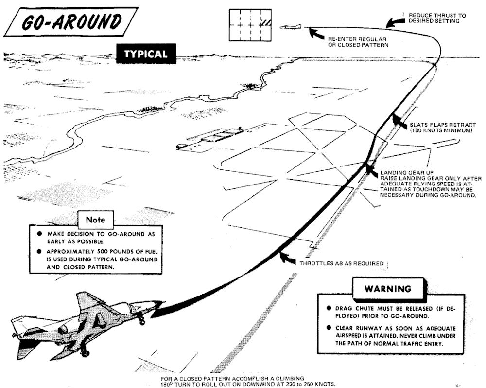
Instrument Approach and Landing
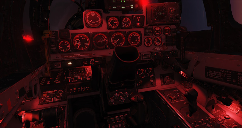
Holding / Loiter
Holding patterns or loitering flight may be flown at most altitudes at 280 knots, using approximately 30° of bank.
Instrument Descent
This figure represents typical penetration pattern.
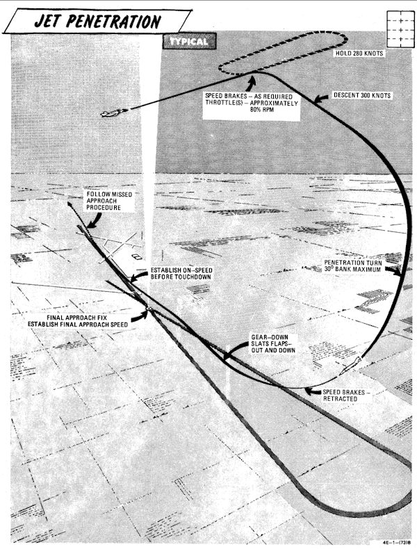
💡 Do not reduce thrust below 80% rpm (85% single engine) to ensure adequate windshield defogging/rain removal/engine anti-ice effectiveness. If the throttle is retarded to idle in heavy precipitation a lower than normal idle rpm indication may be noted.
💡 The pressure altimeter should be crossed checked with the radar altimeter to confirm terrain clearance at low altitude.
Precision Approach
This figure represents typical penetration pattern.
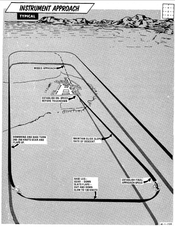
- Descend to GCA pick-up altitude and transition to landing configuration approximately 10 miles out on final or base leg (as appropriate).
- Maintain minimum on-speed angle of attack.
When directed to commence descent:
- Retard power to approximately 82-84% rpm.
- Adjust power and pitch as necessary to maintain desired rate of descent.
A straight-in TACAN penetration followed by a GCA or ILS final requires approximately 500-800 pounds of fuel. A missed approach followed by a second GCA requires an additional 1000 pounds of fuel.
Circling Approach
Recommended airspeed from TACAN final approach fix for a circling TACAN approach, is 180 knots with gear and flaps extended.
Missed Approach
- Throttles - MILITARY
- Gear - UP
- Slats flaps - NORM (minimum of 180 knots)
- Power as required to maintain 240-250 knots and maintain a 1500 to 2500 feet per minute climb.
- Follow published missed approach procedures.
Landing Checklists
Descent / Before Landing
| Step | System | Action |
|---|---|---|
| 1. | Defog & Temperature | AS DESIRED |
| 2. | ALE-40 Flares/Norm Switch | NORMAL |
| 3. | STAB AUG Switches | ENGAGED |
| 4. | COMM Antenna Select Switch | UPR |
| 5. | Landing/Taxi Light | LANDING |
| 6. | Armament Switches | OFF/SAFE/STOW |
| 7. | Sight | STBY/CAGE |
| 8. | Radar & BARO Altimeter | SET |
| 9. | Fuel | CHECK |
In Pattern (below 210 knots)
| Step | System | Action |
|---|---|---|
| 1. | Gear | DOWN |
| 2. | Slats & Flaps | OUT & DOWN |
| 3. | Hydraulic Pressure | CHECK |
| 4. | Warning Lights | CHECK |
| 5. | Anti Skid | ON & LIGHT OUT |
Missed Approach
| Step | System | Action |
|---|---|---|
| 1. | Throttles | MILITARY OR AB |
| 2. | Gear | UP |
| 3. | Slats & Flaps | NORM (180 knots MIN) |
| 4. | Throttles | AS REQUIRED |
Landing
| Step | System | Action |
|---|---|---|
| 1. | Above runway | Gently flare |
| 2. | At touchdown | Throttles to IDLE |
| 3. | Drag Chute | DEPLOY |
| 4. | Wheel Brake (below 70 knots) | ENGAGE |
After Landing
| Step | System | Action |
|---|---|---|
| 1. | Anti Skid (below 30 knots) | OFF |
| 2. | Cockpit Pressure | CHECK |
| 3. | Ejection Handle | SAFE (not applicable) |
| 4. | Landing/Taxi Light | AS REQUIRED |
| 5. | Slats & Flaps | NORM |
| 6. | Drag Chute | JETTISON |
| 7. | Mode 4 Sel | HOLD |
| 8. | ECM/ALE/RWR/APX-76 | OFF |
| 9. | Radar/CW Power | OFF |
| 10. | STAB AUG Switches | OFF |
| 11. | Internal Wing Dump | NORMAL |
| 12. | VOR/ILS Control Panel | OFF |
| 13. | Engine Anti-Ice | NORMAL |
| 14. | Radar Altimeter | OFF |
| 15. | STAB Trim | 1-3 units NOSE DOWN |
| 16. | Reference Sel Switch | STBY |
| 17. | Rain Removal | OFF |
| 18. | Pitot Heat | OFF |
| 19. | IFF | OFF |
| 20. | Temperature | FULL HOT |
| 21. | Defog Handle | DEFOG |
| 22. | TACAN | OFF |
| 23. | Formation Lights | OFF |
| 24. | Sight Shutter | CLOSED |
Shutdown
Engine Shutdown (Pilot)
| Step | System | Action |
|---|---|---|
| 1. | Wheels | CHOCKED🔧 |
| 2. | UHF Radio | OFF |
| 3. | Ejection Seat | RAISE |
| 4. | Defog-footheat | FULL AFT |
| 5. | Temperature | 12 O'CLOCK |
| 6. | Air Refuel Switch | EXTEND if AAR was done |
| 7. | Right Throttle | OFF |
| 8. | AVTR Tape | REMOVE |
| 9. | Spoiler Actuator | CHECK (RIGHT)🔧 |
| 10. | Left Throttle | OFF |
| 11. | Engine Master Switches | OFF |
Engine Shutdown (WSO)
| Step | System | Action |
|---|---|---|
| 1. | UHF Radio | OFF |
| 2. | Ejection Seat | RAISE |
| 3. | INS | OFF |
| 4. | NAV Computer | OFF |
| 5. | Target Designator | OFF |
Before Leaving Cockpit
| Step | System | Action |
|---|---|---|
| 1. | (P-WSO) All Switches and Controls | OFF |
| 2. | (P-WSO) Oxygen Diluter | 100% |
Special Procedures
This subchapter contains special procedures for operating the F-4E Phantom II.
 Pilots scramble to their F-4 Phantom II aircraft on alert during exercise William Tell '80
Single Engine Taxi
When required left engine may be shut down first.
| Step | System | Action |
|---|---|---|
| 1. | Right generator switch | OFF |
| 2. | BUS TIE OPEN light | OFF |
| 3. | Utility hydraulic pressure | WITHIN LIMITS |
| 4. | Right engine throttle | OFF |
Hot Refueling
Before refueling:
| Step | System | Action |
|---|---|---|
| 1. | Single-engine taxi procedures | COMPLETE |
| 2. | Internal wing transfer switch | NORMAL |
| 3. | External transfer switch | OFF |
| 4. | Air refuel switch | EXTEND |
| 4. | After entering hot pad area, establish voice contact (intercom with pilot and refueling supervisor). | |
| 5. | Refuel selection switch | AS DESIRED |
During refueling:
| Step | System | Action |
|---|---|---|
| 1. | Remain alert to all visual and voice signals from the refueling supervisor. | |
| 2. | Monitor ground control frequency. |
After refueling:
| Step | System | Action |
|---|---|---|
| 1. | Air refuel switch | RETRACT |
| 2. | Refuel selection switch | INT ONLY |
Scramble
The following scramble procedures assume that the following actions have been completed prior to the aircraft being placed on an alert status (subject to scramble type activities):
- Complete preflight inspection to include a power-on cockpit inspection, engine operational check, and operational check of speed brakes, flaps, flight controls and stab aug in accordance with normal BEFORE TAXIING (FRONT COCKPIT) checks.
- INS aligned and placed in heading memory.
- Aircraft is cocked for scramble per local policy and instructions.
If the above actions are not completed prior to scramble, normal procedure should be used.
Before Taxiing (Front Cockpit)
| Step | System | Action |
|---|---|---|
| 1. | Communication and navigation equipment | ON AND CHECK |
| 2. | Emergency attitude indicator | SET |
| 3. | Altimeter & SPC | SET & CHECK |
| 4. | Takeoff trim | CHECK |
| 5. | Slats flaps | OUT & DOWN🔧 |
| 6. | Clearance to taxi from WSO | |
| 7. | Reference system selector | PRIM |
| 8. | Seat pins | CHECK REMOVED & STOWED |
| 9. | Personal equipment | CHECK |
| 10. | Wheel chocks | REMOVE🔧 |
Before Taxiing (Rear Cockpit)
| Step | Description | Action |
|---|---|---|
| 1. | Communication and navigation equipment | ON & CHECK |
| 2. | APX-80 mode switch | PASSIVE/OFF |
| 3. | Pressure altimeter | SET & CHECK |
| 4. | Radar power | STBY |
| 5. | Radar overtemp light | OFF, MONITOR |
| 6. | NAV Computer Mode | STBY |
| 7. | Heading memory alignment | COMPLETE |
| If the inertial navigation set has not been previously aligned for heading memory, attitude reference can be obtained by performing a coarse alignment (ALIGN - wait 40 seconds - NAV). | ||
| 8. | NAV Computer Mode | AS DESIRED |
| 9. | Seat pins | CHECK REMOVED & STOWED |
| 10. | Personal equipment | CHECK |
| 11. | Notify pilot | CLEAR TO TAXI |
Before Takeoff
| Step | Description | Action |
|---|---|---|
| 1. | Flight instruments | CHECK & SET |
| 2. | Stab aug switches | ENGAGE |
| 3. | Flight controls | UNRESTRICTED (WSO visually check ailerons and spoilers) |
| 4. | (P-WSO) Canopies | CLOSE & CHECKED |
| 13. | (WSO) Command selector valve | AS BRIEFED |
| 5. | (P-WSO) Lower ejection handle guards | CLEAR (not applicable) |
| 6. | Fuel panel | SET & CHECKED |
| a. Internal wing transfer | NORMAL | |
| b. External transfer | AS REQUIRED | |
| 7. | Slats flaps | CHECK OUT AND DOWN |
| 8. | Anti-skid | ON; LIGHT OFF |
| 9. | Warning lights | CHECKED |
| 10. | Anti-ice | AS REQUIRED |
| 10. | Pitot heat | ON |
| 11. | IFF | AS REQUIRED |
| 14. | (P-WSO) Circuit breakers | CHECK |
AIM-54
AIM-7 Missile
AIM-7E Tuneup
| Step | System | Action |
|---|---|---|
| 1. | RADAR MISSILE POWER SWITCH | CW ON |
| a. RDR tuned lights | STDY FOR 4 MIN | |
| 2. | RADAR MISSILE POWER SWITCH | STBY |
| a. RDR tuned lights | OFF |
AIM-7F Tuneup
| Step | System | Action |
|---|---|---|
| 1. | RADAR MISSILE POWER SWITCH | CW OFF FOR 1 MIN |
| 2. | RADAR MISSILE POWER SWITCH | CW ON |
| a. RDR tuned lights | ON | |
| 3. | RADAR MISSILE POWER SWITCH | STBY |
| a. RDR tuned lights | REMAIN ON |
AIM-7 Launch
WSO
| Step | System | Action |
|---|---|---|
| 1. | RADAR POWER | OPR |
| 2. | RADAR MODE | RDR,MAP-B OR BST |
| 3. | POLAR SWITCH | LIN OR CIR 1 |
| 4. | ASPECT KNOB | AS REQUIRED |
| 5. | MANEUVER SWITCH | AS REQUIRED |
| 6. | STAB SWITCH | AS REQUIRED |
Pilot
| Step | System | Action |
|---|---|---|
| 1. | RADAR MISSILE POWER SWITCH | CW ON |
| a. RDR tuned lights | ON | |
| 2. | MISSILE INTERLOCK SWITCH | AS REQUIRED |
| 3. | SIGHT MODE | A/A |
| 4. | GUNS/MISSILE SWITCH | HEAT (OR AS REQUIRED) |
| a. Head-up RADAR light | ON | |
| 5. | MASTER ARM | ON |
| a. Head-up ARM light | ON | |
| 6. | TARGET LOCKON | ACCOMPLISH |
| For ACM Mode: | ||
| a. CAGE Button | PRESS | |
| b. Align target in Boresight | ||
| c. Nosewheel steering Button | PRESS TO ACCOMPLISH CAA LOCK | |
| 7. | GUNS/MISSILE SWITCH | RADAR |
| 8. | IN-RANGE LIGHTS | ON |
| 9. | SHOOT LIGHTS | ON |
| 10. | TRIGGER | SQUEEZE AND RELEASE |
AIM-9 Missile
AIM-9 Launch
Pilot
| Step | System | Action |
|---|---|---|
| 1. | SIGHT MODE | A/A |
| 2. | GUNS/MISSILE SWITCH | HEAT |
| a. Head-up HEAT light | ON | |
| 3. | MISSILE AURAL TONE | ADJUST |
| 4. | MASTER ARM | ARM |
| a. Head-up ARM light | ON | |
| 5. | UNCAGE SEEKER | |
| a. ARR BUTTON | PRESS AND HOLD | |
| b. NOTE: Seeker is only uncaged while ARR button is pressed and held | ON | |
| 6. | SHOOT LIGHTS | FLASHING |
| 7. | TRIGGER | SQUEEZE AND RELEASE |
Pilot with ACM Mode
| Step | System | Action |
|---|---|---|
| 1. | SIGHT MODE | A/A |
| 2. | GUNS/MISSILE SWITCH | HEAT |
| a. Head-up HEAT light | ON | |
| 3. | MISSILE AURAL TONE | ADJUST |
| 4. | MASTER ARM | ARM |
| a. Head-up ARM light | ON | |
| 5. | ACCOMPLISH RADAR LOCK | |
| a. CAGE Button | PRESS | |
| b. Align target in Boresight | ||
| c. Nosewheel steering Button | PRESS TO ACCOMPLISH CAA LOCK | |
| 5. | UNCAGE SEEKER | |
| a. ARR BUTTON | PRESS AND HOLD | |
| b. NOTE: Seeker is only uncaged while ARR button is pressend and held | ON | |
| 6. | SHOOT LIGHTS | FLASHING |
| 7. | TRIGGER | SQUEEZE AND RELEASE |
M61A1 Nose gun and SUU-23
Pilot
| Step | System | Action |
|---|---|---|
| 1. | SIGHT MODE | A/G OR A/A AS REQ |
| 2. | RETICLE DEPRESSION KNOB | SET (A/G ONLY) |
| 3. | RATE SWITCH | HIGH/LOW |
| 4. | DELIVERY MODE KNOB | OFF |
| 5. | WEAPON SELECT KNOB | NOT TV OR ARM |
| 6. | STATION SELECT BUTTONS | GUN |
| FOR GUN PODS: | ||
| a. STATION SELECT BUTTONS | SELECT STATIONS | |
| 7. | FOR A/A: | |
| b. GUNS/MISSILE SWITCH | GUN | |
| 8. | TRIGGER | SQUEEZE |
Bomb Procedures
There are different bombing modes found in the F-4E, in the following chapter you can find procedures for the different modes.
Bomb Delivery - Direct
| Step | System | Action |
|---|---|---|
| 1 | OPTICAL SIGHT | SET |
| a. Sight mode | A/G | |
| b. Reticle depression knob | SET | |
| 2 | DELIVERY MODE KNOB | DIRECT |
| 3 | WEAPON SELECT | BOMBS |
| 4 | AWRU | SET |
| a. Interval controls | SET | |
| b. Quantity knob | SET | |
| 5 | NOSE/TAIL ARM SWITCH | AS REQ |
| 6 | STATION SELECT BUTTONS | SELECT STATIONS |
| 7 | MASTER ARM | ARM |
| 8 | BOMB BUTTON | PRESS |
Bomb Delivery - Dive Toss and Dive Laydown
| Step | System | Action |
|---|---|---|
| 1 | SIGHT MODE | A/G |
| 2 | DELIVERY MODE KNOB | DT / DL |
| 3 | HSI MODE SWITCHES | NAV COMP |
| 4 | (WSO) RADAR MODE | AIR-GRD |
| 5 | (WSO) RADAR RANGE | 5 OR 10 NM |
| 6 | (WSO) RADAR POWER | OPR |
| 7 | (WSO) ANTENNA STAB SWITCH | NOR |
| 8 | (WSO)(DT ONLY) WRCS DRAG COEFF | SET |
| 9 | (WSO)(DL ONLY) WRCS RELEASE RANGE | SET |
| 10 | (WSO)(IF REQ) WRCS RELEASE ADVANCE | SET |
| 11 | WEAPON SELECT KNOB | BOMBS |
| 12 | AWRU | SET |
| a. Interval controls | SET | |
| b. Quantity knob | SET | |
| 13 | NOSE/TAIL ARM SWITCH | AS REQ |
| 14 | STATION SELECT BUTTONS | SELECT STATIONS |
| 15 | MASTER ARM SWITCH | ARM |
Dive on Target (DT ONLY)
| Step | System | Action |
|---|---|---|
| 1 | (WSO) RECEIVER GAIN | MIN |
| 2 | (WSO) LOCK ON TGT (CALL OUT) | |
| 3 | BOMB BUTTON (PRESS AND HOLD) | AFTER BOMB RELEASE |
| 4 | BOMB BUTTON (RELEASE) |
Bomb Delivery - Laydown
| Step | System | Action |
|---|---|---|
| 1 | SIGHT MODE | A/G |
| 2 | DELIVERY MODE KNOB | LAYDOWN(L) |
| 3 | RETICLE DEPRESSION KNOB | SET(IF REQ) |
| 4 | HSI MODE SWITCHES | NAV COMP |
| 5 | (WSO) WRCS TARGET RANGE | SET |
| a. Set the distance IP <-> TGT | ||
| 6 | (WSO) WRCS RELEASE RANGE | SET |
| 7 | (WSO) WRCS RELEASE ADVANCE | SET(IF REQ) |
| 8 | WEAPON SELECT KNOB | BOMBS |
| 9 | AWRU | SET |
| a. Interval controls | SET | |
| b. Quantity knob | SET | |
| 10 | NOSE/TAIL ARM SWITCH | SET |
| 11 | STATION SELECT BUTTONS | SELECT STATIONS |
| 12 | MASTER ARM SWITCH | ARM |
| 13 | BOMB RELEASE BUTTON | PRESS AND HOLD |
| AFTER BOMB RELEASE | ||
| 14 | BOMB RELEASE BUTTON | RELEASE |
Bomb Delivery - Loft
| Step | System | Action |
|---|---|---|
| 1 | (WSO) ACTIVATE SWITCH | NORMAL |
| 2 | (WSO) LOW ANGLE KNOB | SET |
| 3 | (WSO) PULLUP TIMER | SET |
| 4 | (WSO) RELEASE TIMER | SET ZERO |
| 5 | DELIVERY MODE KNOB | LOFT |
| 6 | WEAPON SELECT KNOB | BOMBS |
| 7 | AWRU | SET |
| a. Interval controls | SET | |
| b. Quantity knob | SET | |
| 8 | NOSE/TAIL ARM SWITCH | AS REQ |
| 9 | STATION SELECT BUTTONS | SELECT STATIONS |
| 10 | MASTER ARM SWITCH | ARM |
Over IP
| Step | System | Action |
|---|---|---|
| 1 | BOMB BUTTON | PRESS AND HOLD |
| 2 | AT PULL-UP POINT | INITIATE PULL-UP |
| AFTER BOMB RELEASE | ||
| 3 | BOMB BUTTON | RELEASE |
Bomb Delivery - LABS, TGT FIND and OFFSET
| Step | System | Action |
|---|---|---|
| 1 | Sight mode knob | A/G |
| 2 | Delivery mode knob | OFFSET BOMB or TGT FIND |
| 3 | (WSO) Target find switch | HOLD |
| 4 | Navigation mode knob | NAV COMP |
| 5 | HSI mode switches | NAV COMP |
| 6 | (WSO) INS mode knob | NAV |
| 7 | (WSO) Navigation mode selector switch | NAV COMP |
| 8 | (WSO) WRCS input counters | SET |
| a. Target distance N IS -100-foot increments | ||
| b. Target distance E/W - 100-foot increments | ||
| c. IP altitude MSL - 100-foot increments | ||
| d. Release range - 10-foot or 100-foot increments (OFFSET BOMB) | ||
| e. Release range - LABS pullup range, 10-foot or 100-foot increments | ||
| f. Release advance - Milliseconds (OFFSET BOMB if required) | ||
| 9 | Weapon select knob | BOMBS (OFFSET BOMB) |
| 10 | AWRU | SET |
| a. Interval controls - SET | ||
| b. Quantity knob - SET | ||
| 11 | Nose/tail arm switch | ON (as required) |
| 12 | Station select | LOADED STATION(S) |
| 13 | Master arm switch | ARM |
| 14 | (WSO) Dual timers | SET |
| a. Pullup timer - T1 | ||
| b. Release timer - T2 | ||
| 15 | (WSO) Release gyro | SET |
| a. Low angle (LOFT) - DEG |
Before Bomb Run
| Step | System | Action |
|---|---|---|
| 1 | (WSO) Radar power | OPR |
| 2 | (WSO) Radar mode | MAP PPI |
| 3 | (WSO) Antenna stab switch | NOR |
| 4 | (WSO) Cursor intensity | ADJUST |
| 5 | (WSO) Antenna elevation | ADJUST |
| 6 | (WSO) Scan switch | WIDE |
| 7 | (WSO) Radar range | AI 10 or AI 25 |
Bomb Run - Offset Radar IP
| Step | System | Action |
|---|---|---|
| 1 | (WSO) Operate along track control | Position range cursor over RIP |
| 2 | (WSO) Operate cross track control | Position offset cursor over RIP |
| 3 | (WSO) Freeze button | PUSH ON |
| 4 | (WSO) Target insert button | PUSH ON |
| The steering instruments display steering commands when the target insert button is pushed ON, and the cursor intersection will position over the target location and track the target. If the target is on the scope, set the target elevation on the ALT RANGE counter and touch up the cursors over the target. | ||
| 5 | Bomb release button | PRESS and HOLD (OFFSET BOMB) |
| a. At bomb release, pullup light - ON | ||
| b. When a station is empty, station ARM light - OFF | ||
| When the aircraft is on course to the target and at the preplanned release altitude and airspeed, press and hold the bomb release button until the bomb is released, as indicated by illumination of the pullup light. |
Bomb Run - Visual IP Flyover
| Step | System | Action |
|---|---|---|
| 1 | (WSO) When over IP, freeze button and target insert button | PUSH ON |
| 2 | Bomb release button | PRESS and HOLD (OFFSET BOMB) |
| a. At bomb release, pullup light - ON | ||
| b. When a station is empty, station ARM light - OFF | ||
| When the aircraft is on course to the target and at the preplanned release altitude and true airspeed, press and hold the bomb release button until bomb release occurs, indicated by the illumination of the pullup light. |
Bomb Run LABS/TGT Find
| Step | System | Action |
|---|---|---|
| 1 | Delivery mode knob (LABS) | Bomb Run LABS/TGT Find AS REQUIRED Select the planned delivery mode. NOTE: With the target find switch on HOLD, the delivery mode selector may be positioned to any LABS mode without losing WRCS function. |
| 2 | (WSO) Along track and cross track controls | Bomb Run LABS/TGT Find AS REQUIRED (Visual or Radar IP) |
| 3 | (WSO) Freeze button | Bomb Run LABS/TGT Find PUSH ON |
| 4 | (WSO) Target insert button | Bomb Run LABS/TGT Find PUSH ON |
| 5 | (WSO) After target insert, activate switch | Bomb Run LABS/TGT Find ON Select the ON position only after steering instruments have transitioned to the target. |
| 6 | At warning tone (T 1 start) | Bomb Run LABS/TGT Find INITIATE PULLUP |
| 7 | Bomb button | Bomb Run LABS/TGT Find PRESS and HOLD |
Zunis
KY-28 Operations
Prelaunch
| Step | System | Action |
|---|---|---|
| 1 | KY-28 Power | OFF and mode switch set to P |
| 2 | Code Setting | Determine that a proper code has been set by personnel qualified in voice security equipment. In DCS and in combination with SRS (Simple Radio) this is done through the ground crew communication menu in the DCS communications menu. |
| 3 | UHF Radio | ON |
| 4 | Mode Switch | P |
| 5 | Power Knob | ON |
| 6 | Ground Test | If a ground test of equipment is desired, establish two-way, plain-text radio communications on the plain-voice radio with a suitable remote station and request an equipment check. (In DCS another player is needed) |
| 7 | Mode Switch | C |
| 8 | Alarm Check | The KY-28 will perform an automatic alarm check when the mode switch is set to C and the power knob is set to On. The check will continue for about 2 seconds after power is applied. During this time a steady, unbroken 1200 Hz tone is heard in the headsets. Upon successful completion of the check, the 1200 Hz tone is interrupted at a 2.3 Hz rate. |
| 9 | Clear Interrupted Tone | Momentarily position the microphone button to UHF to clear the interrupted tone. When the microphone button is released, the KY-28 reverts to the standby condition and is ready for either transmission or reception. If the unit fails to pass the alarm check, the steady 1200 Hz tone continues and further cipher operation is inhibited. |
| 10 | Alarm Check Failure | Note: If the KY-28 fails the alarm check, the power knob must be set to OFF and the mode switch to P (plain) to enable conventional UHF communications. |
| 11 | Transmit Ciphered Messages | To transmit ciphered messages, position the microphone button to UHF and wait until a momentary tone is heard before voice input. With the power knob set to ON, the momentary tone is delayed 0.5 seconds after pressing the microphone button. During this time, an encryption check is performed and the sync preamble is transmitted to receiving stations. If the encryption check fails, a 1200 Hz tone interrupted at a 2.3 Hz rate is presented in the headsets and cipher transmission is not possible. If the encryption check succeeds, a momentary tone is heard in the headsets. |
| 12 | Cipher Radio Communications | After the momentary tone is heard, establish two-way cipher radio communications with a cooperating station and check for readability and signal strength and/or transmit your message. Upon releasing the microphone button, the KY-28 will return to the standby condition. Simultaneous transmission by two or more stations on the same frequency is not possible and may result in garbled messages or loss of synchronization. |
| 13 | Resume Normal Communications | Resume normal, non-crypto communications if desired at any time by setting the mode switch to P (plain) again. |
| 14 | In-Flight Check | Note: The above procedures may be used to perform an in-flight check of the equipment. |
Postlaunch
| Step | System | Action |
|---|---|---|
| 1 | Equipment Operation | The speech security equipment shall be operated as briefed. |
| 2 | Warning: | If ZEROIZE is pressed during flight, ciphered communication is not possible. The code can only be reset (or changed) through the ground crew communications menu after landing. |
After Landing
| Step | System | Action |
|---|---|---|
| 1 | Zeroize as briefed. | |
| 2 | Power Off | OFF |
LANTIRN
Built-In-Test (BIT) Procedures
This chapter contains every Built-In-Test (BIT) Procedure for the Radar System, including Air-to-Ground BITs and Air-to-Air BITs, the DSCG Screen itself, the Pave Spike Targeting pod, the TACAN system and the VOR/ILS System.
Radar Air-to-Air Bits
BIT 0 Aim Dot and Range Rate Calibration
| Step | System | Action |
|---|---|---|
| 1. | Radar Power Knob | STBY |
| 2. | DSCG Mode Knob | RDR BIT |
| a. Test Grid | Aligned ±1/16 inches | |
| 3. | Test Knob | DOT BAL and HOLD |
| a. Aim Dot | Centered | |
| b. Range Rate | ±20 knots | |
| 4. | Radar Power Knob | TEST |
| 5. | Test Knob | DOT BAL and HOLD |
| a. Aim Dot | In Calibration Area | |
| b. Range Rate | 900 ±50 knots | |
| 6. | Adjust Horizon Line | Zero Pitch |
| 7. | Radar Range Knob | AI 10 |
| 8. | DSCG Mode Knob | DSCG TEST |
| a. Search Display | Eight Shades of Gray | |
| b. Adjust BRT | Optimal | |
| c. Adjust CONTR | Optimal | |
| 9. | DSCG Mode Knob | RDR BIT |
| 10. | Radar Range Knob | AI 25 |
| 11. | Position EL Strobe | 30° Down |
| (Prevents radar antenna from hitting stops) | ||
| 12. | Stab Switch | OUT |
| a. Horizon Line | Removed | |
| 13. | Stab Switch | NOR |
| 14. | Radar Power Knob | STBY |
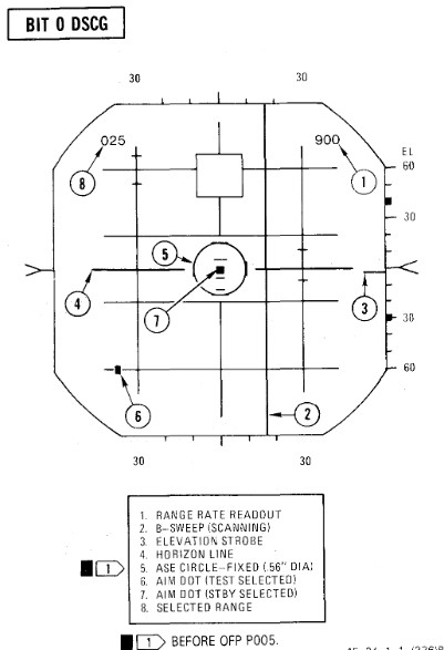
BIT 1 Minimum Discernible Signal, Lockon Sensitivity, Range Track Memory
| Step | System | Action |
|---|---|---|
| 1. | Test knob | Set 1 |
| 2. | Radar power knob | TEST |
| a. Monitor meter (RDR MAG) | Indicates 1.4 to 1.8. | |
| b. Horizon line | Within limit markers as shown. | |
| 3. | Adjust indicators | For optimum contrast (CONTR) and brightness (BRT). |
| a. Minimum targets | 11 targets visible in search. | |
| b. Position range knob | To 5, 10, 50, 100, 200, and 25 while checking video. | |
| 4. | Place acquisition symbol beyond the last target. | |
| 5. | Move range strobe down while holding full action. | |
| a. Range strobe locks on before passing seven targets. | ||
| b. Maintain lockon for 5 seconds. | ||
| 6. | Test knob | Set 0 |
| a. System unlocks in 4 to 6 seconds. | ||
| 7. | Test knob | Set 1 |
| 8. | Pulse switch | SHORT |
| a. Monitor meter (RDR MAG) | Indicates 0.9 to 1.15. | |
| b. Minimum targets | Eight targets visible in search. | |
| 9. | Place acquisition symbol beyond the last target. | |
| 10. | Move range strobe down while holding full action. | |
| a. Range strobe locks on before passing eight targets. | ||
| b. Maintain lockon for 5 seconds. | ||
| 11. | Test knob | 0 for 3 seconds then select TEST 1 |
| a. System goes into memory for 3 seconds, then re-acquires lockon. | ||
| b. Range rate readout flashes at 4 HZ for 3 seconds. | ||
| 12. | (P) Radar missile power | STBY FOR 1 MINUTE |
| 13. | (P) Radar missile power | CW ON |
| a. RDR light | ON STEADY 1 MINUTE | |
| 14. | Meter selector | KLY |
| a. Meter reads | 0.25 to 1.25 | |
| 15. | Lock on third target | |
| a. Aim dot in box | ||
| b. Range rate 900 ±200 knots | ||
| c. Break lock |
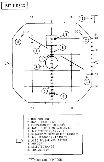
BIT 2 Range Track Acceleration, Antenna Position
| Step | System | Action |
|---|---|---|
| 1. | Test knob | Set 2 |
| 2. | Lock on 10th target | |
| a. System breaks lock in less than 30 seconds. | ||
| 3. | Lock on second target | |
| a. System maintains lock for at least 30 seconds. | ||
| b. Range rate readout 900 ±200 knots | ||
| 4. | Break lock | |
| 5. | Pulse switch | AUTO |
| BEACON CHECK | ||
| 6. | Radar mode knob | BEACON |
| a. BIT targets disappear and at least one beacon target reappears. | ||
| 7. | Radar mode knob | MAP |
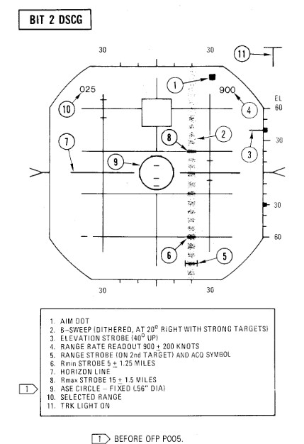
BIT 3 Angle Track
| Step | System | Action |
|---|---|---|
| 1. | Test knob | Set 3 |
| a. B-sweep and EL strobe at 0 ±0.2° (before lockon). | ||
| 2. | Lock on fourth target | |
| a. Aim dot rotates between ASE circle and the segmented circle (not exceeding either by more than 1/4 inch). | ||
| b. Rmax and Rmin at 15 and 5 miles. | ||
| c. ASE circle as shown. | ||
| d. EL strobe goes 30° down (after lockon). | ||
| 3. | Break lock and lock on 10th target | |
| a. Aim dot rotates inside ASE circle. | ||
| 4. | Maintain lockon for BIT 4. |
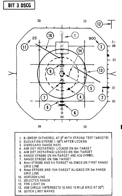
BIT 4 HOJ, Angle Track Memory, AOJ, Pseudo & Simulated Doppler, Corridor Scan
| Step | System | Action |
|---|---|---|
| 1. | Test knob | Set 4 (figure a). |
| a. All BIT targets disappear but lockon presentation remains. | ||
| b. H light ON | ||
| c. Range rate readout flashing, indicates 900 ±.200 knots, and last digit is replaced with the letter H. | ||
| 2. | (P) Radar missile power switch | OFF (or when AIM-7 missiles are turned). |
| 3. | Position B-sweep and EL strobe | At 0° for reference. |
| 4. | Radar power knob | STBY. |
| a. B-sweep and EL strobe drift less than +5° before unlock. | ||
| 5. | Radar power knob | TEST. |
| 6. | Action switch | FA (figure b). |
| a. AOJ display appears. | ||
| b. Range rate readout disappears And H light OFF. | ||
| 7. | Track switch | AOJ OUT. |
| a. System returns to search. | ||
| 8. | Track switch | AUTO. |
| 9. | Display | VI. |
| a. B-sweep covers 3 bars on selected CAA corridor. | ||
| b. EL-strobe scans from -21° to +57°. | ||
| 10. | Display | B-wide. |
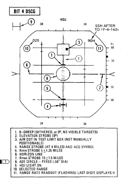 Figure a
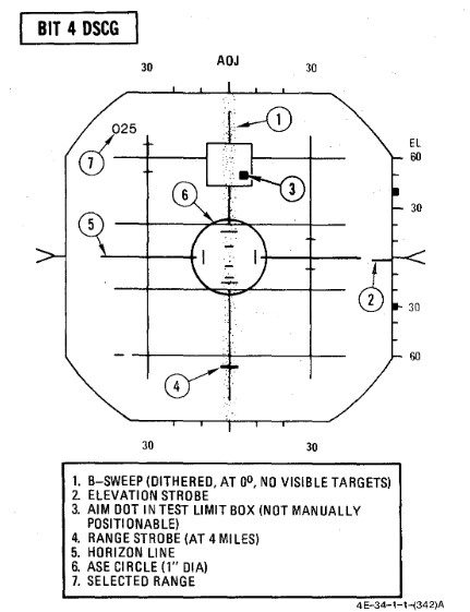 Figure b
BIT 5 Range Rate Noise, PLMS, CAA
| Step | System | Action |
|---|---|---|
| 1. | Test knob | Set 5 |
| 2. | Lock on third target | |
| a. Range rate readout 0 ± 300 knots. | ||
| b. Aim dot inside of ASE circle. | ||
| c. ASE circle 0.56 inch diameter. | ||
| 3. | Break lock | |
| 4. | Pulse switch | SHORT |
| 5. | (P) Sight mode knob | A/A |
| 6. | Radar mode knob | BST |
| 7. | Range knob | AI 5 |
| 8. | (P) Auto acq button | PRESS and RELEASE |
| a. Radar locks on first target | ||
| 9. | (P) Auto acq button | PRESS and RELEASE |
| a. Radar breaks lock, range gate sweeps to next target and locks on. | ||
| b. Repeat this step through all targets. | ||
| 10. | Air-to-air button | PRESS |
| a. Air-to-air light | OFF | |
| b. Radar control transfers to RCP. | ||
| 11. | Break lockon | |
| 12. | Radar mode knob | MAP |
| 13. | Range knob | AI 25 |
| 14. | Pulse switch | LONG |
| 15. | Lock on fifth target | |
| a. RDR MAG indicates 1.4 to 1.8. | ||
| 16. | Pulse switch | AUTO |
| a. RDR MAG indicates 0.9 to 1.15 (PLMS). | ||
| 17. | Aspect knob | TAIL |
| a. Range rate readout displays fighter heading (0°-360°) | ||
| 18. | Display knob | VI |
| a. Updates fighter heading display. | ||
| 19. | Display knob | B-WIDE |
| a. Discontinues fighter heading update. |
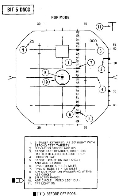
BIT 6 AIM-7 Attack Display and Interlocks
| Step | System | Action |
|---|---|---|
| 1. | Test knob | Set 6 |
| The T (track) light illuminates but SKIN TRK light remains OFF during this test. This is a normal indication with the DSCG. | ||
| 2. | Radar power knob | TEST |
| 3. | Missile power switch | STBY |
| 4. | Position range strobe | Beyond 15 miles. |
| a. Rmax at 15 ± 1.5 miles, Rmin at 5 ± 1.25 miles. | ||
| Range rate 000 knots Indicates AIM -7E missiles/plugs installed or stations empty. 900 knots indicates AIM-7F missiles/plugs installed. After OFP P005, the OFP version number will be displayed for the first 10 seconds in place of range rate readout; for example, OFP version P005 will be approximately 500 knots. | ||
| 5. | Move range strobe down | (with half action or full action) |
| a. Aim dot stationary inside box. | ||
| b. HOLD ALT light ON beyond 15 miles, OFF at 15 miles. | ||
| c. IN RANGE and SHOOT lights ON when range strobe is between Rmax and Rmin. | ||
| d. ASE circle remains fixed in size. | ||
| e. Break X occurs, ASE Circle and range rate readout disappear, IN RANGE/SHOOT lights OFF at 5 miles or less. | ||
| 6. | Radar power knob | STBY |
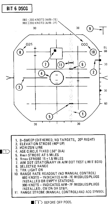
Radar Air-to-Ground Bits
BIT 5
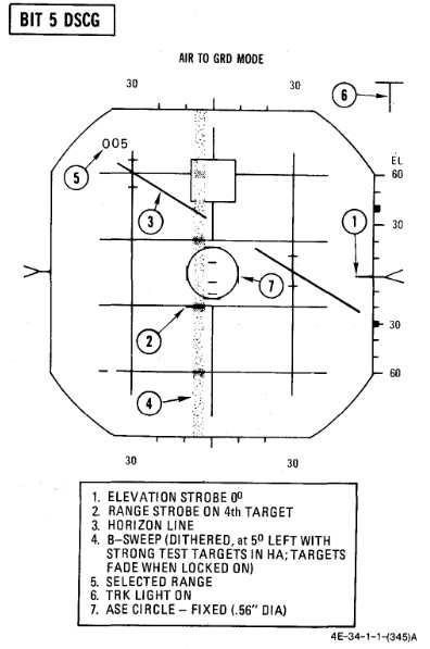
Range Slope and Zero
| Step | System | Action |
|---|---|---|
| 1. | (P) Sight mode knob | A/G |
| 2. | Radar power knob | TEST |
| 3. | Radar range knob | AI 5 |
| 4. | Radar mode knob | A/G |
| 5. | Test knob | 5 |
| a. Monitor (RDR MAG) 0.9 to 1.15 | ||
| b. B-sweep 5° ±3° left of center. | ||
| c. Acquisition symbol centered on B-sweep (before lockon). | ||
| d. Horizon line indicates 30° left bank and 30° dive. | ||
| 6. | Lock on first target | |
| a. ASE circle appears and B-sweep fades (AGC). AGC action reduces the B-sweep intensity and the weaker test targets fade. However, it is not abnormal for the stronger test targets to be visible in the B-sweep. | ||
| b. (P) Range bar at 5:00 within ±.5° (6000 feet). | ||
| 7. | Lock on second target | |
| a. (P) Range bar at 3:00 within ±.5° (12,000 feet). | ||
| 8. | Lock on third target | |
| a. (P) Range bar at 1:00 within ±.5° (18,000 feet). |
Bomb Range Strobe Calibration
| Step | System | Action |
|---|---|---|
| 1. | Test knob | 1 |
| 2. | Display knob | PPI WIDE |
| 3. | Radar mode knob | MAP |
| 4. | Radar range knob | AI 10 |
| a. PPI sweep scans 1200 sector. | ||
| b. PPI sweep drift Offset 5.6°. | ||
| c. Far edge of bombing Strobe just touches appropriate BIT target. |
WRCS BITs
WRCS BIT
| Step | System | Action |
|---|---|---|
| 1. | INS | ALIGN or NAV |
| 2. | Target alt/range knob | 170 |
| 3. | ARBCS bombing timers | SET |
| a. Pullup | 5.0 | |
| b. Release | 10.0 | |
| 4. | (P) BRG/DIST switch | NAV COMP |
| 5. | (WSO) Nav mode switch | NAV COMP |
Laydown Mission
| Step | System | Action |
|---|---|---|
| 1. | WRCS BIT selector | LAYDOWN |
| 2. | BIT button | PUSH and HOLD |
| 3. | After 5 seconds, FRZ button. | PUSH ON |
| a. Range indicator | ON | |
| b. After 15 seconds | GO/NO GO |
Dive Laydown Mission
| Step | System | Action |
|---|---|---|
| 1. | WRCS BIT selector | DIVE LAYDOWN |
| 2. | BIT button | PUSH and HOLD |
| 3. | After 5 seconds, FRZ button. | PUSH ON |
| a. Alt indicator | ON | |
| b. After 15 seconds | GO/NO GO |
Dive Toss Mission
| Step | System | Action |
|---|---|---|
| 1. | WRCS BIT selector | DIVE TOSS |
| 2. | BIT button | PUSH and HOLD |
| 3. | After 5 seconds, FRZ button. | PUSH ON |
| a. Alt indicator | ON | |
| b. After 15 seconds | GO/NO GO |
AGM-45 Mission
| Step | System | Action |
|---|---|---|
| 1. | WRCS BIT selector | AGM-45 |
| 2. | BIT button | PUSH and HOLD |
| a. BDHI and HSI miles 7.6 ± 1.0 NM | ||
| b. Alt indicator | ON | |
| 3. | After 5 seconds, FRZ button. | PUSH ON |
| a. BDHI and HSI miles DECREASE | ||
| b. AOA lower indexer | PULL UP COMMAND | |
| c. After 10 seconds, AOA center indexer | LEVEL COMMAND | |
| d. After 5 seconds | GO/NO GO | |
| e. After 5 seconds, AOA upper indexer | DIVE COMMAND |
Target Find/Offset Bomb Mission
| Step | System | Action |
|---|---|---|
| 1. | WRCS BIT selector | TGT FIND/OFFSET BOMB |
| 2. | BIT button | PUSH and HOLD |
| a. Alt indicator | ON | |
| 3. | After 5 seconds, along track cursor control | MOVE |
| 4. | Cross track control | MOVE |
| 5. | Cursor intensity | ADJUST |
| 6. | Reset button | PUSH |
| a. Cursors return to zero range and azimuth. | ||
| 7. | Target insert button | PUSH ON |
| a. Along track cursor | 6.5 NM on 00 grid line (±.2000 feet) | |
| b. Cross track cursor | 30° +1.5° RIGHT | |
| c. (P) HSI bearing pointer | 23° ±.2.5° (right of lubber); HSI TGT light - ON | |
| d. TGT INS light | ON | |
| e. BDHI #1 needle | 23° ±.5° (right of top index) | |
| f. (P-WSO) HSI and BDHI miles | 4.8±.1.0 NM | |
| g. (P) Sight roll tabs | ROTATED CLOCKWISE | |
| h. (P) ADI vertical pointer | DEFLECTS FULL RIGHT | |
| 8. | After 5 seconds, FRZ button. | PUSH ON |
| a. (P-WSO) HSI and BDHI miles | DECREASE TO ZERO, THEN INCREASE | |
| b. (P) Sight roll tabs | ROTATES (as miles passes through zero) | |
| c. After 15 seconds | GO/NO GO |
Bomb Range Calibration/Integration Check
| Step | System | Action |
|---|---|---|
| 1. | INS mode | NAV |
| 2. | WRCS control panel | SET |
| a. Target distance N/S | N120 | |
| b. Target distance E/W | 000 | |
| c. Target altitude | SET PRESENT AIRCRAFT HSL (29.92) | |
| d. Release advance | 000 | |
| e. Release range | 000 | |
| 3. | Weapons delivery panel | SET |
| a. Activate switch | NORM | |
| b. Target find switch | HOLD | |
| c. Range switch | X100 | |
| 4. | Front cockpit switches | SET |
| a. Delivery mode | T LAD | |
| b. Weapon select | BOMBS | |
| c. Station select buttons | OFF | |
| d. Armament override | PUSH IN | |
| 5. | Timers | SET (values for delivery) |
| a. Pullup timer | ||
| b. Release timer | ||
| 6. | Target insert button | PUSH ON |
| a. Along track cursor | Jumps to second BIT target | |
| 7. | WRCS distance counters N/S | Increase or decrease until near edges of along track cursor and second BIT target coincide. |
| a. Note difference between counter and N120. | ||
| b. For larger counter value, correction is +; for smaller counter value the correction is -. | ||
| 8. | Target distance N/S | RESET |
| a. Set preflight release range adjusted for calibration error in step 7. | ||
| b. Release range switch | NORM or X100 (as required) | |
| c. Activate switch | ON | |
| 9. | Release range counter | INCREASE (slowly until 1/3 second tone) |
| a. Check timer accuracy. | ||
| b. (P) Check LABS indications. | ||
| c. Note difference between derived RR counter reading and preflight release/activation range and apply as correction to all ranges. | ||
| (1) For larger counter value, correction is+; for smaller counter value, the correction is-. |
WRCS turn off
| Step | System | Action |
|---|---|---|
| 1. | WRCS BIT selector | RELEASE and OFF |
| 2. | Target alt/range counter | 000 |
| 3. | Weapons delivery panel | |
| a. Activate switch | NORM | |
| b. Target find switch | NORM | |
| c. Range switch | NORM | |
| 4. | WRCS control panel | RESET |
Navigation Tests
TACAN Test
| Step | System | Action |
|---|---|---|
| 1. | Function selector knob | T/R |
| Allow 90 seconds for warmup | ||
| 2. | Course | SET TO 180°. |
| 3. | Tacan test button | PRESS AND RELEASE |
| 4. | Observe the following: | |
| a. Test indicator | Flashes momentarily. | |
| b. Course and range flags | In view. | |
| c. Bearing pointer | Slews to 270° for about 7 seconds. | |
| d. Course and range flags | Out of view. | |
| e. Distance | Indicates 0.0 +0.5 miles (-0.5 miles indicated as 399.5 miles). | |
| f. Bearing pointer | Slews to 180° +3°. | |
| g. Course deviation indicator | Within 1/2 dot from center. | |
| h. TO-FROM indicator | Indicates TO. | |
| i. After about 15 seconds, Course and range flags in view until test complete. |
VOR/ILS Test
| Step | System | Action |
|---|---|---|
| 1. | ILS frequency Selector | Select frequency on indicator. |
| 2. | Press VOR/MKR Test pushbutton | Marker beacon lights illuminate. |
| 3. | VOR Frequency selected | Must be selected with a valid VOR Signal present. |
| 4. | Course selected | 315° on the HSI course selector. |
| 5. | HSI mode | In VOR/ILS. |
| 6. | Press the test pushbutton | Initiates the test. |
| a. Course deviation indicator moves to center (with a maximum allowable error of ±4°). | ||
| b. "To-from" indicator on HSI indicates TO. | ||
| c. Marker beacon lights illuminate | ||
| d. Bearing pointers on HSI and BDHI swing to 315° |
Optical Sight Test
| Step | System | Action |
|---|---|---|
| 1. | Pinky switch | RADAR |
| 2. | Sight shutter lever | OPEN |
| 3. | Sight mode knob | CAGE |
| 4. | Reticle depression knob | 35 MILS |
| 5. | Reticle intensity knob | AS REQUIRED |
| 6. | Armament switches | OFF/SAFE |
| a. Station green/amber lights | OFF | |
| 7. | Delivery mode knob | DIRECT |
| 8. | Armament safety override button | PUSH IN |
| 9. | Sight mode knob | CAGE to A/G to A/A |
| a. Pipper (at RBL) Moves no more than ±2 mils. | ||
| 10. | Reticle depression knob | 10 MILS |
| 11. | Sight mode knob | BIT 1 (figure 2-21) |
| a. Reticle jumps 25 ±4 mils left. | ||
| b. Roll tabs rotate 90° clockwise. | ||
| c. Range bar indicates 4000 feet (3 o'clock within ±15°.) | ||
| 12. | Sight mode knob | BIT 2 (figure 2-21) |
| a. Reticle drops down 25 ±4 mils. | ||
| b. Roll tabs indicate Level flight. | ||
| c. Range bar indicates 6700 feet (12:30 o'clock within ±15°). | ||
| 13. | Sight mode knob | A/A |
| a. Pipper returns to RBL. | ||
| 14. | (WSO) Radar power knob | TEST |
| 15. | (WSO) Test knob | SET 5 |
| 16. | (WSO) Range knob | AI 5 |
| 17. | (WSO) Radar mode knob | BST |
| 18. | (WSO) Lock on first BIT target | |
| 19. | Pinky switch | RADAR to HEAT |
| a. Pipper remains at RBL. | ||
| 20. | Pinky switch | GUNS |
| a. Head-up GUN light | ON | |
| b. Range bar indicates 6000 feet (1 o'clock within ±15°). | ||
| c. Reticle slowly depresses according to the corresponding AOA: | ||
| AOA Units | (Mils) | |
| 0 | (36) | |
| 5 | (31) | |
| 10 | (27) | |
| 15 | (22) | |
| 20 | (17) | |
| 25 | (13) | |
| 30 | (8) | |
| 21. | Cage button | PRESS AND HOLD |
| a. Pipper moves to 1000 feet cage range (approx 2 mils below RBL). | ||
| b. Range bar remains at 6000 feet (1 o'clock within ±15°). | ||
| 22. | (WSO) Break radar lock | |
| a. Range bar | OFF | |
| b. Pipper moves to | RBL. | |
| 23. | Cage button | RELEASE |
| a. Pipper moves to 1000 feet cage range (approx 2 mils below RBL). | ||
| 24. | Sight mode knob | STBY or CAGE |
| 25. | Delivery mode knob | OFF |
| 26. | Armament safety override button | RESET |
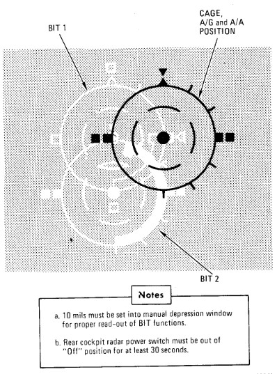
Mission Planning
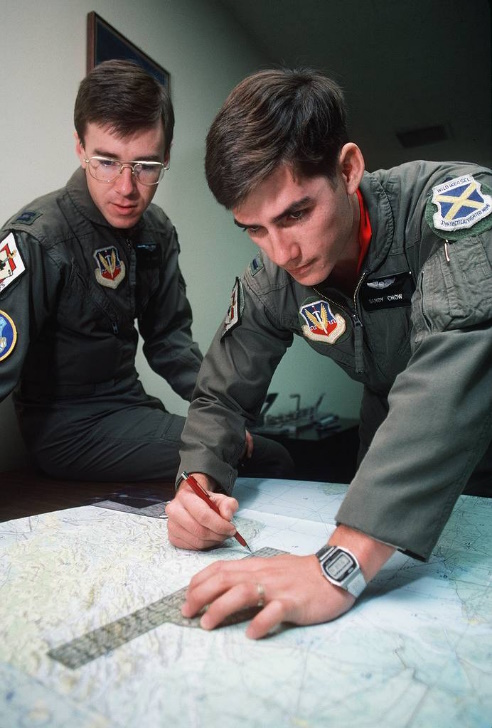 Captain Joe Fagan, left, and First Lieutenant Randy Chow prepare flight plans prior
to a "mission" in their F-4G Phantom II Advanced Wild Weasel aircraft simulator.
PHOTO from November 84 AIRMAN Magazine
Captain Joe Fagan, left, and First Lieutenant Randy Chow prepare flight plans prior
to a "mission" in their F-4G Phantom II Advanced Wild Weasel aircraft simulator.
PHOTO from November 84 AIRMAN Magazine
🚧 This section is under construction.
Optimum use of the aircraft to obtain maximum performance with minimum fuel consumption requires careful preflight planning for the mission. The planning of a mission involves many things which are beyond the scope of this publication. As used here, mission planning will cover certain key phases of a mission and explain the use of performance charts.
The following sample Counter Air mission demonstrates features of performance data. Although the sample problem does not cover the many mission capabilities of the aircraft, it familiarizes the aircrew with the use of performance data so that any mission may be preflight planned in a short time.
The sample problem illustrates, through a graphical solution, how performance charts can be integrated to form a complete mission flight plan. The steps used to develop such a plot are shown with the problem.
Counter Air Mission Profile
Perform maximum thrust takeoff and climb at military thrust. Cruise at optimum altitude and maximum range speed to a combat zone 500 miles from the air base. Drop external tanks when empty. Perform combat maneuvering at maximum thrust for the full duration — allowed by return and landing fuel requirements. Missiles and gun rounds are assumed to be expended at the end of the combat period. Return to the airfield at optimum altitude and airspeed. Descend at maximum range descent, arriving at the destination with 2000 pounds landing fuel reserve. The Counter Air Mission Overview and the Sample Mission Plan depict the overall mission plan.
Mission Data
Configuration
- (4) AIM-9 Missiles, Pylons and Launchers
- (4) AIM-7D Missiles
- (1) Nose-gun (639 rounds ammo)
- (2) 370 Gallon External Wing Tanks
- (1) 600 Gallon Centerline Tank
- Useable Fuel (includes external tanks) 20,768 pounds
Mission Factors
Takeoff:
| Parameter | Value |
|---|---|
| Wind | Calm |
| Pressure altitude | 2000 Ft |
| Temperature | +38.5°C |
| Runway | 020° |
| Runway length | 9000 Ft |
| Climb out wind | (headwind) 20 Kt |
| Cruise out wind | (headwind) 50 Kt |
| Cruise return wind | (tailwind) 50 Kt |
| Descent wind | (tailwind) 20 Kt |
Landing:
| Parameter | Value |
|---|---|
| Wind | 020°/10 |
| Pressure altitude | 2000 Ft |
| Temperature | +20°C |
| Runway | 020° |
| Runway length | 9000 Ft |
Figures
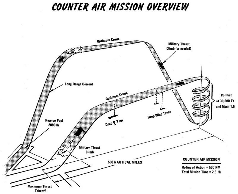
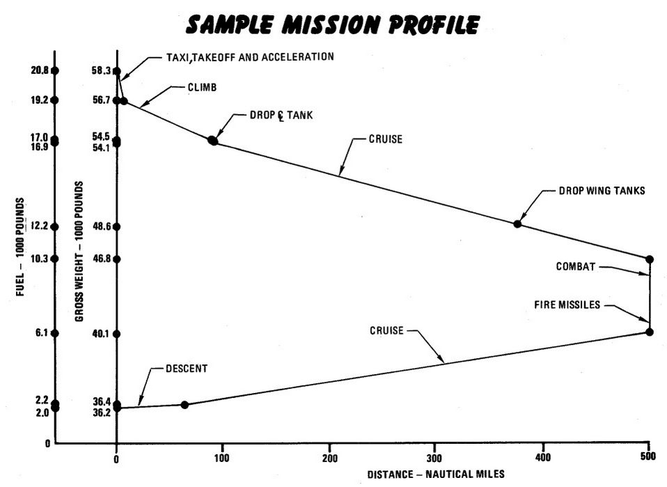
Emergency Procedures
🚧 This section is under construction
This section contains procedures to be followed to correct an emergency condition. These procedures will insure maximum safety for the crew and/or aircraft until a safe landing or other appropriate action is accomplished. The procedures are arranged in the most desirable sequence for the majority of cases; therefore, the steps should be performed in the listed sequence unless the pilot can determine a good cause for deviation. Multiple emergencies, adverse weather, and other peculiar conditions may require modification of these procedures. The critical items (BOLD FACE LETTERS) contained in the various emergency procedures cover the most adverse conditions. Aircrew members should be able to accomplish bold face procedures without reference to the checklist. The nature and severity of the encountered emergency will dictate the necessity for complying with the critical items in their entirety. It is essential, therefore, that aircrews determine the correct course of action by use of common sense and sound judgement. As soon as possible, the pilot should notify the WSO, flight or flight leader, and tower of any existing emergency and of the intended action.
The terms "Land as soon as possible" and "Land as soon as practical" are used in this section. These terms are defined as follows:
Land as soon as possible - An emergency will be declared. A landing should be accomplished at the nearest suitable airfield considering the severity of the emergency, weather conditions, field facilities, ambient lighting, aircraft gross weight, and command guidance.
Land as soon as practical - Emergency conditions are less urgent, and although the mission is to be terminated, the degree of the emergency is such that an immediate landing at the nearest adequate airfield may not be necessary.
The following basic rules apply to all aircraft emergencies and should be thoroughly understood by all aircrew:
- Maintain aircraft control.
- Analyze the situation and take proper action.
- Land as soon as practical.
See the Definitions for an explanation of the symbology used.
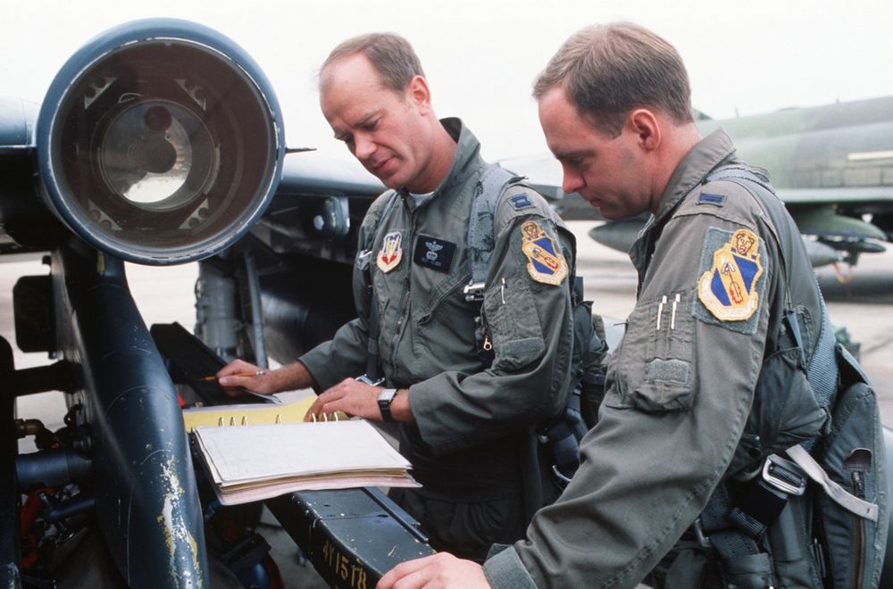 Captain (CPT) Drew Nelson, F-4E Phantom II aircraft pilot, and Lieutenant (LT) Steven Skinner,
weapons officer, both of the 336th Tactical Fighter Squadron, checks maintenance log on thier
aircraft during Exercise AMALGAM CHIEF'88. The exercise is a test of the Air Force's ability to
intercept enemy missiles and aircraft in the event of an attack on the continental United States
Captain (CPT) Drew Nelson, F-4E Phantom II aircraft pilot, and Lieutenant (LT) Steven Skinner,
weapons officer, both of the 336th Tactical Fighter Squadron, checks maintenance log on thier
aircraft during Exercise AMALGAM CHIEF'88. The exercise is a test of the Air Force's ability to
intercept enemy missiles and aircraft in the event of an attack on the continental United States
💡 This section contains only the most important emergency procedures.
🚧 This section is under construction.
Inflight Emergencies
OUT-OF-CONTROL RECOVERY
| Step | System/Condition | Action |
|---|---|---|
| 1. | STICK | FORWARD |
| 2. | AILERONS AND RUDDER | NEUTRAL |
| 3. | IF NOT RECOVERED | MAINTAIN FULL FORWARD STICK AND DEPLOY DRAG CHUTE |
| 4. | Throttles | IDLE (unless at low altitude) |
UPRIGHT SPIN
| Step | System/Condition | Action |
|---|---|---|
| 1. | STICK | MAINTAIN FULL FORWARD |
| 2. | AILERONS | FULL WITH SPIN (TURN NEEDLE) |
| 3. | AIRCRAFT UNLOADED | AILERONS NEUTRAL |
| 4. | If out of control at or below 10,000 feet AGL | EJECT |
ENGINE FAILURE DURING FLIGHT
SINGLE ENGINE FAILURE
| Step | System/Condition | Action |
|---|---|---|
| 1. | Airspeed | 300 KNOTS / 0.6 MACH MINIMUM |
| 2. | Land as soon as practical |
AIRSTART
| Step | System/Condition | Action |
|---|---|---|
| 1. | Engine master switch | ON |
| 1. | Throttle | OFF |
| 2. | Ignition button | HOLD DEPRESSED |
| 3. | Throttle | IDLE |
| 4. | RPM, EGT, oil pressure & fuel flow | MONITOR |
MECHANICAL MALFUNCTION
| Step | System/Condition | Action |
|---|---|---|
| 1. | Throttle bad engine | IDLE |
| 2. | Fire test button | PRESS |
If any FIRE/OVERHEAT light does not come on:
| 3. | Ignition button | HOLD DEPRESSED |
If engine malfunction is still evident (vibrations, noises, surges, etc.) or if engine has failed (insufficient rpm or fuel flow for start):
| 3. | Generator | OFF |
| 4. | Throttle | OFF |
| 5. | Engine master switch | OFF |
| 6. | Airspeed | 300 KNOTS / 0.6 MACH MINIMUM |
| 7. | Land as soon as practical |
DOUBLE ENGINE FAILURE DURING FLIGHT
| Step | System/Condition | Action |
|---|---|---|
| 1. | Either engine | AIRSTART |
| 2. | Reference system selector | STBY |
If neither engine starts:
| Step | System/Condition | Action |
|---|---|---|
| 3. | Fuel status | CHECK |
| 4. | Engine master switches | CHECK ON |
| 5. | Either throttle | OFF |
| 6. | Other engine | AIRSTART |
| 7. | Remaining engine | AIRSTART |
| 8. | If neither engine starts | Hold boost pump check switches in CHECK position while pulling left and right main fuel control circuit breakers, (H3, J1, No. 2 panel) then attempt airstart |
If neither engine can be started:
| 9. | Eject |
ENGINE FIRE OR OVERHEAT DURING FLIGHT
| Step | System/Condition | Action |
|---|---|---|
| 1. | Throttle bad engine | IDLE |
| 2. | If warning light goes out, fire test button | PRESS |
| 3. | If all FIRE/OVERHEAT lights come on when test button is pressed | LAND AS SOON AS PRACTICAL |
If warning light on, detection system inoperative, trailing vapor, or fire confirmed:
| 4. | Maintain 300 knots minimum, anticipate utility hydraulic failure, and avoid turns into bad engine. | |
| 5. | Generator bad engine | OFF |
| 6. | Throttle bad engine | OFF |
| 7. | Master switch bad engine | OFF |
| 8. | Air refuel switch | EXTEND |
| 9. | If fire persists | EJECT |
| 10. | If fire ceases | LAND AS SOON AS POSSIBLE |
🟡 CAUTION: Do not attempt to restart the bad engine. If the fire ceases, and a landing is to be accomplished, make a single engine landing.
COMPRESSOR STALL
| Step | System/Condition | Action |
|---|---|---|
| 1. | Throttle | IDLE |
If stall does not clear:
| 2. | Generator switch | OFF |
| 3. | Throttle | OFF |
| 4. | Inlet ramps | CHECK FULLY RETRACTED |
| 5. | Ignition button | HOLD PRESSED |
| 6. | Throttle | IDLE |
| 7. | RPM, EGT, oil pressure & fuel flow | MONITOR |
| 8. | Generator switch | ON |
GLIDE DISTANCE
With both engines failed, the aircraft will glide approximately 6 nautical miles for each 5000 feet AGL. The recommended glide airspeed for maximum range with both engines out is 215 knots. This speed will allow the windmilling engines to maintain power control hydraulic pressures within safe limits but may not be optimum for airstart.
EJECTION
At ground level with wings level, canopy closed, and no sink rate, ejection may be initiated between 0 and 550 knots if neither crewmember’s boarding weight is over 247 pounds. Boarding weight includes the crewmember and all personal equipment with which he boards the aircraft. If either crewmember’s boarding weight is over 247 pounds, the minimum ejection airspeed is 50 knots. Initiate ejection below 450 knots if possible. Although the seat is qualified to 600 knots, ejection above 450 knots exposes the crewmember to forces which can cause serious injury. If airspeed is over 550 knots, minimum ejection altitude is 50 feet. In controlled level flight, eject above 2000 feet AGL if possible. If out-of-control at or below 10,000 feet AGL, eject.
LANDING EMERGENCIES
SINGLE-ENGINE LANDING
| Step | System/Condition | Action |
|---|---|---|
| 1. | Reduce the airplane gross weight to minimum practical. | |
| 2. | Inlet ramp on good engine | CHECK FULLY RETRACTED |
| 3. | All unessential electrical equipment | OFF |
| 4. | Make a fully configured 17 unit AOA apporach |
EMERGENCY LANDING PATTERN
The emergency landing pattern is a pattern to be flown when engine thrust is available and an emergency exists or there is a malfunction which could result in an emergency. The primary objective of the pattern is to land the aircraft safely in the first attempt with least amount of risk. Because of the many variables involved, such as type of emergency, position and altitude in relation to the field, gross weight, fuel remaining, weather, populated areas, runway length, availability of arresting gear, etc., astandard pattern cannot be prescribed. Depending on the circumstances it might be desirable to utilize GCA, make a straight-in approach, enter the pattern from downwind or base leg, or make a 360° overhead pattern. Because of the various circumstances, the pilot’s evaluation of all factors and his judgment will determine the type of landing pattern to be flown. However, there are some general guidelines which are applicable regardless of approach selected: Reduce gross weight to minimum practical. In the pattern and before establishing the landing configuration, maintain a minimum maneuvering airspeed of 230 knots (250 knots, single engine). The pattern should be planned to avoid abrupt, steep or hard turns and large or abrupt power changes especially with a flight control malfunction or a hydraulic system failure. Circumstances permitting, a long straight-in final should be planned and the landing configuration established when on final. The air refuel switch should be placed to EXTEND prior to landing to depressurize the fuel tanks. Should the nature of the emergency or other factors dictate establishing the landing configuration prior to final, 230 knots — flaps up, or 200 knots - slats flaps OUT AND DOWN should be maintained until established on final. These airspeeds will provide a margin of safety for maneuvering flight. If the pattern must be entered on downwind, base or from an overhead pattern, the pattern should be expanded, the landing configuration established prior to final, and roll-out on final should be at least 2- 3 miles out. A normal 2-3° glide slope should be flown. For most emergencies, final approach airspeeds are increased and AOA decreased to provide adequate aircraft handling characteristics.
FLAME-OUT APPROACH
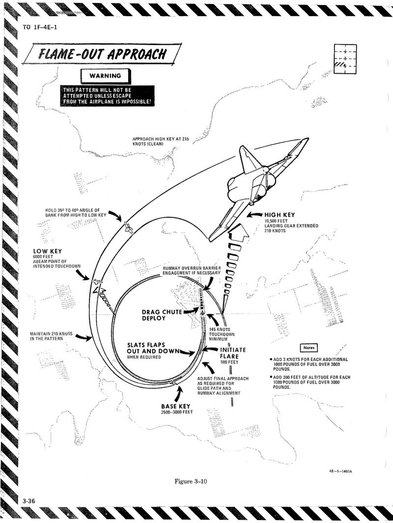
Supplement
Warning/Indicator Lights
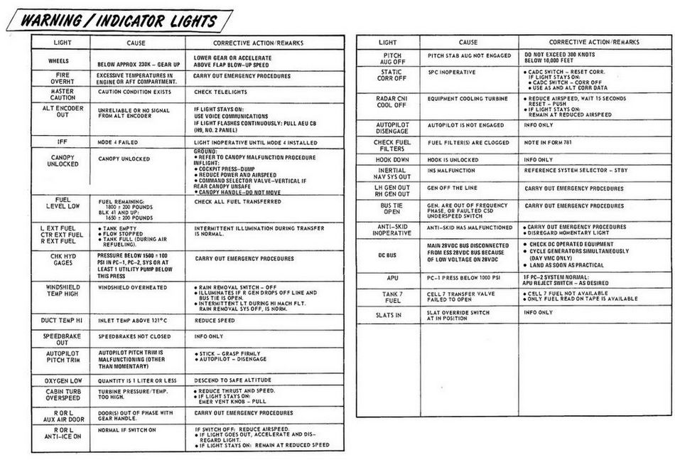
Emergency Power Distribution
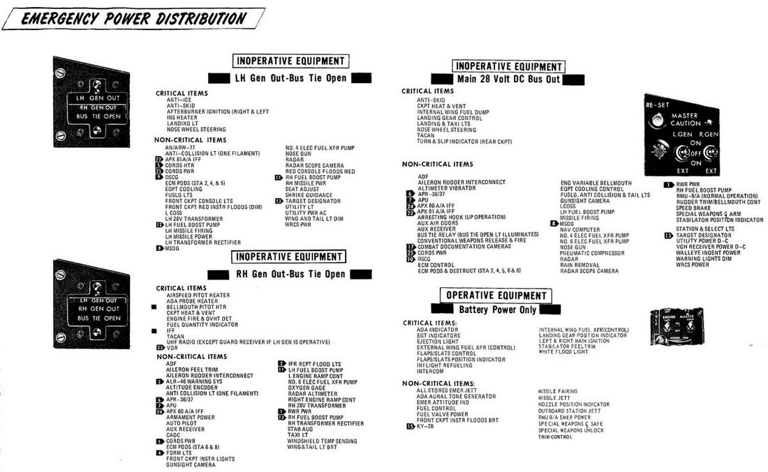
Airstart Enevlope
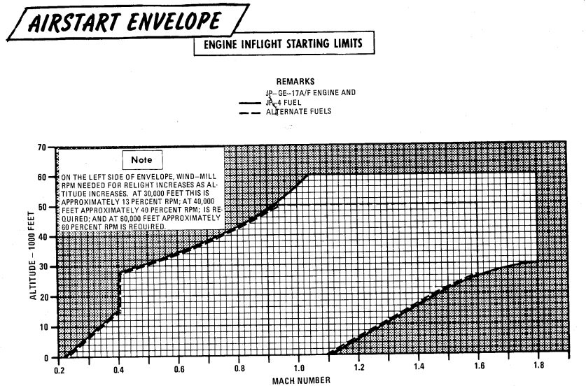
Jettison Chart
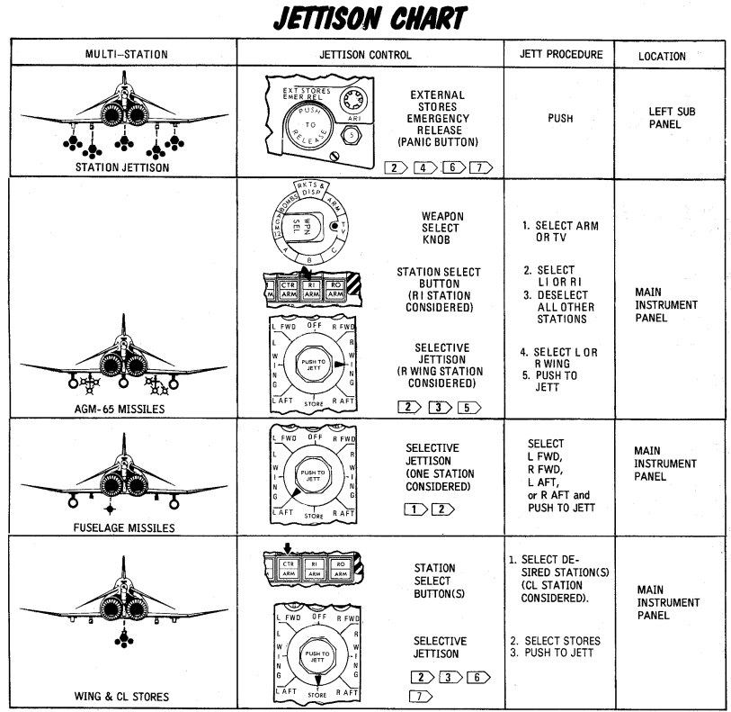
DCS
This chapter contains systems, settings and interfaces specific to the simulation of the Phantom inside DCS.
Of special note is a modding guide and explanation available to mission designers.
 Bicentennial themed F-4 Phantom II
Controls
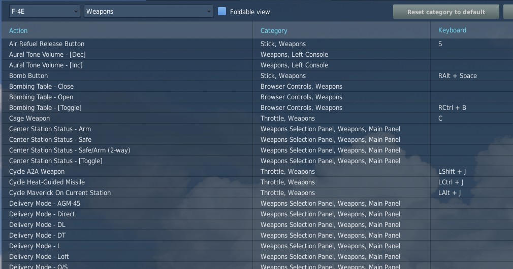
Available control binds for the Phantom are exhaustive. For any switch, knob or button, you can choose between direct position-binds, increment or decrement binds, a toggle or next option, special binds for 2-way or 3-way switches and assignable axis.
In total, both cockpits feature around 1000 assignable binds and 200 axis each.
As example, the Speed Brake switch provides 8 binds:
- Speed Brake - In
- Speed Brake - Stop
- Speed Brake - Out (Hold)
- Speed Brake - [Aft]
- Speed Brake - [Forward]
- Speed Brake - [Next]
- Speed Brake - In/Stop (3-way up)
The Out-position is marked (Hold) to signal that the position is spring-loaded and will return to center once released.
Binds [Aft] and [Forward] are directional binds that move the switch from the current position into the given direction.
[Next] is similar, but will not stop at the last position and wrap over to the first position again. Likewise, 2-way switches provide a [Toggle] bind that flips the switch between either position.
The (3-way up)-bind is intended to be used with actual 3-way hardware switches, such as present on many external devices. They send a signal on either position (up and down), but no signal on the center position. Hence, the bind will return the switch back to the center when no signal is send.
💡 The (3-way down)-bind is skipped for the Speed Brake, since it would be identical with the spring-loaded Out (Hold)-bind.
All binds are generally assigned at least two searchable categories, the system the bind belongs to and its location in the cockpit. The Master Arm switch for example has categories:
- Weapons
- Main Panel
- Weapon Selection Panel
Sim-Pit
Additionally to regular binds, special [SimPit]-binds are provided that allow controlling any switch or knob via an axis input.
For example, a switch with 2 positions ON and OFF can be controlled with an axis, while the switch changes its position as soon as the axis is pushed beyond its center position.
This is especially useful for builders of cockpit replicas, working mainly with hardware switches whose electronic components send normalized inputs through the entire movement range.
Jester & Crew Chief Commands
Direct binds to control Jester and Crew Chief commands are provided especially for mission designers or users of voice recognition software, such as VoiceAttack.
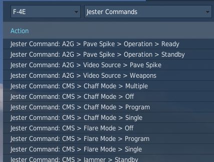
This allows use of the corresponding actions directly via a bind instead of using the UI to select them.
Binding Guide
When just getting started, a common question is which fundamental controls one should generally bind and have accessible without using the mouse, besides the obvious binds of throttle and stick axis.
💡 Items marked bold are highly recommended to be bound. Italic sections are suggestions of which positions to bind.
Pilot
The pilot should focus at binding the major flight controls, as well as combat relevant switches.
Flight Controls
- Stick
- Throttle
- Trim Controls (4 + 2)
- Landing Gear
- Flaps/Slats (Norm, Out, Out & Down)
- Airbrake (Out, Stop, In)
- Eject
- Nose Gear Steering / Auto Acquisition Button
- Drag Chute (Deploy, Cut)
- Seat Controls (Up, Down)
Startup
To execute the cold-start sequence, binds of interest are:
- Crew Chief Command: External Power > Connect
- Crew Chief Command: Air Source > Connect to Right/Left Engine
- Crew Chief Command: Air Source > Start/Stop Airflow
- Crew Chief Command: Air Source > Load Starter Cartridges
- Start Engine Switch Right/Left (fires up Starter Cartridges)
- Generator Right/Left (On, Off, Ext)
- Right/Left Engine Master Switch
- Right/Left Engine Ignition
- Right/Left Engine Idle Detent
Combat
- Trigger (2nd stage)
- Bomb Button
- Weapon Slew (4)
- Pinky Switch (Gun, Heat, Radar, Reject)
- CAGE Button
- Nose Gear Steering / Auto Acquisition Button
- DSCG Mode (Radar, Off, TV)
- Bombing Tool
- Dispense Countermeasures
- HUD Mode (CW, CCW)
- Delivery Mode (CW, CCW)
- Weapon Selector (CW, CCW)
Navigation
- Navigation Input (Next)
- Navigation Mode (Next)
- AFCS Switch
- ALT Hold Switch
- AAR Release Switch
Communication
- Microphone Switch (UHF, ICS)
- COMM Channel (Inc, Dec)
Jester
- Jester UI Action
- Jester Context Action
WSO
For the WSO it is optional to bind flight controls such as the flight stick. Controls should be focused at operating the Radar and the Pave Spike targeting pod.
Radar & Pave Spike
- Antenna Hand Control
- Antenna Hand Control Trigger (Half Action, Full Action)
- Antenna Elevation (Inc, Dec)
- Antenna Hand Control Challenge Button
- Screen Mode (CW, CCW)
Radar Controls
- Radar Receiver Gain (Inc, Dec)
- Radar Range (CW, CCW)
- Target Aspect (Next)
- Radar Mode (CW, CCW)
Combat Relevant
- Dispense Countermeasures
- Video Select
- Air to Air (CAGE) Mode
- Freeze Button
- Insert Target Button
- Move Cursor (Along/Cross Track) (Inc, Dec)
Navigation Controls
- Microphone Switch (UHF, ICS)
- COM Channel (Inc, Dec)
- Navigation Function (CW, CCW)
Real Controls
Here are the pictures of the real aircraft controls gathered for reference. For more detailed information see associated subchapters of 2. Cockpit Overview by using the respective hyperlinks.
Pilot Stick
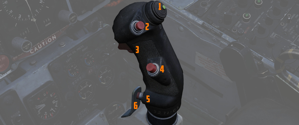
Pilot Throttle
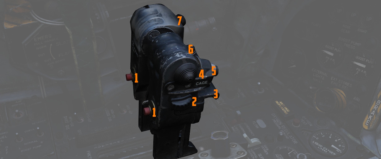
WSO Stick
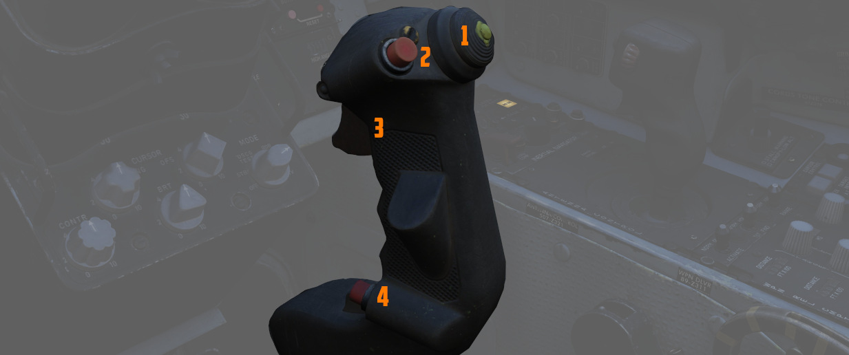
WSO Throttle
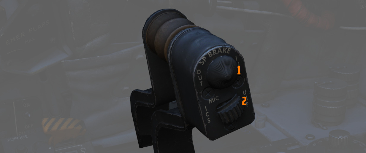
WSO Antenna Hand Control
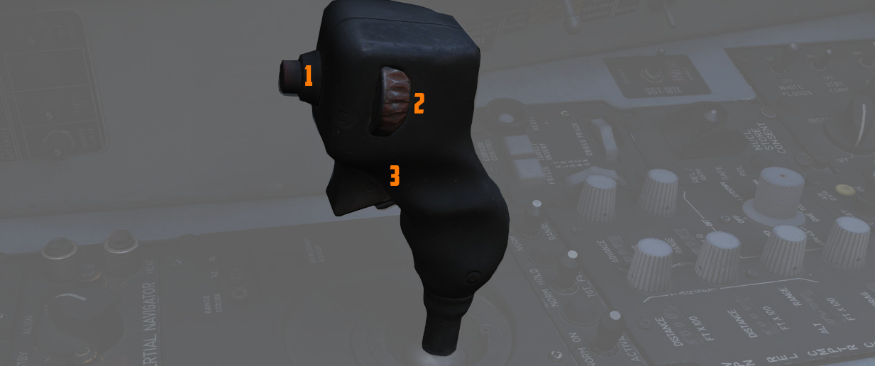
Special Options
The Heatblur F-14 in DCS has a set of options available affecting only the F-14. These are located under OPTIONS -> SPECIAL -> F-14 on the main DCS menu.
| Control | Function |
|---|---|
| Radio Menu and PTT Behavior | Sets up how the radio PTT buttons affect the DCS radio menu, useful if PTTs are used for SRS. |
| Jester AI Options: | |
| Use Head Movement in Order to Select Items in Jester Menu | Enable use of head movement with VR or Track-IR to select Jester Menu items. |
| Boring Jester | Disables Jester embellishments and jokes. Currently not implemented. |
| Switch PD-STT to P-STT lock when going WVR | Jester will automatically switch to P-STT within ACM ranges. |
| Jester Menu Camera | Enables or disables live Jester view on the Jester Menu Radial. |
Embedded Manual
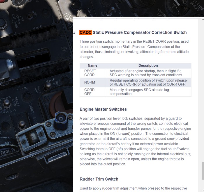
This manual is embedded into the game and can be read while flying.
It also offers a way to explain switches in the cockpit directly by opening the manual scrolled right to the spot explaining the corresponding switch.
Controls
The default bind M can be used to toggle the manual. When holding it down while clicking a switch in the cockpit, the manual will automatically open and scroll to the section explaining that switch.
Additionally, the following binds are available as well:
- RSHIFT + M - open the manual
- RCTRL + M - close the manual
- RALT + M - toggle the manual
💡 In order to close the manual, make sure to first remove keyboard focus from it by clicking anywhere else in the cockpit.
Bombing Computer
The bombing calculator provides the pilot and WSO with an easy way to calculate the needed values for the different bombing modes. You can use it to calculate every value (except for drag coefficient) that you need to drop precise ordinance on your target. It is opened with the hotkey RCtrl+B and can be closed with the same hotkey in-game. You can also bind it to a desired button in the controls tab.
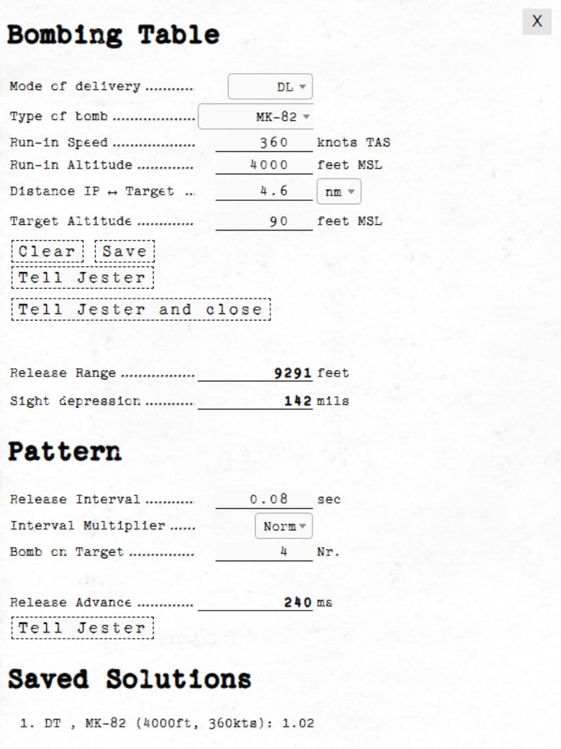
Bombing Table
Input
Mode of Delivery
The first thing that should be selected is the Mode of delivery. You can choose between the following modes depending on your attack run.
- Direct
- Dive Toss (DT)
- TGT Find
- Dive Laydown (DL)
- Laydown (L)
- Offset
- Loft
- Over-the-shoulder (O/S)
- Over-the-shoulder instantaneous (O/S INST)
Type of bomb
At the Type of bomb selection you can choose which ordinance you want to drop. Always choose the correct ordinance to get correct results. You can select out of the following selection:
- MK-81
- MK-82
- MK-83
- MK-84
- M117
- CBU-87
- MK-82 AIR
- MK-82 Snakeye (SNK)
- BLU-107
Run-in Speed
Sets the speed at which you want to fly from the ingress point to bomb release. The speed is the true air speed and can be set in increments of 5 knots per click.
Run-in Altitude
Sets the altitude at which you want to start your bombing run. The run-in altitude must be held from the identification point till bomb release. You can set it in increments of 100ft per click.
Distance IP <-> Target
Sets the distance between the identification point and the target point. You can select from either setting it in nautical miles with a 0.1 nautical miles increment or switch the unit to feet with the drop-down on the right. The increment in feet is in 100ft per click. Unit conversion also converts your actual input.
Target altitude
Sets the target altitude in feet above msl. You can set it in increments of 10ft per click.
Dive Angle
Sets the desired dive angle for the attack run. Can be set in 1° increments per click. Needs to be set in Direct and Dive Toss mode.
Loft angle
Sets the desired lofting angle for the attack run. Can be set it in 1° increments per click. Only used for LABS modes.
Must also be set in the LABS panel.

Output
In general the Bombing Calculator will only give you the Output you need to set for the selected attack run.
Pull-up timer
Gives you the calculated pull-up timer in seconds that the WSO can put in the ARBCS computer.

Release range
Gives you the calculated bombing range in feet that the WSO can put in the WRCS panel.
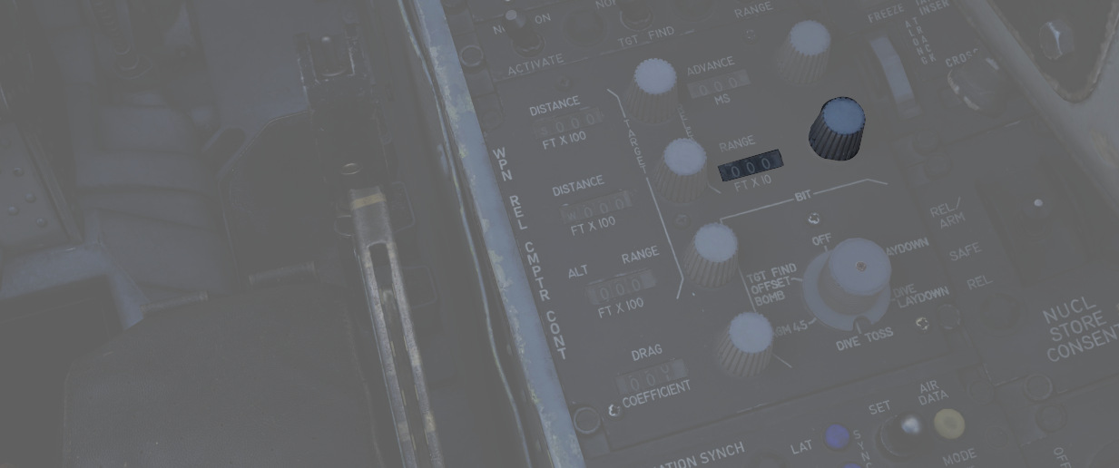
Sight depression
Gives you the calculated manual sight depression in mils.
This can be put into the sight depression knob in order to align the reticle with the target for a manual MIL bombing solution.
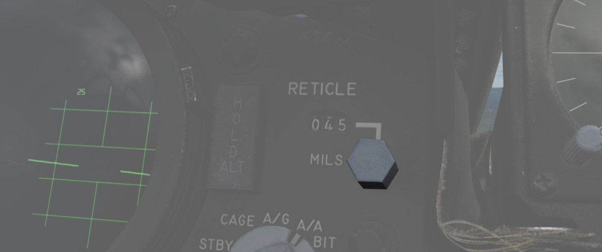
Drag Coefficient
Gives you the Drag Coefficient that the WSO then can set in the WRCS panel.
N/S WRCS and E/W WRCS
Gives you the calculated offset distance values that the WSO then can set in the WRCS panel.
Controls
Clear
Resets all inputs to standard values.
Save
Saves the actual solution under the Bombing Solutions tab at the end of the page.
Tell Jester and Tell Jester and close
With this button the values calculated by the bombing calculator can be transferred to Jester. He will either confirm the input or tell you "can't do" when the input is not correct.
Pattern
Lets you put in values to calculate a release advance.
Pattern Input
Release Interval
Sets the release interval that the pilot sets. You can set it in 0.01 increments per click.
Interval Multiplier
Sets the interval multiplier that the pilot sets. You can select "Norm" or "x10" in the drop-down.
Bomb on Target
Lets you select the number of bomb that you want to hit the target. Every bomb before the selected bomb will hit in front of the target. The rest of the bombs will hit behind the target.
Pattern Output
Release Advance
Gives you the calculated release advance that the WSO can put in.
Bombing Solution
Shows the last saved bombing solutions. The line shows the inputs as following:
- Mode of Delivery
- Type of bomb
- Run-in Altitude
- Run-in Speed
Depending on mode it will also save the corresponding solutions that are needed to fly the attack run.
Example run
This is a step-by-step guide for an example loft bombing run with 12 Mk-82s. In our case we want the fourth bomb to hit the target. The first three should hit in front of the target and the rest should impact behind the target. For that we will use the release advance.
Planning: Advance
The first step in planning our loft bombing run is to identify and pick a target. In this example run we want to bombard the red units standing on the X.
Planning: IP
In the second step we will take a look at the F10-Map and make out an Identification Point (IP).
💡 The IP should always have a good visibility while flying the plane as optical identification of the IP will be the main method of timing the press of the bomb button.
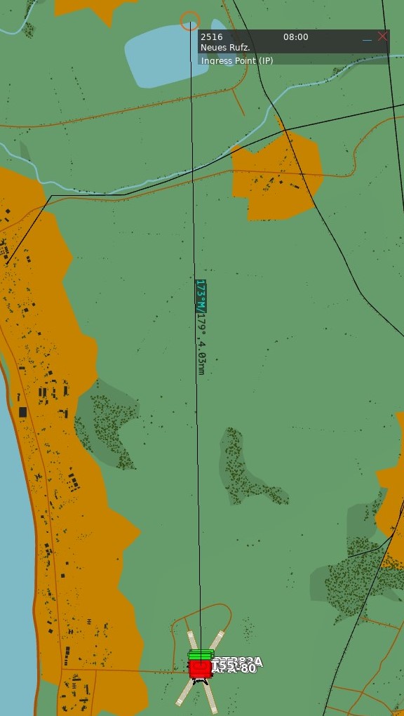
For our target we chose the lake just north of the target as an IP. Now we measure the distance from our IP to the target and note it down as we need to input that to the bombing calculator. In this case the distance is 4.03 NM which we will cut off to 4 NM since the bombing calculator can only take 10ths of a mile.
Planning: Target
Now we also need to note the elevation of the target in MSL. To get that information we just click on a unit and read the altitude out of the box in the lower left corner. In this case the target elevation is 32 ft which we will cut down to 30 ft since the bombing calculator can only take values of tens.
💡 If the target unit is not visible on the F10 map you can also hover over the position of the enemy unit and read the elevation next to the coordinates in the upper left corner of the map.
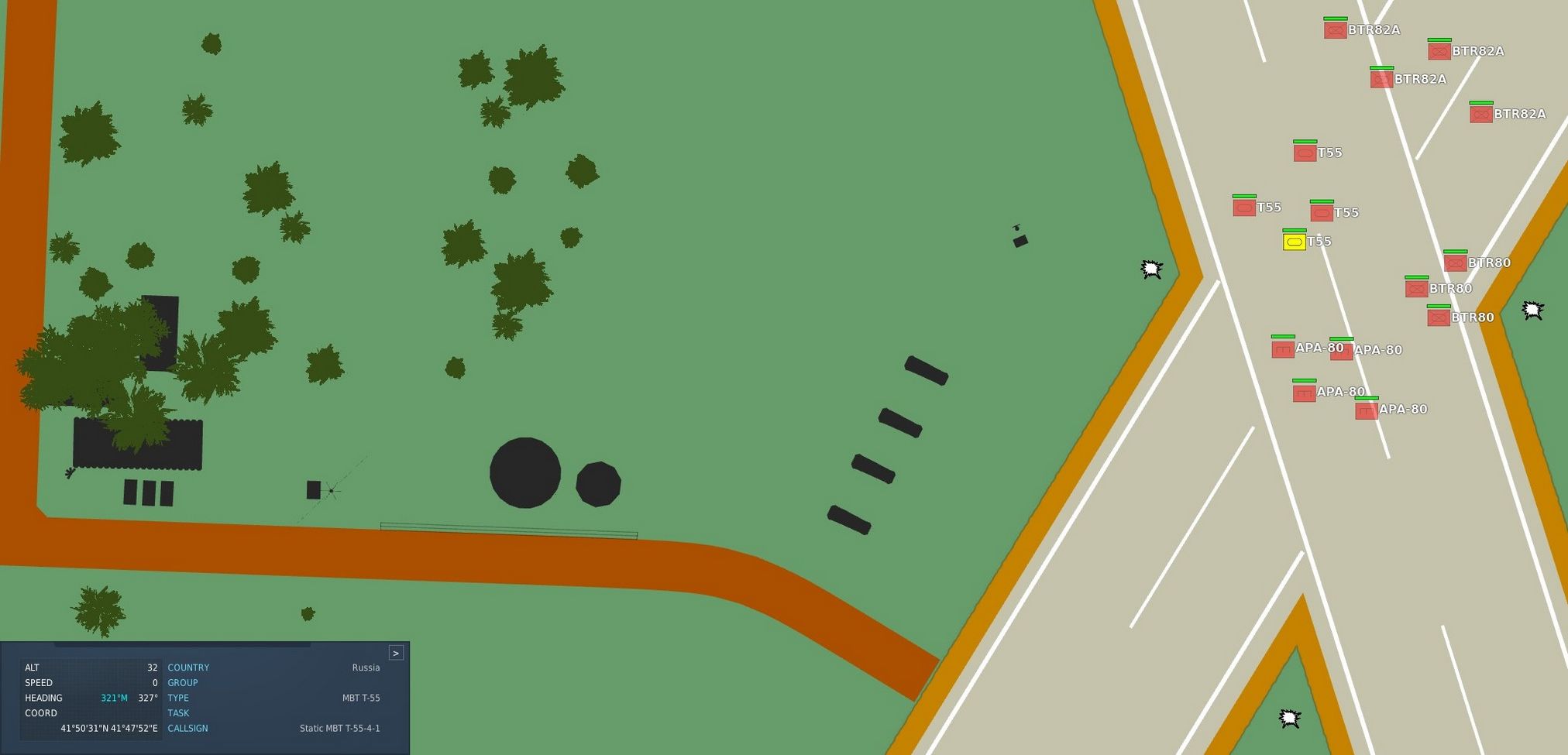
Solution
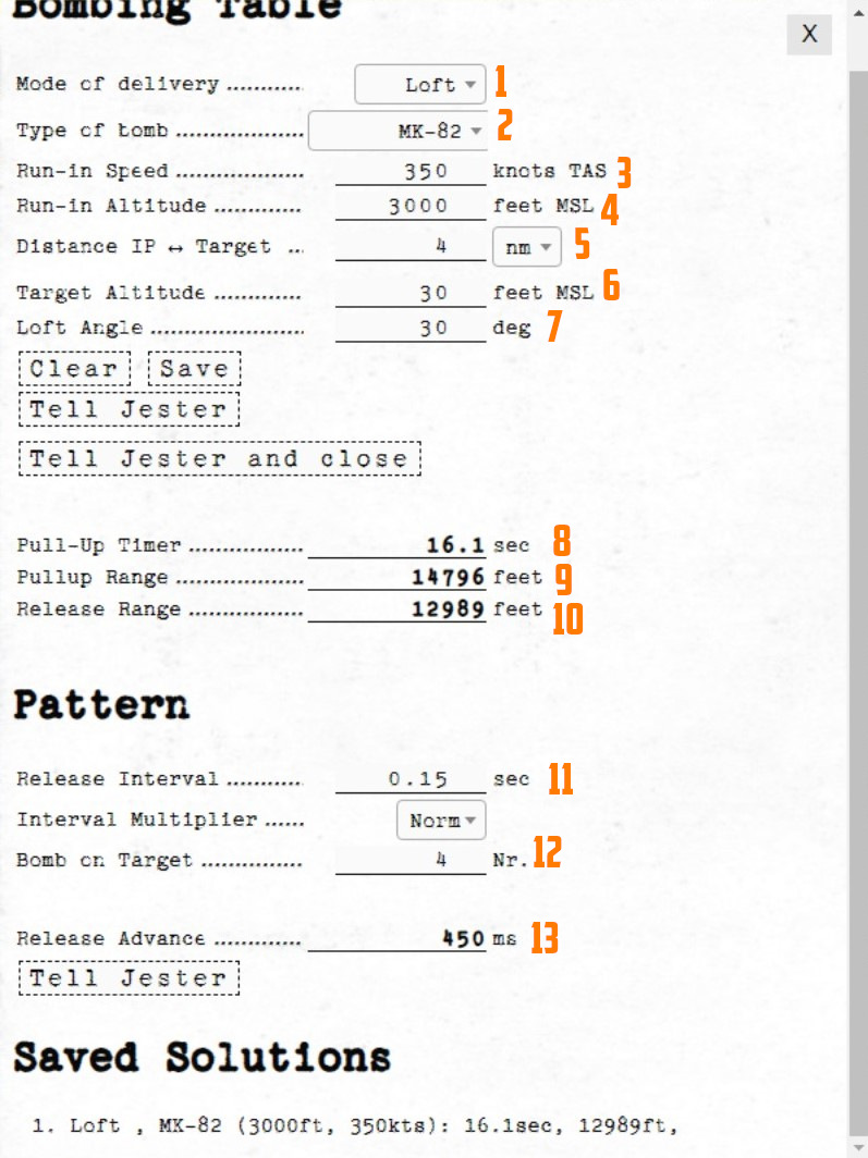
Now that we have all needed values from the map we will put those in the bombing calculator.
(
(
(
(
(
(
(
(
(
(
(
(
(
Setup
Now the WSO can put in the Loft Angle at the release angle, the pull-up timer at the bombing timers and the release advance in the release advance in the WRCS.
Execution
Now you only need to fly the maneuver for the Loft delivery as precise as possible to make sure you hit the target right. The more precise you fly, the more precise your bombing run will be.
Grease Pencil
Both crew members can use a grease pencil to draw on the side of their canopy.
The interface can be opened by clicking on the corresponding spot on the right front side of the canopy.
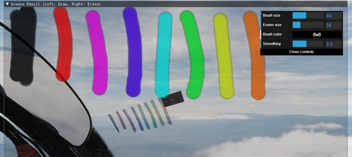
Holding down left click allows drawing, while right click will use the eraser.
After closing the window by clicking on the canopy spot again, the results are rendered on the canopy.

💡 Due to engine limitations, the image is not synchronized in multiplayer and is not visible from external view.
Spotting Circle
To aid in crew coordination, during startup and planning, a commonly employed technique is to select a static object at distance, such as a building, vehicle or tree, and drawing a circle around it.
The circle drawn by the Pilot and the WSO will now roughly point in the same direction and, once in air, can be used to enhance coordination.
For example, if the Pilot spots a target, they can tell the WSO:
"There is a target 100m right to the circle."
The WSO can now use his circle marker to locate the right spot.
Virtual Browser
To enhance in-flight studies of the aircraft or simply to overcome some downtime, a virtual browser can be opened (by default RCTRL+V).
The browser enables users to
- watch tutorial videos,
- read documentation provided by third parties,
- listen to a music playlist while flying,
- or also playing some browser games and much more.
The UI is embedded in-game, can be resized and moved around. Buttons on the top left corner allow for quick navigation.
💡 To allow free browsing select Full for the Special Option HB UI Domain Access.
Session
Session data is memorized and saved locally in a folder like
C:\Users\John Doe\Saved Games\DCS_F4E\cache\
Clearing this folder will reset all browser preferences and settings.
If required, sound level of the browser can be controlled via the volume mixer provided by Windows through the HeatblurUi.exe entry.
Recorders
The aircraft is equipped with multiple recording devices, such as the AVTR or the Gun Camera.
They are capable of recording in-game footage, which is accessible outside of the game in the Saved Games folder. A possible path might for example look like:
C:\Users\John Doe\Saved Games\DCS_F4E\recorders\
Airborne Video Tape Recorder
The AVTR records footage into folder
C:\Users\John Doe\Saved Games\DCS_F4E\recorders\avtr\
as PNG files every three seconds, if activated. Each cassette can record up to 20 minutes of footage and, if unthreaded, will overwrite previously recorded footage.
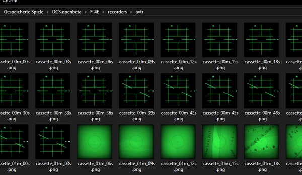
💡 This limits the footage to 400 files, each having a size between 50 KB (radar) to 400 KB (TV), totalling to 160 MB.
See 2.1.10.3 AVTR System and 2.2.2 AVTR Control for details on how to operate the device.
Tape Player
Although not present in the real Phantom, our aircraft is equipped with a Tape Player to listen and rock to great tunes in-flight!
Therefore, the Airborne Video Tape Recorder doubles as recorder and, if inserting a special music cassette, as music player.
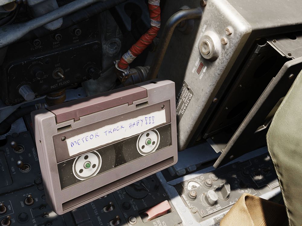
💡 The songs can also be found in highest quality in
<DCS Install Folder>\Mods\aircraft\F-4E\Music\Of Ghosts and Thunder (Meteor F-4 OST).
Controls
The AVTR and most of its controls are to the right of the pilot seat, see 2.1.10.3 AVTR System for details. Status lights and its mode switch can be found on the main panel in the WSO cockpit, see 2.2.2 AVTR Control.
💡 Jester can set the mode from his UI under "Systems > AVTR Recorder".
To swap the cassettes, the AVTR first has to be turned off by setting its mode to OFF. Then, the EJECT button can be pressed to open the cassette holder.
Once the cassette is out, it can be swapped by clicking on it. Insert the cassette back by left clicking the holder.
With the music tape loaded, songs can be played by setting the mode switch to RECORD. The RECORDER ON lamp next to the pilots left knee indicates the status and rotating it will adjust the volume.
The AVTR shows the soundtrack currently playing on its display for Elapsed Time,
e.g. M01 for the first track. Tracks can be skipped by using either the
UNTHREAD button or by clicking on the RCD/EOT lamp in the WSO cockpit.
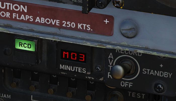
If the tape has finished playing all songs, the EOT lamp illuminates and explicitly commanding the next track will start the first track again.
Custom Songs
The Tape Player automatically fetches any song found in
<DCS Install Folder>\Mods\aircraft\F-4E\Sounds\TapePlayer
and plays them in alphabetical order.
Note that it is necessary for DCS that each song is also set up as a SDEF file in
<DCS Install Folder>\Mods\aircraft\F-4E\Sounds\sdef\TapePlayer
To add your own songs, simply put them into the above folder and create the corresponding SDEF file. Make sure to restart DCS, as sounds are loaded during start of the game.
Character
Customization
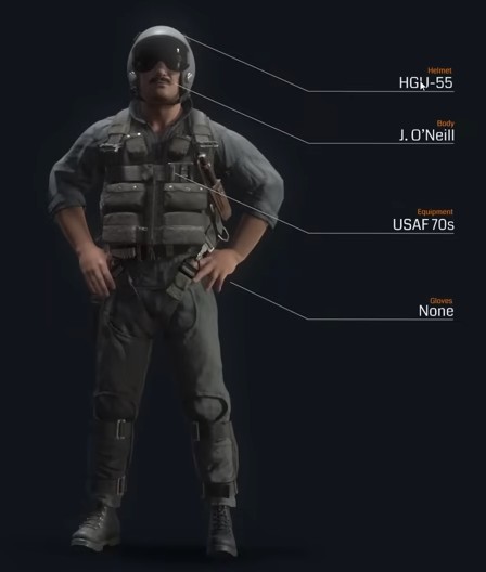
The pilot and WSO character can be customized through an in-game menu, for example selecting one of the many available helmets.
🚧 Character customization will be made available later during Early-Access.
Selfie Mode
To enable great screenshots, a special Selfie Mode can be entered via an assignable special bind.
In this mode, the character model is rendered even though the player is currently in First-Person-View (F1).
The camera can then be moved for example to the front via standard DCS controls:
- RCtrl + RShift + 8 (Numpad): Move up
- RCtrl + RShift + 2 (Numpad): Move down
- RCtrl + RShift + 4 (Numpad): Move left
- RCtrl + RShift + 6 (Numpad): Move right
- RCtrl + RShift + / (Numpad): Move forward
- RCtrl + RShift + * (Numpad): Move aft
The view can be turned back to face the pilot by using LAlt + C and then using the mouse.
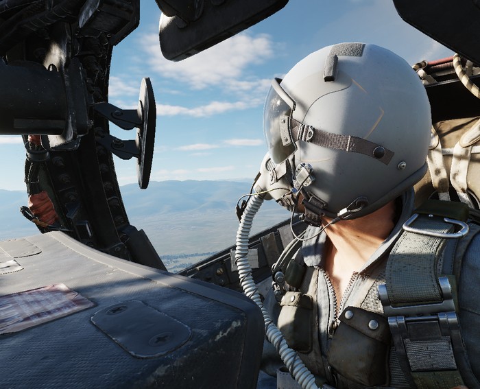
Additionally, another special bind exists to freeze the character model movement.
Mission Editor
The F-4 has several special options selectable in the Mission Editor.
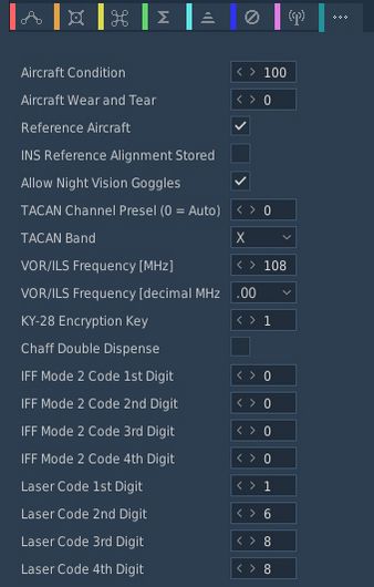
Condition and Wear
"And I'll tell you what, since Cal's on it, it's only flown on approved cross-countries and drill weekends. Mint condition, folks, no over-Gs."
All components of the aircraft simulate wear individually, yielding a unique experience on each spawn, but also based on how the F-4 is flown.
It is generally differentiated between Condition and the Wear and Tear, both are dynamic at spawn and can be influenced throughout a mission by various factors such as forces, temperature and also combat damage.
The aircraft has thousands of components that are subject to this system. One concrete example would be the speed of the Pave Spike Targeting Pod elevation gimbal motor. Under perfect condition, it is supposed to have a speed of 60 degrees per second. However, a factory generally can not ensure this to always be the case and accepts a variance, for example it must be within 1% error.
Mathematically, variance is simulated as normal distribution, consisting of the parameters
- μ (Mu, mean) - the value it would have under perfect condition
- σ (Sigma) - the variance of the value
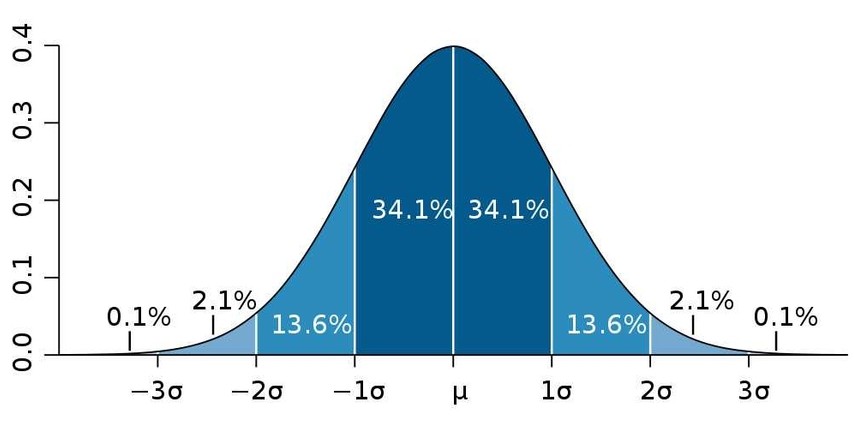
Around 70% of times the value will be within one unit of σ, in 95% of cases it will be within 2 units of σ. Extreme cases above 3 units of σ are possible, but very rare.
Said motor has for example a σ value of 3% around 60 degrees per second, meaning that the vast majority of targeting pods will be produced with a motor capable of moving the elevation gimbal between 58 and 62 degrees per second.
💡 Variance goes in both directions, your Phantom can also be faster than it is supposed to be.
Aircraft Condition
An aircraft's condition generally refers to its factory and production quality. For example, during war times a factory might run out of supplies and reduce their acceptance criteria during production, generally increasing variance in individual component performance.
Mission designers can control this aspect with the Aircraft Condition slider, indicating quality from 0% (poor quality) to 100% (high quality).
For the Pave Spike motor this means that, when set to 0%, its speed variance σ will increase from 3% to 8%, causing majority of pods to be produced with a speed between 55 and 65 degrees per second instead.
Aircraft condition will always still be within limits that a manufacturer might find reasonably acceptable. The aircraft is always still fully functional and operational.
Aircraft Wear and Tear
Additionally to production quality, components can degrade during service based on time since the last overhaul, external factors like temperature and weather, aggressive flying involving a lot of forces on the airframe, as well as combat damage.
Mission designers can control this aspect with the Aircraft Wear and Tear slider, indicating wear from 0% (no wear) to 100% (a lot of wear), or even beyond that. For an aircraft that was just repaired and came fresh out of service, 0% is appropriate. 100% refers to the latest point at which an aircraft would reasonably be send back for maintenance, as it starts being less effective in practice. Values beyond, such as 500%, can be used to represent scenarios in which pilots are forced to fly an aircraft that operates exceptionally below its expected performance level. It is still somewhat usable, nothing is straight out broken, but components just do not behave within acceptable parameters anymore.
💡 Values beyond 100% cannot be set in the Mission Editor, but are achievable in-flight.
For the Pave Spike motor this means that, when set to 100% wear, its speed variance σ will additionally increase by 20%. Assuming a good initial starting condition, the motor will at that point likely operate between 45 and 75 degrees per second.
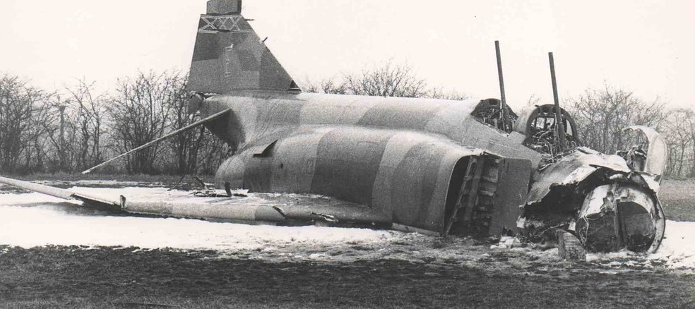
Reference Aircraft
The variance system at initial spawn can be turned off with this checkbox, if desired. Components will then start with their mean value μ, without any variance.
That is, with the option checked the setting for condition, as well as wear and tear are ignored and disabled. The aircraft will spawn with all properties set exactly as specified by the manufacturer and according to documentation, without any variance.
This is especially interesting for competitions, where both sides should start with the same conditions for fairness. Or when performing tests and computing performance charts, where the aircraft should always start with the exact same values.
💡 Even the reference aircraft is still subject to wear and tear during flight. In a competition, if you pull high Gs, your aircraft's component properties will deviate from your opponents.
INS Reference Alignment Stored
This checkbox allows significant reduction of the time needed for a proper INS alignment during cold-start.
Therefore, the ground crew would previously have started the aircraft and executed a full alignment, then shut it down again, while memorizing parts of the alignment data.
See the INS section for details on how to execute a stored alignment.
Allow Night Vision Goggles
Although F-4E crews never actually operated with NVGs, this option allows mission designers to create modern or fictional scenarios where Phantom crews might have access to such devices.
TACAN Options
Allows to set the TACAN channel and band set when spawning initially.
VOR/ILS Options
Allows to set the VOR/ILS frequency when spawning initially.
KY-28 Encryption Key
Allows to set the encryption key used by the KY-28 communication encryption system.
This setting is especially important when using tools such as ED-VOIP or SRS that simulate encryption while using the radio equipment.
See the KY-28 System for details.
Chaff Double Dispense
An option available to the ground-crew on the AN/ALE-40 countermeasure dispensers.
When selected, each signal to release chaff instead releases chaff on both sides simultaneously.
See the AN/ALE-40 system for details.
IFF Mode 2 Options
Allows to preselect a Mode 2 code for the IFF system.
Laser Options
Allows to preselect a laser code for the targeting pod and laser-guided weapons.
Radio Options
The editor allows to preset all 18 COMM and 20 AUX channels of the UHF radio:
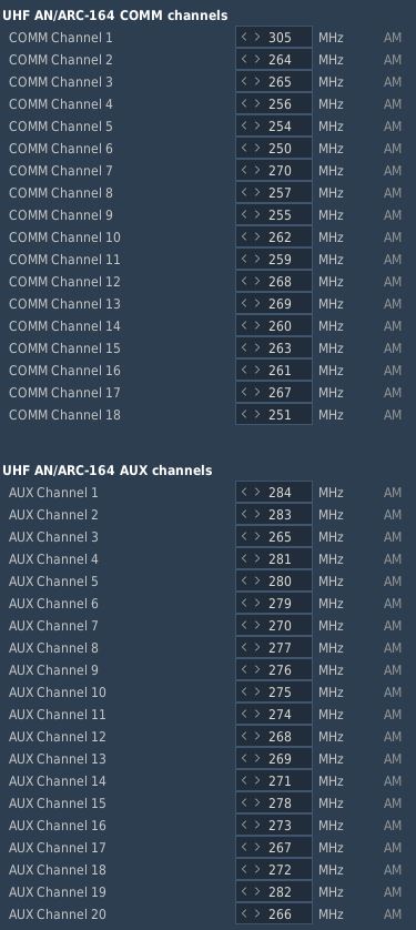
It is possible to set up a station in the Mission Editor for use in ADF navigation. To do this, a unit, such as a ground station, needs to be placed on the map. This unit should then execute a command to tune into the desired AM frequency (Perform Command > Set Frequency). Finally, the unit must transmit a message continuously throughout the mission, which requires setting the message to loop (Perform Command > Transmit Message).
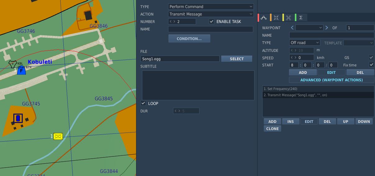
Also, radio frequency parameters to read currently active UHF Radio frequencies are provided for mission triggers:
| Parameter | Description |
|---|---|
COMM_FREQ | Comm frequency in MHz |
AUX_FREQ | Aux frequency in MHz |

Training Missions
Lessons
These missions, we like to call them "lessons", have been designed in such a way that, as a beginner, everything important that you need for a successful start with your new F-4E Phantom II is explained.
Goals
The stated goal of these lessons is that after completing them once or several times, you can say: "Hey, I think I now know how this thing works (again)". You can use the lessons as "initial training" or as so-called "recurrent training". Whenever you haven't flown for a long time and need a refresher. By the way: We recommend a refresher every 90 days at least ...
Please note that the lessons require a certain level of knowledge and basic flying skills. In the lessons we don't explain flying as such, but rather the aircraft, its systems and their usage, and the behavior. The lessons may therefore be understood as a kind of "interactive type training in the cockpit seat" and not as "basic flying training".
Your way through
Due to the design, systems and age of the jet, it has many pecularities. Precise application of system knowledge in daily duty on this wonderful aircraft is the key to success. With the F-4E Phantom II you will be challenged in so many ways. So be ready! We leave it up to you whether you want to get in the air immediately without studying the manual, or whether you want to read upon it before your first flight ...
Decide for yourself!
If you want to fly immediately, the training lessons will provide you with enough knowledge to successfully complete these flights. You can even study this section or other parts of the manual during your flights; this is another innovation in the DCS F-4E Phantom II. The lessons can be paused at any time if necessary. Of course, you are welcome to practice multi-tasking and fly at the same time as studying the manual; that's not explicitly forbidden! Learning by doing is the basic strategy for the training lessons, but you will be required to read through the manual and carefully study the systems if you want to become a real pro.
Procedures
We have depicted the most important "normal procedures" of the aircraft and have based the lessons very much on reality. These procedures should also be based as closely as possible on the real procedures, although we were aware that it wouldn't be possible to implement everything in the simulation. Think, for example, of the ejection seat harness, the oxygen mask and its test, the transponder, the IFF system, or similar systems. Some steps are left out because they are already set correctly after spawning the aircraft and to really speed up the lesson to get you in the air; of course you may check them as well.
Therefore, not all procedures are depicted as can be found in real aircraft manuals; some of them had to be changed, shortened, or omitted entirely. Nevertheless, for example, we simulated putting on the helmet (including sun protection visor and sun glasses), an immersive innovation in DCS.
Our way
We thought a lot about how best to explain the operation of such a complex aircraft with training missions. Where do you start, where do you end? How detailed should it be so that a "nerd" doesn't miss anything, how superficial can it be so that a "leisure gamer" doesn't lose interest? How tight are the checks whether the player is adhering to the procedures and the planned flight route? A basic idea at Heatblur has always been to get players "in the air" as quickly as possible, without them having to spend hours watching introductory videos or studying thick books. All of this caused us a lot of headaches...
In any case, we spared no expense, effort and discussions to serve both types of players more or less "equally". As you can imagine, such a project is not entirely trivial, and you have to make a lot of compromises when designing the lessons. Sometimes, you have to tell hardliners: "Hey, this might be too difficult for the players and not really relevant to the simulation, eventhough it would be extra cool!" You have to convince other team members to do things they personally don't like: Hey, that's exactly what the players need, but a little different please!
Fortunately, we had professional help from SME's (real former Phantom pilots and weapons systems officer and even instructors). These guys helped us with so many decisions, and spiced the product with their knowledge and experience. Conversely, they slapped us on the wrist if we left out something they thought was important.
In a complex development process that such a high-quality DCS module requires, there are many obstacles and limitations, but also many opportunities and possibilities. That's why we made it a point right from the start to present the handling of the aircraft's systems as comprehensively as possible.
We hope you like what you have in hands now!
Lessons Overview
This section is limited to the description of the first 4 lessons:
- Lesson 01 - Startup
- Lesson 02 - Taxi
- Lesson 03 - Normal Takeoff
- Lesson 04 - Visual approach
General Tips and Tricks
It rarely happens that you get stuck in a procedure, or you don't know exactly what to do next.
Here are some general tips & tricks as created by testers during the testing phase:
- For lessons starting on the ground, the noise might be very loud. You have three options:
- Wait until the other jets have taken off before beginning with the lesson.
- You are allowed to close the canopy whenever you need to (default binding is LCTRL+C), despite the F-4 usually closes it very lately
- Adjust the audio volume of DCS to suit the autio hardware you are using.
- If you have troubles with a very dark cockpit, a few things can be done:
- Use the internal cockpit illumination on the COCKPIT LIGHTS panel (right side):
- The CONSOLE OFF/BRT knob
- The INSTR PANEL knob
- The CONSOLE FLOOD light switch
- The INST FLOOD light switch
- Use the internal cockpit illumination on the COCKPIT LIGHTS panel (right side):
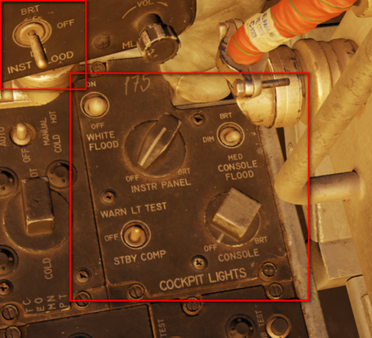
- Set the SYSTEM option "Cockpit Global Illumination" to ON
- Set the SYSTEM option "Gamma" to 2.0 or higher values.
Emergencies
There are situations in which the triggers of a lesson no longer work properly for some unknown reason. Fortunately, this only happens very rarely! This usually results in the highlights (the yellow helper boxes) no longer being shown or hidden correctly, or the logic circuits no longer reacting correctly to events in the simulation. We experienced this ourselves during the testing phase and would like to at least inform you about it here and now.
The influence of the time acceleration function on the stability of the lessons is not documented, but to be on the safe side we advise against using the time acceleration function.
If you got stuck in a lesson, you should take the following actions:
-
Stay calm! The two most important pilot rules apply:
- Aviate, navigate, communicate.
- Don't crash, and above all: don't break anything!
-
Check whether everything in the aircraft is actually set up as required according to the checklist/procedure. If necessary, go up the list a few steps and again check each step individually, starting from the top by asking yourself: What is written in the book? > How did I set it up?
-
If that doesn't help: Jump back one, or even more steps (how to do this is explained above)
-
If that doesn't help either: Jump back to the beginning of the procedure (how to do this is explained above)
-
If all that doesn't help:
- Quit the mission and save the DEBRIEFING (log-file) and the TRACK (trk-file) in the debriefing screen
- If you suspect a bug, please open a new ticker in the DCS forum > Heatblur Simulations > Phantom area using this link: https://forum.dcs.world/forum/919-dcs-f-4-phantom/. Please add as much information as possible in order to help us finding a possible issue. Thank you for your support!
- In any case, we recommend to restart DCS and load the mission again. Sorry for that!
Lesson 01 - Startup
Lesson 01 - Kobuleti airfield
The airfield has a picturesque location between the mountains to the south and the Black Sea to the west. Here is a photo of the airfield, taken a month ago from a helicopter, looking S- W.
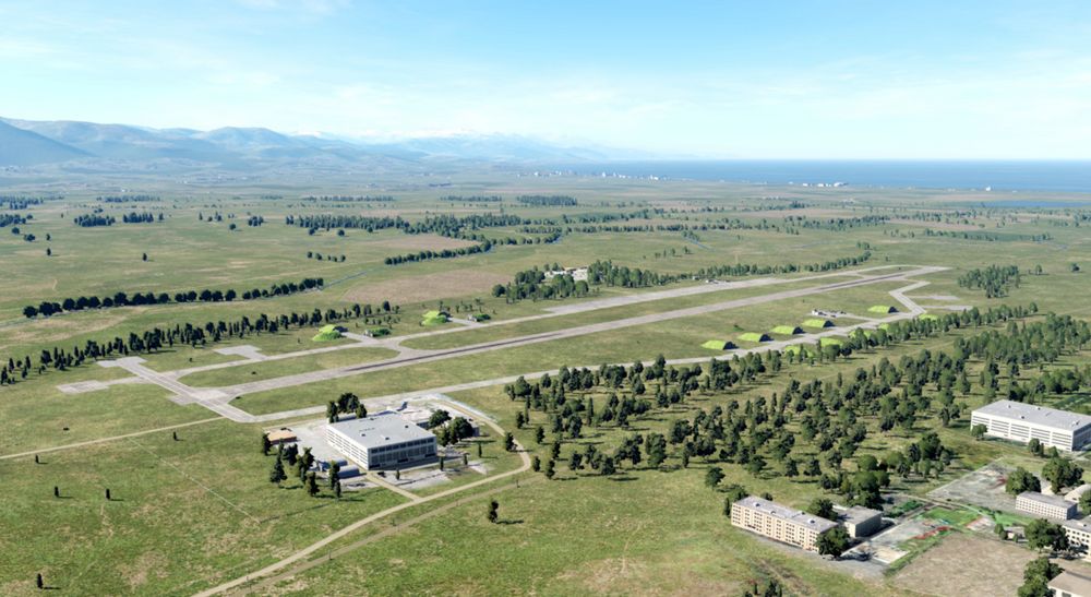
The entire F-4E Phantom II training for your year (July 1995 syllabus) will be held in Kobuleti. The choice fell on an airfield in the Caucasus region for understandable reasons, as this map is delivered with DCS as standard. The designated training areas in the south of Georgia (designated as "Training Area W" and "Training Area E") offer a sufficiently large playground for training, including supersonic flights.
Lesson 01 - Weather
The weather has been very bad in the last few days. A persistent Black Sea depression had brought a lot of rain. However, stabilization occurred last night and morning. Dry air mass flows in from the east. The mid-level cloud layer is expected to break up. The weather forecast predicts that the clouds will no longer be a problem in about an hour and the temperature will rise quickly due to strong sunshine. However, ground-level haze is still to be expected as the ground has stored a lot of moisture and heavy evaporation from the sun is to be expected.

Lesson 01 - Slots
Your fellow pilots will begin their flights immediately, your flight a little later. The airfield is a very noisy environment, so wait until the jets currently positioned on the runway have taken off before beginning with the lesson. Then the noise level should be somewhat tolerable... hopefully at least.
Currently registered sorties for this afternoon:
- #1 Dodge 41 (AI, already in the air)
- #2 Dodge 31 (AI, already in the air)
- #3 Dodge 21 & 22 (AI, at the start)
- #4 Dodge 11 (you, at parking position #25)
All Dodge flights complete familiarization and training flights at the airfield.
Lesson 01 - Aircraft
Your aircraft is "cold & dark" on the ramp #25, the nose is pointed towards the runway, and is prepared and fully fueled. The Dash-60 ground power unit is already in place left of your jet.
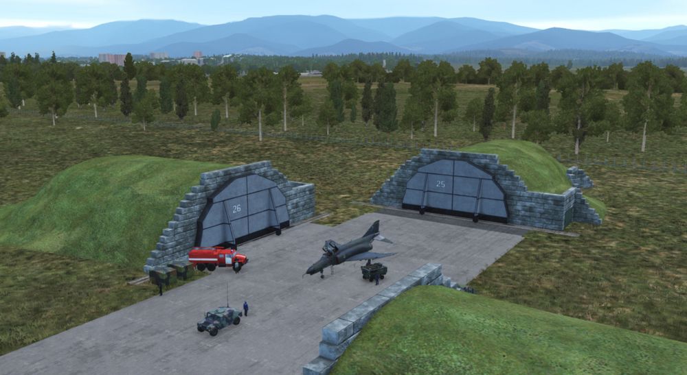
The technician responsible for the aircraft, also called the "crew chief", is already in front of your aircraft and waiting to support you. You can communicate with him using the Jester menu > CREW CHIEF.
By the way, his assistant is standing by on your left side, next to the Dash-60 ground power unit.
You've just sat down in the ejection seat and are starting to check the cockpit. You may be saying to yourself "Damn, I'm blown away by everything I see, but I guess I don't know what I'm doing...".
Don't worry, your instructor, who is also your WSO for today's flight, will guide you through the lesson!
Lesson 01 - Audio & text
Your instructor speaks from the back seat, always listen carefully. Assume that everything he says is important. As an aid, all of the text he speaks is displayed at the top right of the screen. If you don't notice or understand something, you can always read it above. The text remains visible on the screen for a maximum of 1000 seconds until it either disappears or is replaced by new text.
Note that whenever you missed one of the text messages, you can access the message log by pressing the key "Escape" and then selecting MESSAGES HISTORY and read after.
Lesson 01 - Tasks & steps
The lessons are divided into tasks, which are based on the names of the procedures. These tasks are divided into individual steps, whereby the steps go hand in hand with the individual items in the procedure. The tasks for this lesson are:
- Task 1: Check the aircraft and essential switches before applying external power.
- Task 2: Perform the internal inspection of the aircraft.
- Task 3: Prepare the aircraft for engine start.
- Task 4: Start the engines.
Here are some special tips for lesson 01
- Task 4: Let the instructor speak to the end of each instruction, there is enough time for the actions to be carried out.
- Task 4 > Step 4b: Be careful when opening the fuel, this should not be done before 10% RPM! If you see the EGT rising above 700°C, immediately cut off the fuel by moving the throttle lever to the "OFF" position. Note: engine parameters may vary slightly depending on the environmental conditions. Only the EGT value is to be monitored very closely!
Lesson 02 - Taxi
Lesson 02 - Weather
The weather changes slowly but noticeably. The clouds start breaking up, and the forcast regarding the ground-level haze was correct. Wind speed and direction haven't changed so far.

Lesson 02 - Slots
Slots haven't changed.
- #1 Dodge 41 (AI, already on ground, refuelling)
- #2 Dodge 31 (AI, already on ground, refuelling)
- #3 Dodge 21 & 22 (AI, at the start)
- #4 Dodge 11 (you, at parking position #25)
All Dodge flights complete familiarization and training flights at the airfield.
Lesson 02 - Aircraft
Your aircraft is already "hot on the ramp #25" with both engines running, the nose is pointed towards the runway. All aircraft systems are set to the positions in which you left in the previous lesson. The Dash-60 ground power unit is already removed.
The "crew chief" has changed his position to forward right of your aircraft and is waiting to support you.
His assistant is standing by on your forward left side.
Lesson 02 - Audio & text
Your instructor speaks from the back seat, always listen carefully. Assume that everything he says is important. As an aid, all of the text he speaks is displayed at the top right of the screen. If you don't notice or understand something, you can always read it above. The text remains visible on the screen for a maximum of 1000 seconds until it either disappears or is replaced by new text.
Note that whenever you missed one of the text messages, you can access the message log by pressing the key "Escape" and then selecting MESSAGES HISTORY and read after.
Lesson 02 - Tasks & steps
The lessons are divided into tasks, which are based on the names of the procedures. These tasks are divided into individual steps, whereby the steps go hand in hand with the individual items in the procedure. The tasks for this lesson are:
-
Task 1: Check the aircraft before moving on own power.
-
Task 2: Taxi to holding point RWY 07.
Lesson 02 - Tips & tricks
Here are some special tips for lesson 02:
-
Task 1 > Step 7: The flight controls check can be omitted in case it becomes too difficult. Use the FIRE TEST BUTTON on the instrument panel before or during performing this check to skip it. The reason for this is that for this check a few things have to be done in parallel:
- Listening to our instructor
- Performing the inputs on the flight control system (movements and button/switch presses/settings)
- Listening to the confirmation given by the crew chief
- Pressing "Spacebar" after receiving the crew chief's confirmation
-
Task 1 > Step 7f & 7h: The crew chief will not respond when you set the rudder to the neutral position.
-
Task 2 > Introduction: Observe that the audio containing the taxi clearance by ATC is played through your UHF radio. Therefore, if you turn off or tune down the volume of the radio, or route the audio signal to some other audio device tuned down in volume, you might not hear the call correctly. In any way, the spoken text can be read on the upper right corner of the screen, and the lesson continues normally.
-
Task 2 > Step 1a) Use the power levers very gently! Once the aircraft started rolling, pull back the power levers to idle and carefully control the taxi speed using minimum power together with the wheel brakes.
Lesson 03 - Normal Takeoff
Lesson 03 - Weather

The weather is changing noticeably with every minute. The clouds continue breaking up, and the ground-level haze is still there. Wind speed and direction haven't changed so far.
Lesson 03 - Slots
Slots haven't changed.
- #1 Dodge 41 (AI, already on ground)
- #2 Dodge 31 (AI, already on ground)
- #3 Dodge 21 & 22 (AI, already on ground)
- #4 Dodge 11 (you, at the holding point for runway 07)
All Dodge flights complete familiarization and training flights at the airfield.
Lesson 03 - Aircraft
Your aircraft is already "hot on the holding point for runway 07" with both engines running, the nose is pointed towards the runway. All aircraft systems are set to the positions in which you left in the previous lesson.
Lesson 03 - Audio & text
Your instructor speaks from the back seat, always listen carefully. Assume that everything he says is important. As an aid, all of the text he speaks is displayed at the top right of the screen. If you don't notice or understand something, you can always read it above. The text remains visible on the screen for a maximum of 1000 seconds until it either disappears or is replaced by new text.
Note that whenever you missed one of the text messages, you can access the message log by pressing the key "Escape" and then selecting MESSAGES HISTORY and read after.
Lesson 03 - Tasks & steps
The lessons are divided into tasks, which are based on the names of the procedures. These tasks are divided into individual steps, whereby the steps go hand in hand with the individual items in the procedure. The tasks for this lesson are:
- Task 1: Check aircraft while being positioned at the holding point for RWY 07.
- Task 2: Line-up the aircraft on RWY 07
- Task 3: Check essential aircraft systems while being lined up on RWY 07
- Task 4: Perform a normal take-off (slats & flaps "out" & "down") on RWY 07
- Task 5: Perform a normal climb at 350kts or M0.9 (whichever is reached first), by following turnpoints 1, 2 and 3.
- Task 6: Perform cruise checks.
Lesson 03 - Tips & tricks
Here are some special tips for lesson 03:
-
Task 1 > Steps 4a - 4e: The flight controls check only requires to check if the stick is moving freely (at least 50% of the stick deflection must be made). You can also check the rudder, but this is not required by that step.
-
Task 1 > Step 10: Having the MASTER CAUTION alert active indicates something is or at least was wrong. So reset it, then check if it stays out.
-
Task 2 > Step 1: Observe that the audio containing the line-up clearance by ATC is played through your UHF radio. Therefore, if you turn off or tune down the volume of the radio, or route the audio signals to some other audio device tuned down in volume, you might not hear the call correctly. In any way, the spoken text can be read on the upper right corner of the screen, and the lesson continues.
-
Task 4 > Introduction Observe that the audio containing the take-off clearance by ATC is played through your UHF radio. Therefore, if you turn off or tune down the volume of the radio, or route the audio signals to some other audio device tuned down in volume, you might not hear the call correctly. In any way, the spoken text can be read on the upper right corner of the screen, and the lesson continues.
-
Task 4 > Step 5: For beginners, we recommend to perform the first take-off without afterburner (just MIL power, which means 100% rpm without afterburner), despite we know that taking off with afterburner is a ton of fun. The reason behind is, that you will then be able to hear all call-outs of your instructor, because the time needed for the take-off is long enough. Whenever you think you manage all steps by heart that are necessary for a safe take-off without any instructions, go for a take-off with afterburner. Please don't tell our SME's that this text exists at all, and never tell someone that you have followed the recommendation ...
-
Take-off: Before taking off, go through the takeoff procedure. You need to remember the items by heart:
- No NGS after 70 knots
- Full aft STICK by 80 knots
- Hold 10 to 12° NOSE UP
- Raise the GEAR & FLAPS as soon as airborne
- TRIM as needed
-
Task 4 > Step 8: In DCS, with the current wind situation (no cross wind component), it is really not necessary to use the nose gear steering. You will only be reminded by the instructor in case you use the nose gear steering above 70 knots.
-
Task 4 > Step 11: Pitch trim is best done in a number of quick pulses instead of one long press to avoid over- trimming.
-
Task 4 > Steps 13: Make sure to have flaps retracted before reaching 250 knots, but there is a certain safety buffer and they should not be damaged at exactly 250 knots.
-
Task 5 > Step 1: Make sure to fly a heading of about 064° and climb after lift-off. Make sure to fly at an airspeed of not more than 350 knots. Fly a shallow climb when using no afterburner (about 10° pitch angle). Fly a steep climb when using afterburner (about 30° pitch angle).
-
After reaching a certain altitude and airspeed with gear and flaps up, the lesson is accomplished. You may continue the climb following the route which is commanded by your instructor. If you got "lost in space", open up the F-10 map, click on your aircraft, and observe the planned flightroute; you may then follow it more easily.
-
Task 6 > Step 1d: There is currently no way of comparing the values on both altimeters. This step was kept in the procedure just in case you need it when operating with a real WSO in the rear seat.
Lesson 04 - Visual approach
Lesson 04 - Weather
The weather has become pretty nice. The clouds have disappeared more or less, and the ground-level haze is less visible due to the quickly rising temperature. Wind speed and direction still haven't changed so far.

Lesson 04 - Slots
Slots haven't changed.
- #1 Dodge 41 (AI, already on ground)
- #2 Dodge 31 (AI, already on ground)
- #3 Dodge 21 & 22 (AI, already on ground)
- #4 Dodge 11 (you, in-flight inbound turnpoint 7)
All Dodge flights complete familiarization and training flights at the airfield.
Lesson 04 - Aircraft
Your aircraft is already "in flight" inbound turnpoint 7 at 22,000ft altitude at Mach 0.7. All systems are set in a way as they would be after a typical air-to-air training, thus it will be required to prepare the aircraft for the upcoming approach and landing.

Lesson 04 - Audio & text
Your instructor speaks from the back seat, always listen carefully. Assume that everything he says is important. As an aid, all of the text he speaks is displayed at the top right of the screen. If you don't notice or understand something, you can always read it above. The text remains visible on the screen for a maximum of 1000 seconds until it either disappears or is replaced by new text.
Note that whenever you missed one of the text messages, you can access the message log by pressing the key "Escape" and then selecting MESSAGES HISTORY and read after.
Lesson 04 - Tasks & steps
The lessons are divided into tasks, which are based on the names of the procedures. These tasks are divided into individual steps, whereby the steps go hand in hand with the individual items in the procedure.
The tasks for this lesson are:
- Task 1: Check aircraft for landing while in cruise flight.
- Task 2: Prepare the aircraft for landing while in the downwind RWY 07.
- Task 3: Land the aircraft on RWY 07.
- Task 4: Secure the aircraft while taxiing back to the parking position PRK 25.
Lesson 04 - Tips & tricks
Here are some special tips for lesson 04:
- Trim the jet: Pitch trim is best done in a number of quick pulses instead of one long press to avoid over-trimming.
- Autopilot: Use the autopilot modes "attitude hold" and "altitude hold" whenever you think you need your hands free. The system is a great assistant, so use it!
- DME distances: DME distance information is shown on the lower left corner of the HSI.
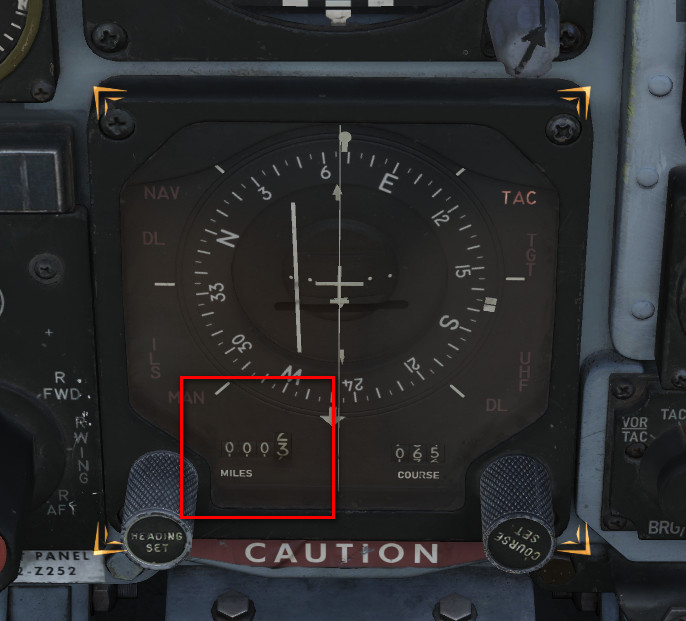
- HSI course settings: The course setting can be changed with the COURSE SET KNOB on the lower right corner of the HSI:
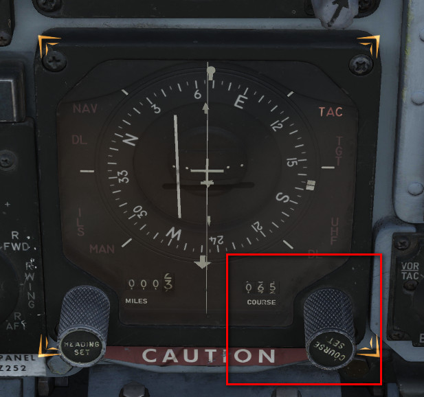
- Task 1 > Step 4: If you can't reach the COMM Antenna Select Switch, move the throttles back for a moment.
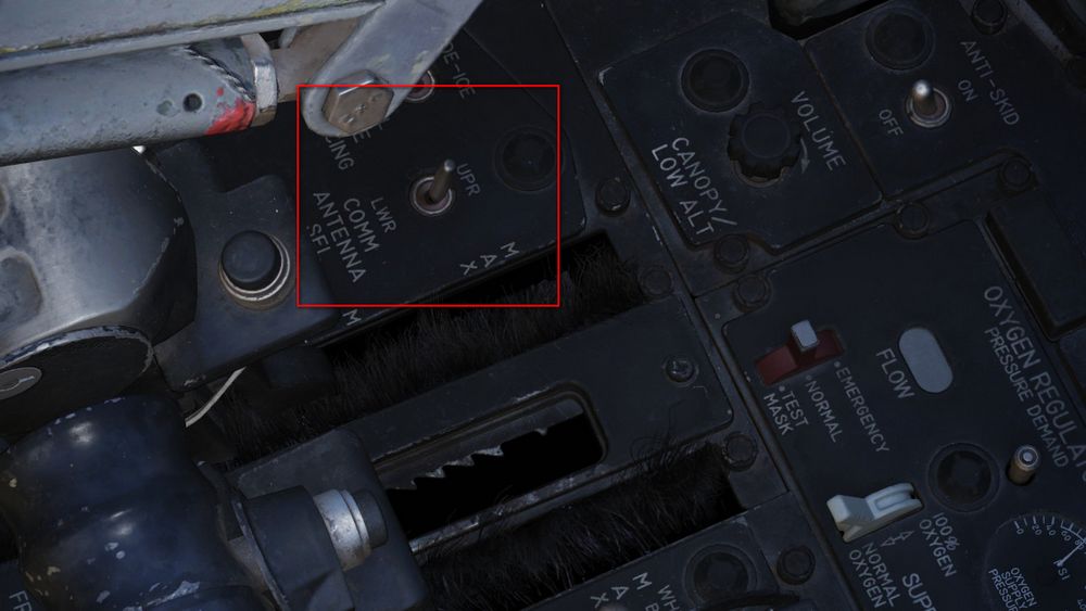
- Task 1 > Step 8: The transition altitude in this particular region is 4,000m (13,120 ft), and the transition level is flight level 140 (FL140, which is 14,000 feet). When you descend through 14,000 feet, you have to set your altimeter to the value of the local QNH (which today is 29.84 in/HG). It's no big deal if you forget about that, it is not relevant for the outcome of the lesson.
- PENETRATION / DESCENT: Follow the instructions as good as possible. You may engage the attitude hold autopilot during descent and focus on airspeed and power management. Don't forget to set the QNH once passing the transition level (in this case 14,000 feet).
- PENETRATION / TURN: Fly a shallow left turn. If you have already reached 2,500 feet altitude, good. If you are still higher, continue descending during the left turn until reaching 2500 feet. Keep an eye on your sink rate. Fly smoothly, and don't work hard on the stick. Intercept radial 064 as good as you can in order to align on the runway heading. Treat her like a lady, and think ahead! Use the F-10 map if you got lost in space. Don't rush into Batumi airspace. Landing permission is already given. You are the last flight approaching the airfield for the next two hours.
- Task 2: Remember these five items by heart: GEAR / FLAPS / HYDRAULIC PRESSURE / WARNING LIGHTS / ANTI SKID
- Task 3: If you fly correct airspeeds, all instructions can be heard until the end. If you rush, the timeline becomes compressed and the sequence of events then may become overwhelming. During the approach continuously cross check Pitch / Power / Trim. Look out for the runway, adjust your heading with slight roll maneuvers if necessary. Rise the seat in case you have troubles seeing the runway at higher angles of attack. Fly gently, follow the instructions, and think ahead!
- Go-around: In case you have the slightest doubt that you cannot manage a safe landing: GO AROUND. Fly the missed approach procedure by entering a short left hand traffic pattern at 1500 feet at 250 knots. Take your time, be patient with yourself, don't rush and keep an eye on airspeed and altitude!
- Landing / flare: The aircraft was certified for carrier landings. If you don't flare before touchdown at a 2° to 3° approach path, you WILL slam the aircraft into the runway. This causes wear to the wheels and the landing gear legs, but nothing more. You may decide on your own if you want to flare just a bit to decrease the sink rate slightly. Sink rates above 3 to 4 m/s (600 to 700 ft/min) depending on weight, might damage the landing gear though.
- Landing / touchdown: Make sure to stay aligned with the centerline using rudder only. Prepare yourself to deploy the drag chute, which stabilizes the aircraft during the landing roll. Taxi to the end of the runway and then leave it to the right side!
- Taxi: Follow the marshaller after leaving the runway. If you struggle performing the "After landing procedure " while taxiing, you may stop the aircraft on the taxi way for that. The car though will not stop. When finished with the procedure, continue taxiing to your initial parking position, nose pointed towards shelter "25", and stop there.
Modding
The Phantom encourages modding and allows the community to modify various parts of the simulation and experience.
Players can enjoy their creations either in Singleplayer or even in Multiplayer on servers that disabled their file-integrity-check.
💡 Let us know if you create a cool mod that you think should make its way into the module!
Jester
Jester is fully open to modding. Please see the Jester API for details.
Manual
This manual is open-source at GitHub.
If you found a typo or want to improve a section, please let us know or also feel free to contribute yourself directly at GitHub.
Integrated Websites
Several features of the aircraft make use of integrated websites, which are displayed in-game with a built-in web-browser.
The code for the websites can be found in the Mod-Folder, for example:
G:\DCS World OpenBeta\Mods\aircraft\F-4E\UI
The browser supports full HTML/CSS/JS and even allows loading external sites, such as visiting YouTube and watching some tutorials.
Feel free to enhance any of the existing sites, such as the Jester Wheel or Grease Pencil UI, if desired.
Explain-Me
To quickly find out what a switch does, the embedded manual allows holding a hotkey (M by default), then clicking any switch in the cockpit and the manual opens scrolled right to the spot explaining the corresponding switch.
On the technical side, this feature is setup in the lookup-table located in the Mod-Folder, for example:
G:\DCS World OpenBeta\Mods\aircraft\F-4E\Input\explain_table.csv
This file links pointer/connector names of the model to relative URLs of the manual.
# in explain_table.csv
PNT_Pull_Up_Light;cockpit.html#pull_up_system
PNT_FIRE_TEST_BUTTON;cockpit.html#fire_test_button
PNT_Marker_Beacon;cockpit.html#marker_beacon
PNT_VOR_Light;cockpit.html#vor_light
The URL, for example cockpit.html#fire_test_button, is then loaded in the Manual-Browser.
Jester
Jester is fully open to modding via a Lua-API. Any feature and functionality of Jester has been written by using this API.

The Jester AI primarily consists of:
- logic - written with the Lua-API
- user interface - embedded websites for the Wheel and Dialogs
- sounds - see Voice Files
💡 Let us know if you create a cool Jester mod that you think should make its way into the module!
Voice Files
Jesters entire library of phrases can be found in the Mod-Folder, for example:
G:\DCS World OpenBeta\Mods\aircraft\F-4E\Sounds\Jester
When editing sounds, it is necessary to restart DCS. Just reloading the mission is not enough for changes to take effect.
sdef
For DCS to understand the files, sound-definition-files (sdef) are located in:
G:\DCS World OpenBeta\Mods\aircraft\F-4E\Sounds\sdef\Jester
A sdef-file is a plain text-file that can be edited with any text-editor. Next to locating the actual sound file, it can define properties such as gain or fade-in/-out effects, as well as positioning the sound effect within the world when played.
wave = "Jester/Contacts/theresafriend4shipbraHI1"
inner_radius = 10
outer_radius = 100
position = {0.0, 0.0, 0.0}
gain = 2
streaming = false
preload = false
Variations
When placing multiple sound files with the same name, suffixed by an incrementing number, DCS will automatically play any of the files randomly.
That way, variations can be created, to prevent always playing the exact same sound.
Mood
Jester sounds can be suffixed with HI to indicate variants that should only be played
when Jester is in a stressed mood. HI files might for example have Jester
screaming instead of talking calm.
Lua API
This gives a quick overview of Lua, which Jester is primarily coded in; and explains the Jester API itself.
Get started with Lua
Useful links:
- Lua Doc: https://www.lua.org/docs.html
Tables
Lua in itself is a fairly simple language with not too many features. It primarily revolves around the use of tables. Tables can be compared to arrays, lists and dictionaries, or maps.
-- dictionary
local person = {
  name = "John",
  age = 20,
}

-- array/list
local fruits = { "Orange", "Apple", "Lemon" }
Arrays also implicitly decay to dictionaries with ascending keys 1, 2, etc.
Access can be either in a lookup-style person["age"] = 21, or like fields
person.age = 21.
In Lua, indices start counting at 1:
print(fruits[1]) -- Orange
The length of a table can be accessed using #:
-- appending to a table
fruits[#fruits + 1] = "Cherry"
Anything not explicitly set is given the value nil.
Syntax example
function ageCheck(name, age)
  if age < 18 then
    print("Sorry", name)
  else
    print("Okay", name)
  end
end
Classes
Lua itself does not provide classes. However, we created a framework to add class-like structures to Lua:
local Class = require('base.Class')

local Person = Class()
Person.name = nil -- fields
Person.age = nil

function Person:Constructor(name, age)
  self.name = name
  self.age = age
end

Person:Seal() -- Prevent adding/removing more values/functions to it
The framework also supports inheritance:
local Class = require('base.Class')
local Behavior = require('base.Behavior')

local AssistAAR = Class(Behavior) -- inherits from Behavior
Debugging
Unfortunately, we do not have any Lua debugger setup. One has to rely on caveman debugging with prints:
print("hello world")
print("Person:", person)
print("Check:", foo, bar, baz)
Which can then be seen in console. Note that it might be necessary to
periodically call io.flush() to actually see the prints.
We also provide a Lua playground in WizardJester.lua, which is always executed
directly on startup.
It is also possible to edit Lua files while DCS runs, without restarting the game. Simply edit a LUA file and then reload the DCS mission with CTRL+R and the new Lua file will be effective.
Jester API
Jesters logic is divided into 6 layers of abstraction:
- Intention (WIP)
- Plan (WIP)
- Situation
- Behavior
- Task
- Action
Code is placed in the Mod-Folder, for example:
G:\DCS World OpenBeta\Mods\aircraft\F-4E\Jester
Example
As an example that touches most of the layers, we want to create a feature that lets Jester report the current speed every couple of seconds during flight.
Therefore, we start with a Situation. A situation needs an activation and deactivation Condition:
-- Airborne.lua
local Class = require 'base.Class'
local Condition = require 'base.Condition'

local Airborne = {}
Airborne.True = Class(Condition)
Airborne.False = Class(Condition)

function IsAirborne()
  -- details on observations later
  return GetJester().awareness:GetObservation("airborne") or false
end

function Airborne.True:Check()
  return IsAirborne() -- activation condition
end

function Airborne.False:Check()
  return not IsAirborne() -- deactivation condition
end

Airborne.True:Seal()
Airborne.False:Seal()
return Airborne
Activation and deactivation conditions do not necessarily have to be the same.
Now, we can use this condition in our Flight situation and add our desired
behavior:
-- Flight.lua
local Class = require 'base.Class'
local Situation = require 'base.Situation'
local Airborne = require 'conditions.Airborne'
local ReportSpeed = require 'behaviors.ReportSpeed'
-- behavior will be defined in the next step

local Flight = Class(Situation)

-- it simply expects a class with a :Check() method
Flight:AddActivationConditions(Airborne.True:new())
Flight:AddDeactivationConditions(Airborne.False:new())

function Flight:OnActivation()
  self:AddBehavior(ReportSpeed) -- start our behavior
end

function Flight:OnDeactivation()
  self:RemoveBehavior(ReportSpeed) -- stop our behavior
end

Flight:Seal()
return Flight
The situation also has to be registered in F-4E_WSO.lua (WIP):
-- in F-4E_WSO.lua
...
function CreateF4E_WSOJester()
  ...
  wso::AddSituations(Flight:new())
  ...
end
Now, we can define our behavior:
-- ReportSpeed.lua
local Class = require('base.Class')
local Behavior = require('base.Behavior')
local SaySpeed = require('tasks.common.SaySpeed')
-- Task will be defined in the next step

local ReportSpeed = Class(Behavior)

function ReportSpeed:Constructor()
  Behavior.Constructor(self)
end

function ReportSpeed:Tick()
  -- this is called periodically
  local task = SaySpeed:new(...) -- access to speed explained later
  GetJester():AddTask(task)
end

ReportSpeed:Seal()
return ReportSpeed
Now, this would let Jester say something on every tick, a bit too verbose. To
improve on this, the Urge-system has been created. We can wrap our task in an
Urge and it will only be called on a set interval (which is automatically
applied some variance based on Jesters fixation and stress level):
-- ReportSpeed.lua
local Class = require('base.Class')
local Behavior = require('base.Behavior')
local Urge = require('base.Urge') -- added
local StressReaction = require('base.StressReaction') -- added
local SaySpeed = require('tasks.common.SaySpeed')

local ReportSpeed = Class(Behavior)

function ReportSpeed:Constructor()
  Behavior.Constructor(self)

  -- logic of the behavior
  local say_speed = function ()
    -- very simple in this case,
    -- but could also trigger multiple tasks based on conditions, if desired
    local task = SaySpeed:new(...)
    GetJester():AddTask(task)
    return {task}
  end

  -- define the urge
  self.urge = Urge:new({
    time_to_release = s(10), -- baseline interval (10s now)
    on_release_function = say_speed, -- what to execute
    stress_reaction = StressReaction.ignorance, -- how important is this to Jester
  })
  self.urge:Restart() -- start it
end

function ReportSpeed:Tick()
  -- we could also modify the urge now, if desired
  -- for example increasing the stress level
  self.urge:Tick() -- tick it
end

ReportSpeed:Seal()
return ReportSpeed
The next step is to create the actual Task that will take care of reporting the given speed:
-- SaySpeed.lua
local Class = require('base.Class')
local Task = require('base.Task')
local SayAction = require('actions.SayAction')

local SaySpeed = Class(Task)

function SaySpeed:Constructor(speed)
  Task.Constructor(self)

  local on_activation = function()
    if speed < kt(500) then
      -- see PhrasesList.txt for all supported voice lines
      self:AddAction(SayAction('awareness/wereslow'))
    else
      self:AddAction(SayAction('awareness/werefast'))
    end
  end

  self:AddOnActivationCallback(on_activation)
end

SaySpeed:Seal()
return SaySpeed
The last part is the final Action, in our case SayAction. Actions are
usually very generic and basic. In most cases, the existing SayAction will be
all thats needed. Refer to SayAction.lua for how it works.
If a behavior has no extra need for a specific task and just wants to say a
phrase, one can also directly use SayTask:
-- in a Behaviors logic
...
local task = SayTask:new('misc/outoffuel')
GetJester():AddTask(task)
...
LReal and units
A very common need is to work with real values and units, such as speed or time.
Therefore, we have LReals, with units defined in LUnit.
local time = min(15)
local speed = kt(500)
local fuel = lb(12000)

if time > s(10) then
  print("foo")
end

time = time - s(40)
Careful when doing scalar operations:
-- correct
time *= 2

-- incorrect
time *= s(2)
Latter would result in an invalid LReal, which can be checked for using
time:IsValid().
If necessary, values can be converted to another unit:
local timeInSeconds = time:ConvertTo(s)
print("Time:", timeInSeconds)
time.value would access the raw underlying number.
Accessing properties
Lua has full access to all Propertys defined in our components and can access
them easily with GetProperty:
function GetTotalFuelQuantity()
  local gauge_readout = GetProperty(
    "/Pilot Fuel Quantity Indicator/Fuel Meter", -- path
    "Internal Fuel Quantity Indication" -- property name
  ).value

  return gauge_readout or lb(10000)
end
GetProperty expects the full path to the component within the component-tree
(that are all names of parent components), they must start with / to
indicate an absolute path.
The returned value is a wrapper Property object. Access to the underlying
value (in this case a LReal with unit Pounds) is given by
GetProperty(...).value.
Observations and Senses
Additionally to direct property access, Jester has an Observation-System. The system allows to make frequently used data accessible in an easy way, or also to provide more complex data, i.e. coming from the DCS SDK.
Observations are part of Senses, of which Jester has several (eyes, ears, …).
As of now, most of them are WIP.
local isAirborne = GetJester().awareness:GetObservation("airborne") or false
Interactions
One key aspect of Jester is that he can interact with the cockpit by clicking switches, buttons and turning knobs.
Therefore, the API offers two approaches.
Component Interactions
The preferred way to interact with the cockpit is via the component system.
To allow interaction, a manipulator has to be registered at F_4E_WSO_Cockpit.lua:
-- ChaffMode: OFF, SGL, MULT, PROG
self:AddManipulator(
  "Chaff Mode",
  {component_path = "/WSO Cockpit/WSO Left Console/AN_ALE-40 CCU/Chaff Mode Knob"}
)
After that, it can easily be interacted with, for example:
task:AddAction(SwitchAction:new("Chaff Mode", "MULT"))
-- or in short
task:Click("Chaff Mode", "MULT")
or reading its current value:
local cockpit = GetJester():GetCockpit()
local chaff_mode = cockpit:GetManipulator("Chaff Mode"):GetState()
Raw Interactions
If the desired switch does not support the component interface yet, one can instead fall back on a raw interface that invokes DCS commands directly, as if the player would have triggered a bind manually.
-- sends value 1 via command WSO_EJECT_INSTANT to device EJECTION_SEAT_SYSTEM
ClickRaw(devices.EJECTION_SEAT_SYSTEM, device_commands.WSO_EJECT_INSTANT, 1)

-- sends the value corresponding to position 2 on a 7-position knob
ClickRawKnob(devices.HUD_AN_ASG_26, device_commands.HUD_SelectHUDMode, 2, 7)
See devices.lua for all available devices and likewise command_defs.lua for
the commands.
In general, Knobs and 2-pos switches use the range [0, 1] for values, while
3-pos switches often (but not always) use [-1, +1]. For 3-pos switches -1 is
usually used to move a 3-pos switch down, +1 to move it up - but some switches
have a different orientation. See default.lua and clickabledata.lua to learn
more about a specific switch and how it reacts to values.
Events
Next to clicking switches, Jester can react to events send either from C++ or also from within Lua. The system follows a simple observer/listener pattern:
ListenTo("go_silent", function(task)
  task:Click("Radar Power", "STBY")
end)
with:
if is_aar then
  DispatchEvent("go_silent")
end
Task API
A core aspect of writing logic for Jester revolves around using the Task class.
Tasks consist of a sequence of Actions. A task can be paused, resumed or cancelled entirely by
the system if necessary.
Actions are, by design, executed asynchronously. Executing a click will take some time and not execute instantly. In particular, adding a click action to a task will not block the code, it simply gets added to the chain of actions to execute eventually.
This concept is similar to Future-APIs in other languages and Task offers a fluent-API to deal
with it conveniently.
Consider the following example:
local task = Task:new()
task:Roger()
  :Click("Radar Power", "OPER")
  :Wait(min(4))
  :Click("Screen Mode", "radar")
  :Say("phrases/radar_ready")
  :Then(function()
    self.scan_for_bandits = true
  end)
Among other functions, the API offers:
AddAction- anyAction, basis for the APIThen- anonymous functionWait- timeWaitUntil- predicateSay- phraseRogerCantDoClick- name, stateClickFast- name, stateClickShort- name, stateClickShortFast- name, state
Refer to Task.lua for details.
UI
Jester provides two types of user interfaces. A wheel with selectable options and a dialog with questions and selectable answers that are shown on demand. See Wheel UI and Dialog UI for more.
Wheel UI
Jester Wheel consists of a web-based frontend and offers an API exposed to Lua for modifying its content and reacting to actions.
Frontend
The frontend is a Pixi JS based website defined in
f-4e\ModFolders\Mods\aircraft\F-4E\UI\JesterWheel
Opening index.html in a browser shows the wheel filled with the base content.
The website can be edited freely, changes are visible after reloading DCS (SHIFT+R).
The UI logic, such as animations are defined in renderer.js, while the
interactions are handled in main.js.
interface.js declares the base content of the wheel, as well as all methods
relevant for the C++ to JS communication.
The method hb_send_proxy is used to send commands to C++, such as notifying it
that an action has been clicked.
Lua
The wheel is essentially a menu-tree. Each menu consists of up to 8 items. An item might be final or contain another sub-menu. Additionally, a sub-menu can also be spawned as outer-menu, which increases its item slots to 18.
Each item can be associated with an action, a string that is tied to the Event
System and can hence be reacted to if invoked.
To interact with the menu, several methods are defined and exported to Lua:
Wheel.ReplaceMainMenu(main_menu)
Wheel.ReplaceSubMenu(sub_menu, menu_location)
Wheel.AddItem(item, menu_location)
Wheel.RemoveItem(item_name, menu_location)
Wheel.ReplaceItem(item, item_name, menu_location)
Wheel.RenameItem(new_item_name, current_item_name, menu_location)
Wheel.SetMenuInfo(info_text, menu_location)
Wheel.NavigateTo(menu_location)
The following shows a simple example to add a new sub-menu to the Navigation
menu:
local waypoint_menu = Wheel.Item:new({
  name = "Select Waypoint",
  menu = Wheel.Menu:new({
    name = "Select Waypoint",
    items = {
      Wheel.Item:new({ name = "TGT 1", action = "select_tgt_1" }),
      Wheel.Item:new({ name = "TGT 2", action = "select_tgt_2" }),
      Wheel.Item:new({ name = "Advanced", outer_menu = Wheel.Menu:new({
        name = "More Waypoints",
        items = {
          Wheel.Item:new({ name = "RTB", action = "select_rtb" }),
          Wheel.Item:new({ name = "Nearest Target", action = "select_tgt" }),
        },
      })}),
    }
  }),
})

Wheel.AddItem(waypoint_menu, {"Navigation"})
The info text of the menu can then be updated using
local current_waypoint = "WP 2"
Wheel.SetMenuInfo(current_waypoint, {"Navigation", "Select Waypoint"})
To react to a selected action, listen to the corresponding event:
ListenTo("select_tgt_1", function(task)
  -- Component interface
  task:Click("Nav Panel Function", "TARGET_1")

  -- or Raw interface
  task:Then(function()
    ClickRaw(
      devices.NavigationComputer_AN_ASN_46A,
      device_commands.RIO_NAV_COMP_FUNCTION_SELECTOR_KNOB,
      3,
      5
    ) -- Target 1
  end)
end)
Dialog UI
Jester Dialog consists of a web-based frontend and offers an API exposed to Lua for modifying its content and reacting to actions.
Frontend
The frontend is a Pixi JS based website defined in
f-4e\ModFolders\Mods\aircraft\F-4E\UI\JesterDialog
Opening index.html in a browser shows the dialog filled with example content.
The website can be edited freely, changes are visible after reloading DCS (SHIFT+R).
The UI logic, such as animations are defined in renderer.js, while the
interactions are handled in main.js.
interface.js declares the base content of the dialog, as well as all methods
relevant for the C++ to JS communication.
The method hb_send_proxy is used to send commands to C++, such as notifying it
that an action has been clicked.
Lua
Dialogs are shown on-demand and in-order. They are displayed for a certain time and the user is given a chance to engage in the dialog or ignore it - upon which it will expire and vanish.
A dialog consists of a question with up to 4 selectable options. An option is either final or triggers a follow-up question with new options to select from.
Dialogs are hold and shown from a queue. A new dialog can be pushed to the queue via:
Dialog.Push(dialog)
The following shows a simple example to add a new dialog:
local fuel_check_dialog = Dialog.Question:new({
  name = "Jester",
  content = "How is the fuel?",
  phrase = "dialog/fuel_check",
  label = "Fuel Check",
  timing = Dialog.Timing:new({
    question = s(5),
    action = s(10),
  }),
  options = {
    Dialog.Option:new({ response = "We are good", action = "fuel_good" }),
    Dialog.Option:new({
      response = "Fuel is low",
      follow_up_question = Dialog.FollowUpQuestion:new({
        name = "Jester",
        content = "Okay, how do you want to proceed?",
        phase = "dialog/fuel_low_proceed",
        options = {
          Dialog.Option:new({ response = "Remain on Mission" }),
          Dialog.Option:new({ response = "RTB", action = "fuel_low_rtb" })
        },
      }),
    })
  },
})

Dialog.Push(fuel_check_dialog)
To react to a selected option, listen to the corresponding event:
ListenTo("fuel_low_rtb", function(task)
  -- Component interface
  task:Click("Nav Panel Function", "TARGET_1")

  -- or Raw interface
  task:Then(function()
    ClickRaw(
      devices.NavigationComputer_AN_ASN_46A,
      device_commands.RIO_NAV_COMP_FUNCTION_SELECTOR_KNOB,
      3,
      5
    ) -- Target 1
  end)
end)
Liveries
"We got them in two-tone gray. We got them in two-tone green. We can get them in hot fuchsia pink."
Creating Liveries for our F-4E can be tedious work.
Typically, the largest chunk of time goes into researching on the web and in books to provide the most accurate, realistic Liveries.
With the release of the F-4E Phantom II, we want to see what you have in store for the F-4. To support you in your creative ways of recreating your favorite Livery, there is a few things to learn regarding the jet and how it is represented in DCS.
Paintkit
The Paintkit has been created with ease of use in mind. It allows unwrapping the 3D Object onto a 2D space.
To provide the highest quality available, the Paintkit comes in Linear Color Space and 16 Bit Color depth. Bear in mind that not every Graphics Suite will handle this correctly. The Paintkit was created using Adobe Photoshop. Saving in 16 Bit Color depth will take a while, so be patient when hitting Save in your Graphics Application.
The kit also provides a layer stack Administrative Tools, which also contains the Wireframe unwrap helping to aligning your art.
The folder called Partsfinder helps identify pieces that belong together on the UV Unwrap for certain parts. There is no padding applied there, so if you use them for your selection, you might want to expand your selection by a few pixels to get rid of artifacts on the seams.
💡 You can link files in Photoshop. This means you can create art, save it as a file and then link it in your Paintkit file. This makes for a non destructive workflow which allows you to changes things afterwards if you are not satisfied with your result.
PBR Rendering and RoughMet File
Next to your Albedo File which you create by exporting your custom Livery out of the Paintkit, you will need the RoughMet File to make the most out of your custom livery.
We provide you the uncompressed RoughMet files within the Paintkit files. DCS uses Physical Based Rendering to create the picture you see on your monitor or through your VR Headset.
The RoughMet files makes use of the three RGB Channels:
- Red -> Ambient Occlusion (pre baked Shadows)
- Blue -> Metallic (Defines if a Surface is metallic or not)
- Green -> Roughness (is the Surface super smooth or really rough)
Since the Roughmet File is in the 8Bit RGB Range of Colors, per channel, you get 255 Values to define the named attributes. Visually this is represented per channel with a value of 0 for Black and a value of 255 for White.
Avoid bright or dark colors
Together with what is defined in the RoughMet, the DCS engine renders the picture. You must avoid using very bright or dark and 100% saturated Colors, as otherwise that leads to DCS not being able to create proper effects when the surface is hit by direct sunlight.
Mathematically, the engine can not render a color greater than the available color space. So if you want a bright yellow marking on your jet, reduce the saturation by around 15% as well as the brightness.
Ultimately you can check if your textures are withing the PBR Spectrum by loading up your Custom Livery in the DCS Modelviewer and hit F8 which reveals the issue in the Material Errors View. If you see an orange or magenta color here, it means that the Renderer cannot draw the full effects on it since the base color (Albedo) is too bright or saturated.
💡 There are many great sources out there to learn more about Physical Based Rendering and you're always welcome to ask us directly in our Discord or on the Forum.
Character Customization
The Phantom features Character Customization.
Until the feature and its UI is fully available at a later point during Early
Access, some of its features can already be accessed directly by modifying the
description.lua file of your Livery.
Here's a snippet of the area you need to look at:
custom_args =
{
  [512] = 0.3, -- 0 is no mirrors, 0 - 0.4 is both mirrors (mickey mouse) and 0.5+ is top mirror only.
  [2008] = 0.95, --WSO Helmet, 0.95 is HGU-55
  [2006] = 0.95, --Pilot Helmet, 0.95 is HGU-55 (expand list of draw args)
}
Find the custom_args section which is usually towards the bottom of the file.
The numbers inside [] represents the Draw Argument used by DCS to tell the
model what your Pilot (and also the aircraft itself) wears.
Draw Argument [512] represents the Mirrors on the WSO Canopy. It can be
set to a value between 0.0 to 1.0, representing the animation range of the Draw
Argument.
This value is used to give your pilot a certain helmet, gloves or similar. Or even to define the gender of the pilot model.
[2006] is the Draw Argument for the Pilot Helmet. Set it to 0.1 and your
pilot will wear an old school HGU-2 helmet. Set it to 0.95 and he will be
wearing a more modern HGU-55.
Applying Custom Paints
To apply a custom texture to the jet, copy an existing and replace the files
while keeping the names. You can find a small library of textures to cut down on
the overall size of a Livery in the commons folder under
\CoreMods\aircraft\F-4E\Liveries\F-4E-45MC\commons.
Trying to keep folder depth shallow this at first might look a bit messy but it
actually makes it easier to apply the texture in your description.lua and does
not bloat it too much with long folder paths.
Example
The Folder ALQ131_g contains a Livery for the ALQ-131 Pod in Olive/Green
colors. You can tell your description.lua to use this texture instead of the
default white color from DCS when equipping the ALQ-131 to the Phantom in-game
by putting the following line of code into your description.lua file for both
the Albedo and the Roughmet Texture:
{ "ALQ_131", 0, "../commons/alq131_g/alq_131_diff", false };
{ "ALQ_131", ROUGHNESS_METALLIC, "../commons/alq131_g/alq_131_diff_roughmet", false };
The first value after the { in Brackets "" is the Material Name, in this
case the "ALQ_131". It can be a bit tricky to find these Material names
through DCS. Feel free to ask in our
Discord
in the #liveries-lair channel for help on this.
Using the same principle, you can apply custom Flight Suit textures to your Pilot as well as a HGU-2 Texture. Here is an example of a German Luftwaffe F-4F Pilot and the WSO being equipped with German Luftwaffe Flight Suits and Grey HGU-2 Helmets:
{ "PILOT_HGU-2_Helmet", 0, "../commons/HGU2_g/HGU-2_Helmet", false };
{ "PILOT_HB_Char_RobinOlds_CWU", 0, "../commons/LGFS/hb_char_robinolds_cwu", false };
{ "PILOT_HB_Char_RobinOlds_overall", 0, "../commons/LGFS/hb_char_robinolds_overall", false };
{ "PILOT_HB_Char_RobinOlds_overall", NORMAL_MAP,
  "../commons/LGFS/hb_char_robinolds_overall_nrm", false };
{ "PILOT_HB_Char_RobinOlds_roughmet", ROUGHNESS_METALLIC,
  "../commons/LGFS/hb_char_robinolds_overall_roughmet", false };

{ "WSO_HGU-2_Helmet", 0, "../commons/HGU2_g/HGU-2_Helmet", false };
{ "WSO_HB_Char_RobinOlds_CWU", 0, "../commons/LGFS/hb_char_robinolds_cwu", false };
{ "WSO_HB_Char_RobinOlds_overall", 0, "../commons/LGFS/hb_char_robinolds_overall", false };
{ "WSO_HB_Char_RobinOlds_overall", NORMAL_MAP,
  "../commons/LGFS/hb_char_robinolds_overall_nrm", false };
{ "WSO_HB_Char_RobinOlds_roughmet", ROUGHNESS_METALLIC,
  "../commons/LGFS/hb_char_robinolds_overall_roughmet", false };
Interesting Links
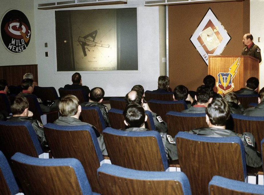 Pilots of F-4 Phantom II aircraft, 35th Tactical Fighter Wing,
listen to a briefing on flight plans during exercise Team Spirit (Coronet Spray)
Pilots of F-4 Phantom II aircraft, 35th Tactical Fighter Wing,
listen to a briefing on flight plans during exercise Team Spirit (Coronet Spray)
Heatblur deep dive videos
Episode IV - RADAR Pt. 1 - Basics and Theory
Historical documentaries and training videos
The Record-Breaking Phantom II
Other
Acronyms and Abbreviations
A
| Acronym/Abbreviation | Meaning |
|---|---|
| ACL | Automatic Carrier Landing |
| ACLS | Automatic Carrier Landing System |
| ACM | Air Combat Maneuver |
| ACQ | Acquisition |
| ADF | Automatic Direction Finder |
| ADI | Attitude Director Indicator |
| ADL | Armament Datum Line |
| AFCS | Automatic Flight Control System |
| AFTC | Augmenter Fan Temperature Control |
| AHRS | Attitude Heading Reference System |
| AICS | Air Inlet Control System |
| AOA | Angle of Attack |
| APC | Approach Power Compensator |
| ASH | Automatic Stored Heading |
| ATC | Active Transfer Command |
| ATLS | Automatic Thrust Limiting System |
| ATTK | Attack |
| AVTR | Airborne Video Tape Recorder |
| AWL | All-Weather Landing |
B
| Acronym/Abbreviation | Meaning |
|---|---|
| BATR | Bullet at Target Range |
| BDHI | Bearing-Distance-Heading Indicator |
| BIT | Built-in Test |
| BRC | Base Recovery Course |
| BRST | Boresight |
| BRU | Bomb Rack Unit |
C
| Acronym/Abbreviation | Meaning |
|---|---|
| CADC | Central Air Data Computer |
| CAINS | Carrier Aircraft Inertial Navigation System |
| CANTCO | Can’t Comply |
| CAP | Computer Address Panel |
| CCIP | Continuously Computed Impact Point |
| CICU | Computer Integrated Converter Unit |
| CLSN | Collision |
| CM | Continuous Monitor |
| CRS | Course |
| CRT | Cathode Ray Tube |
| CSA | Continuous Semi-Active |
| CSDC | Computer Signal Data Converter |
| CTVS | Cockpit Television Sensor |
| CV | Aircraft Carrier |
| CW | Continuous-Wave |
D
| Acronym/Abbreviation | Meaning |
|---|---|
| DDD | Detail Data Display |
| DDI | Digital Data Indicator |
| DECM | Defensive Electronic Countermeasures |
| DEF PT | Defended Point |
| DES | Designate |
| DEST | Destination |
| DF | Direction Finder |
| D/L | Data Link |
| DLC | Direct Lift Control |
| DME | Distance Measuring Equipment |
| DPLR | Doppler |
E
| Acronym/Abbreviation | Meaning |
|---|---|
| ECA | Expanded Chaff Adapter |
| ECM | Electronic Countermeasures |
| ECCM | Electronic Counter-Countermeasures |
| ECMD | Electronic Countermeasures Display |
| ECS | Environmental Control System |
| EGT | Exhaust Gas Temperature |
| EIG | Engine Instrument Group |
| ETA | Estimated Time of Arrival |
| EXP | Expand |
F
| Acronym/Abbreviation | Meaning |
|---|---|
| FCLP | Field Carrier Landing Practice |
| FEMS | Fatigue Engine Monitoring System |
| FF | Fuel Flow |
| FLOLS | Fresnel Lens Optical Landing System |
| FMR | Frequency Ranging |
| FOV | Field of View |
| FRL | Fuselage Reference Line |
| FSK | Frequency-Shift-Keyed |
| FWD | Forward |
G
| Acronym/Abbreviation | Meaning |
|---|---|
| GACH | Gimbal Angle Crosshair |
| GCI | Ground Controlled Intercept |
| GCS | Gun Control System |
| GM | Ground Map |
| GPS | Global Positioning System |
| GSS | Gun Scoring System |
| GT | Ground Track |
H
| Acronym/Abbreviation | Meaning |
|---|---|
| HB | Homebase |
| HCU | Hand Control Unit |
| HDG | Heading |
| HOJ | Home-on-Jam |
| HOST | Hostile |
| HPRF | High Pulse Repetition Frequency |
| HSD | Horizontal Situation Display |
| HSI | Horizontal Situation Indicator |
| HUD | Heads-up Display |
I
| Acronym/Abbreviation | Meaning |
|---|---|
| IAS | Indicated Airspeed |
| ICLS | Instrument Carrier Landing System |
| ICS | Intercommunications |
| IFF | Identification Friend or Foe |
| IFR | Instrument Flight Rules |
| IFT | In-Flight Training |
| ILS | Instrument Landing System (ICLS) |
| IMN | Indicated Mach Number |
| IMU | Intertial Measurement Unit |
| INS | Intertial Navigation System |
| IP | Initial Point |
| IR | Infrared |
| IRAT | IR Angle Tracking |
| ITER | Improved Triple Ejector Rack |
| ITS | Integrated Trim System |
J
| Acronym/Abbreviation | Meaning |
|---|---|
| JAM | Jamming |
| JAT | Jam Angle Track |
K
| Acronym/Abbreviation | Meaning |
|---|---|
| KCAS | Knots Calibrated Airspeed |
| KTS | Knots |
L
| Acronym/Abbreviation | Meaning |
|---|---|
| LAR | Launch Acceptable Region |
| LCD | Liquid Crystal Display |
| LCOS | Lead Computing Optical Sight |
| LOS | Line of Sight |
| LPRF | Low Pulse Repetition Frequency |
| LSO | Landing Signal Officer or “Paddles” |
| LTE | Launch-to-Eject |
M
| Acronym/Abbreviation | Meaning |
|---|---|
| M | Mach |
| MA | Missile Alert |
| MAD | Magnetic Azimuth Detector |
| MAG VAR | Magnetic Variation |
| MAN | Manual |
| MAND | Mandatory |
| MDIG | Multipurpose Display Indicator Group |
| MEC | Main Engine Control |
| MIL | Military |
| ML | Missile Launch |
| MLC | Mainlobe Clutter |
| MLG | Main Landing Gear |
| MOAT | Missile on Aircraft Test |
| MMGS | Multiple Mode Gun Sight |
| MRL | Manual Rapid Lockon |
| MSL | Mean Sea Level |
N
| Acronym/Abbreviation | Meaning |
|---|---|
| NAV GRID | Navigation Command and Control Grid |
| NBR | Number |
| NFO | Naval Flight Officer |
| NFOV | Narrow Field of View |
| NM | Nautical Miles |
| NOZ | Nozzle |
| NTDS | Naval Tactical Data System |
O
| Acronym/Abbreviation | Meaning |
|---|---|
| OBC | On-Board Check |
P
| Acronym/Abbreviation | Meaning |
|---|---|
| Paddles | See LSO |
| PAL | Pilot Automatic Lockon |
| PCD | Precision Course Direction |
| PD | Pulse Doppler |
| PDCP | Pilot Display Control Panel |
| PDRSL | Pulse Doppler Radar Slaved |
| PDS | Pulse Doppler Search |
| PDSTT | Pulse Doppler Single Target Track |
| PH | AIM-54 Phoenix Missile |
| PLM | Pilot Lockon Mode |
| PRF | Pulse Repetition Frequency |
| PRI | Primary |
| PRSL | Pulse Radar Slaved |
| PS | Pulse Search |
| PSTT | Pulse Single Target Track |
| PT | Point |
Q
| Acronym/Abbreviation | Meaning |
|---|---|
| QADL | Cue-to-ADL |
| QDES | Cue-to-Designate |
| QHUD | Cue-to-HUD |
| QSNO | Cue-to-snowplow |
| QWP | Cue-to-waypoint |
R
| Acronym/Abbreviation | Meaning |
|---|---|
| RACH | Radar Angle Crosshair |
| RDR | Radar |
| RDROT | Radar on Target |
| RECON | Reconnaissance |
| RIO | Radar Intercept Officer |
| RNG | Range |
| RNGRT | Range Rate |
| ROT | Range on Target |
| RTGS | Real-Time Gun Sight |
| RWS | Range While Search |
S
| Acronym/Abbreviation | Meaning |
|---|---|
| SAM | Surface to Air Missile |
| SAS | Stability Augmentation System |
| SAT | Simultaneous Alignment and Test |
| SCP | Sensor Control Panel |
| SD/A | Sample Data/Active |
| SEAM | Sidewinder Expanded Acquisition Mode |
| SINS | Ship Inertial Navigation System |
| SP | AIM-7 Sparrow Missile |
| ST | Surface Target |
| STAB | Stabilization |
| STAB AUG | Stability Augmentation |
| STBY | Standby |
| STC | Sensitivity Time Control |
| STT | Single Target Track |
| SW | AIM-9 Sidewinder Missile |
T
| Acronym/Abbreviation | Meaning |
|---|---|
| TACAN | Tactical Air Navigation |
| TARPS | Tactical Air Reconnaissance Pod System |
| TAS | True Airspeed |
| TCS | Television Camera Set |
| TDS | Tactical Data System |
| TER | Triple Ejector Rack |
| TGT | Target |
| THRLD | Threshold |
| TID | Tactical Information Display |
| TIT | Turbine Inlet Temperature |
| TTG | Time-to-Go |
| TUIR | Time Until in Range |
| TUMR | Time Until Maximum Range |
| TUOR | Time Until Optimum Range |
| TWS | Track While Scan |
| TWSA | Track While Scan Automatic |
| TWSM | Track While Scan Manual |
U
| Acronym/Abbreviation | Meaning |
|---|---|
| UHF | Ultra High Frequency |
| UTC | Coordinated Universal Time |
V
| Acronym/Abbreviation | Meaning |
|---|---|
| Vc | Closing Velocity Rate |
| vC | Computed MAG VAR |
| VDI | Vertical Display Indicator |
| VDIG | Vertical Display Indicator Group (HUD & VDI) |
| VEC | Vector |
| VFR | Visual Flight Rules |
| VID | Visual Identification |
| vM | Manual MAG VAR |
| VMCU | Voltage Monitor Control Unit |
| VSL | Vertical Scan Lockon |
| VTR | Video Tape Recorder |
W
| Acronym/Abbreviation | Meaning |
|---|---|
| WCS | Weapon Control System |
| WFOV | Wide Field of View |
| WILCO | Will Comply |
| WOD | Wind over the Deck |
| WOW | Weight on/off Wheels |
Y
| Acronym/Abbreviation | Meaning |
|---|---|
| YY | Geographic Reference Point for NAV GRID |
Imprint
Heatblur Simulations™
Ulica Wrzosowa 11, 72-602, Świnoujście, Poland
Contact: support@heatblur.se
The Heatblur F-4E Team
Nicholas Dackard, Creative Director and Lead Artist
Krzysztof Sobczak, Technical Director and Lead Programmer
Aleksander Studen-Kirchner, Lead Producer and Narrative Lead
Daniel Tischner, Senior Programmer (UI, Systems and AI)
Dominik Głowacki, Senior Programmer (Systems, Avionics, AI)
Szymon Skarzyński, Senior Programmer (Systems, Avionics, AI)
Andrew O’Donnell, Senior Programmer (Flight Dynamics and Engines)
Joshua Nelson, Senior Programmer (Weapons, Radar and Systems)
Terje Lindtveit, Programmer (Flight Dynamics and Engines)
Zander Labuschagne, Programmer (Systems and Avionics)
Will Harradine, Programmer (Systems and Avionics)
Igor Własny, Programmer (Systems and Avionics)
Yannis Leon Bößmann, Junior Programmer, Manual Editor
Nicola Faggiani, Artist, 3D Model
Davi Bernardino, Artist, 3D Model and Textures
Leon Foty, Artist, 3D Model
Ben Mährlein, Liveries and Art
Kenneth Ellis, Lead Author Manual
Andreas Sandin, Lead Design and Web-Design
Adrian Caparzo, Video Editing and Trailers
Grayson Frohberg, Voice of the JESTER-AI
Jonathan Williams, Voice of the CREW CHIEF
Gabriel Stangl, Training Missions and Lessons
Daria Kurhuzova, Administrative Assistant
See You In The Skies